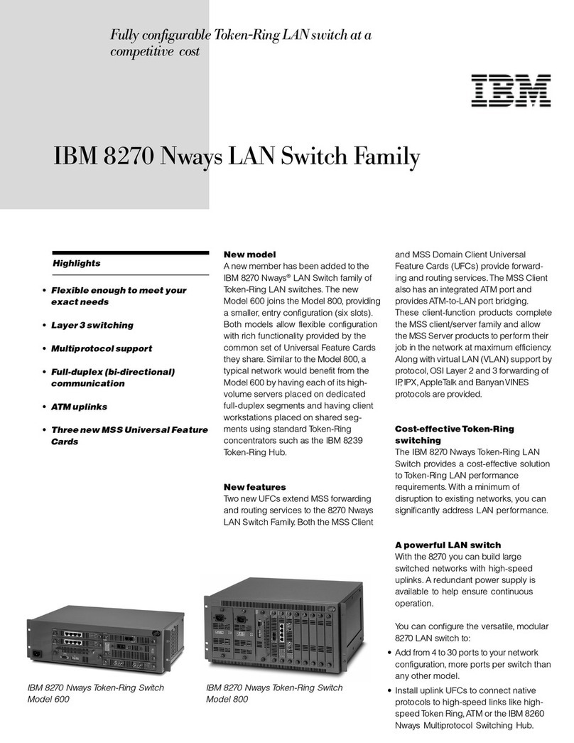
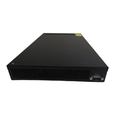
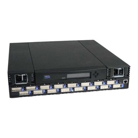
IBM 8270 Installation and maintenance instructions

8270 Models 600 and 800 ÉÂÔ
Installation and Service Guide

Note
Before using this information and the product it supports, be sure to read the general information in Appendix B,
“Notices and Product Warranty” and “Electronic Emission Notices” on page B-1.
1st Edition (July 1998)
The following paragraph does not apply to the United Kingdom or any country where such provisions are inconsistent with local
law: INTERNATIONAL BUSINESS MACHINES CORPORATION PROVIDES THIS PUBLICATION “AS IS” WITHOUT WARRANTY OF ANY KIND,
EITHER EXPRESS OR IMPLIED, INCLUDING, BUT NOT LIMITED TO, THE IMPLIED WARRANTIES OF MERCHANTABILITY OR FITNESS FOR A
PARTICULAR PURPOSE. Some states do not allow disclaimer of express or implied warranties in certain transactions, therefore, this statement may
not apply to you.
This publication could include technical inaccuracies or typographical errors. Changes are periodically made to the information herein; these changes
will be incorporated in new editions of the publication. IBM may make improvements and/or changes in the product(s) and/or program(s) described in
this publication at any time.
It is possible that this publication may contain reference to, or information about, IBM products (machines and programs), programming, or services that
are not announced in your country. Such references or information must not be construed to mean that IBM intends to announce such IBM products,
programming, or services in your country.
Requests for technical information about IBM products should be made to your IBM Authorized Dealer or your IBM Marketing Representative.
A form for readers’ comments appears at the back of this publication. If the form has been removed, address your comments to:
Department CGF
Design & Information Development
IBM Corporation
PO Box 12195
RESEARCH TRIANGLE PARK NC 27709-9990
USA
When you send information to IBM, you grant IBM a nonexclusive right to use or distribute the information in any way it believes appropriate without
incurring any obligation to you.
Copyright International Business Machines Corporation 1998. All rights reserved.
Note to U.S. Government Users — Documentation related to restricted rights — Use, duplication or disclosure is subject to
restrictions set forth in GSA ADP Schedule Contract with IBM Corp.

Contents
Safety Information . . . . . . . . . . . . . . . . . . . . . . . . . . . . . . . . . . vii
About This Manual .................................. xv
How This Manual Is Organized ............................ xv
Prerequisite Publication . . . . . . . . . . . . . . . . . . . . . . . . . . . . . . . . xv
Related Publications . . . . . . . . . . . . . . . . . . . . . . . . . . . . . . . . . . xv
Chapter 1. Physical Characteristics and Features ............... 1-1
Physical Characteristics . . . . . . . . . . . . . . . . . . . . . . . . . . . . . . . . 1-2
Power Supply . . . . . . . . . . . . . . . . . . . . . . . . . . . . . . . . . . . . 1-3
Processor Card . . . . . . . . . . . . . . . . . . . . . . . . . . . . . . . . . . . 1-5
Universal Feature Cards .............................. 1-8
Dimensions and Weight ............................. 1-10
Power Requirements . . . . . . . . . . . . . . . . . . . . . . . . . . . . . . . 1-10
Operating Environment . . . . . . . . . . . . . . . . . . . . . . . . . . . . . . 1-10
Functional Overview . . . . . . . . . . . . . . . . . . . . . . . . . . . . . . . . . 1-11
Switch Configuration for Optimum Performance ............... 1-11
Chapter 2. Installation . . . . . . . . . . . . . . . . . . . . . . . . . . . . . . . . 2-1
Installation Summary . . . . . . . . . . . . . . . . . . . . . . . . . . . . . . . . . . 2-1
Unpacking the Token-Ring Processor Card (8270-800 Only) .......... 2-1
Unpacking the 8270 Chassis ............................. 2-2
Other Materials You Will Need ............................ 2-2
Installing the Token-Ring Processor Card (8270-800 Only) ........... 2-3
Surface Mounting . . . . . . . . . . . . . . . . . . . . . . . . . . . . . . . . . . . . 2-5
Rack-Mounting the 8270-600 ............................. 2-6
Rack-Mounting the 8270-800 ............................. 2-7
Installing a Universal Feature Card ........................ 2-15
Installing the Second Power Supply (8270-800 Only) .............. 2-19
Cabling . . . . . . . . . . . . . . . . . . . . . . . . . . . . . . . . . . . . . . . . . 2-21
Connecting Devices to the Token-Ring Ports ................. 2-21
Connecting Devices to the Token-Ring Ports Using Building Wiring .... 2-23
Powering On the 8270 ................................ 2-24
Powering on the 8270-600 ............................ 2-24
Powering on the 8270-800 ............................ 2-25
Power-On Checkout . . . . . . . . . . . . . . . . . . . . . . . . . . . . . . . 2-26
Chapter 3. Setting up a Console Session .................... 3-1
Chapter 4. Updating Software . . . . . . . . . . . . . . . . . . . . . . . . . . . 4-1
Download the Diskette Image from the Internet .................. 4-1
Download the Code into the 8270 .......................... 4-1
Initiating a Download with the System Request Menu ............. 4-2
Serial Port or TFTP Downloading with the Download Menu .......... 4-3
BootP . . . . . . . . . . . . . . . . . . . . . . . . . . . . . . . . . . . . . . . . . 4-5
Chapter 5. Troubleshooting and Service .................... 5-1
Obtaining Software . . . . . . . . . . . . . . . . . . . . . . . . . . . . . . . . . . . 5-1
Troubleshooting in a Network ............................. 5-1
Start of Troubleshooting Process ........................... 5-1
Copyright IBM Corp. 1998 iii
Choosing a Troubleshooting Procedure ....................... 5-2
Procedure A . . . . . . . . . . . . . . . . . . . . . . . . . . . . . . . . . . . . . 5-3
Procedure B . . . . . . . . . . . . . . . . . . . . . . . . . . . . . . . . . . . . . 5-3
Procedure C . . . . . . . . . . . . . . . . . . . . . . . . . . . . . . . . . . . . . 5-4
Procedure D . . . . . . . . . . . . . . . . . . . . . . . . . . . . . . . . . . . . . 5-4
Obtaining Service . . . . . . . . . . . . . . . . . . . . . . . . . . . . . . . . . . . . 5-6
Chapter 6. Service Procedures for Qualified Personnel ........... 6-1
Parts Listing . . . . . . . . . . . . . . . . . . . . . . . . . . . . . . . . . . . . . . . 6-1
Assembly 1: 8270-600 . . . . . . . . . . . . . . . . . . . . . . . . . . . . . . . 6-1
Assembly 2: Front View 8270-800 ........................ 6-2
Assembly 3: Rear View 8270-800 ........................ 6-3
Assembly 4: Line Cords . . . . . . . . . . . . . . . . . . . . . . . . . . . . . . 6-4
Replacing a Fan in an 8270-600 ........................... 6-5
Replacing a Power Supply in an 8270-600 ..................... 6-5
Replacing a Fan in an 8270-800 ........................... 6-5
Replacing a Fuse in an 8270-800 .......................... 6-6
Appendix A. Cable and Pin Information .................... A-1
Connecting to the Management (EIA 232) Port ................. A-1
Twisted-Pair Cable Pinouts ............................. A-1
Straight-Through 100-Ohm and 120-Ohm Cable ............... A-1
150-Ohm Data Connector-to-RJ-45 Straight-Through Cable ........ A-2
EIA 232 Port and Cable Pinouts .......................... A-2
EIA 232 Port Pinout ................................ A-2
EIA 232 Modem Cable Connections ...................... A-3
EIA 232 Null-Modem Connections ....................... A-3
Cabling Recommendations . . . . . . . . . . . . . . . . . . . . . . . . . . . . . A-4
Length Recommendations for Dedicated-Media LAN Segments ...... A-5
Lobe Wiring Rules for Dedicated-Media LAN Segments ........... A-5
Cable Length and Lobe Wiring Rules for Shared-Media LAN Segments . A-6
Number of Attaching Devices .......................... A-6
Appendix B. Notices and Product Warranty ................. B-1
Electronic Emission Notices ........................... B-1
Statement of Compliance with the United Kingdom Telecommunications Act
1984 . . . . . . . . . . . . . . . . . . . . . . . . . . . . . . . . . . . . . . . . . B-2
Power Line Harmonics Compliance Statement ................ B-3
Lithium Battery Notice .............................. B-3
Trademarks . . . . . . . . . . . . . . . . . . . . . . . . . . . . . . . . . . . . . . B-4
Warranty . . . . . . . . . . . . . . . . . . . . . . . . . . . . . . . . . . . . . . . . B-5
Index . . . . . . . . . . . . . . . . . . . . . . . . . . . . . . . . . . . . . . . . . . X-1
iv 8270 Nways LAN Switch Models 600 and 800

Figures
1-1. The IBM 8270 Nways Token-Ring LAN Switch Model 800 and 600 . 1-1
1-2. The 8270-600 Front View .......................... 1-2
1-3. The 8270-800 Front View .......................... 1-3
1-4. The 8270-800 Power Supply ........................ 1-4
1-5. The 8270-800 Power Supply Faceplate .................. 1-5
1-6. The Token-Ring Processor Card Faceplate ............... 1-6
2-1. The 8270-800 As It Is Shipped. ...................... 2-3
2-2. Installing the Token-Ring Processor Card ................ 2-4
2-3. Securing the Token-Ring Processor Card ................ 2-5
2-4. Installing the 8270-600 in the Rack .................... 2-7
2-5. Removing the Power Supply from the 8270-800 ............ 2-8
2-6. Installing the 8270-800 Cable Management Bracket ......... 2-10
2-7. Installing the 8270-800 in the Rack ................... 2-11
2-8. Installing the Power Supply in the 8270-800 .............. 2-13
2-9. Removing a UFC Slot Cover ....................... 2-16
2-10. Installing a UFC .............................. 2-17
2-11. Inserting the Second Power Supply ................... 2-19
2-12. Securing the Second Power Supply ................... 2-20
2-13. Connecting Devices to Token-Ring Ports ................ 2-22
2-14. Connecting Devices to Token-Ring Ports Using Building Wiring .. 2-23
2-15. Powering On the 8270 .......................... 2-24
2-16. Powering On the 8270-800 ........................ 2-25
4-1. System Request Menu ........................... 4-2
4-2. Download Menu . . . . . . . . . . . . . . . . . . . . . . . . . . . . . . . 4-3
4-3. TFTP Download Panel ........................... 4-5
4-4. Example of a BOOTPTAB File ....................... 4-7
6-1. 8270-800 Fuse and Fan Connector Panel ................ 6-6
A-1. Straight-Through Cable . . . . . . . . . . . . . . . . . . . . . . . . . . A-2
A-2. 150-Ohm Data Connector-to-RJ-45 Straight-Through Cable ..... A-2
A-3. Pinout of the EIA 232 Port ........................ A-3
A-4. EIA 232 Modem Cable for Terminal with 25-Pin Connector ..... A-3
A-5. EIA 232 Null-Modem Cable for Terminal with 25-Pin Connector .. A-3
A-6. EIA 232 Null-Modem Cable for Terminal with 9-Pin Connector ... A-4
Copyright IBM Corp. 1998 v

Tables
1-1. Power Supply Status LEDs (8270-800 Only) ............... 1-5
1-2. Status LEDs . . . . . . . . . . . . . . . . . . . . . . . . . . . . . . . . . 1-7
1-3. Token-Ring Port LEDs .......................... 1-10
1-4. Dimensions and Weight .......................... 1-10
1-5. Operating Environment . . . . . . . . . . . . . . . . . . . . . . . . . . 1-10
2-1. 8270-800 Installation Procedures ..................... 2-1
2-2. Normal State of Status LEDs ....................... 2-26
5-1. Symptom, LED State, and Recommended Procedure ......... 5-3
6-1. Fuse Power Control ............................. 6-7
A-1. Connecting to the EIA 232 Port ..................... A-1
A-2. Copper Cable Types ........................... A-4
A-3. Multimode Optical Fiber Cable Types .................. A-4
A-4. Lobe Lengths for 150-Ohm, Shielded Media .............. A-5
A-5. Lobe Lengths for 100-/120-Ohm, Shielded or Unshielded Cable .. A-5
A-6. Lobe Lengths for 100-/120-Ohm, Shielded or Unshielded Cable .. A-5
vi 8270 Nways LAN Switch Models 600 and 800

Safety Information
Danger: Before you begin to install this product, read the safety information
in
Caution: Safety Information—Read This First
, SD21-0030. This booklet
describes safe procedures for cabling and plugging in electrical equipment.
Danger: No user serviceable parts inside product. Refer service to qualified
personnel.
Varning — livsfara: Innan du börjar installera den här produkten bör du
läsa säkerhetsinformationen i dokumentet
Varning: Säkerhetsföreskrifter— Läs
detta först,
SD21-0030. Där beskrivs hur du på ett säkert sätt ansluter elektrisk
utrustning.
VARNING: Service ska endast utföras av utbildad servicepersonal.
Fare: Før du begynner å installere dette produktet, må du lese
sikkerhetsinformasjonen i
Advarsel: Sikkerhetsinformasjon — Les dette først
,
SD21-0030 som beskriver sikkerhetsrutinene for kabling og tilkobling av elektrisk
utstyr.
Fare: Inneholder ingen deler som kan repareres av brukeren. Overlat
service til kvalifisert personell.
Fare! Før du installerer dette produkt, skal du læse sikkerhedsforskrifterne i
NB: Sikkerhedsforskrifter—Læs dette først
SD21-0030. Vejledningen beskriver
den fremgangsmåde, du skal bruge ved tilslutning af kabler og udstyr.
Fare! Indvendigt eftersyn af dette produkt må kun foretages af
servicepersonale.
Gevaar: Voordat u begint met de installatie van dit produkt, moet u eerst de
veiligheidsinstructies lezen in de brochure
PAS OP! Veiligheidsinstructies—Lees dit
eerst,
SD21-0030. Hierin wordt beschreven hoe u electrische apparatuur op een
veilige manier moet bekabelen en aansluiten.
GEVAAR: Dit produkt bevat geen onderdelen die door de gebruiker kunnen
worden hersteld. Voor herstellingen moet u een beroep doen op gespecialiseerd
onderhoudspersoneel.
Copyright IBM Corp. 1998 vii

Gevaar: Voordat u begint met het installeren van dit produkt, dient u eerst
de veiligheidsrichtlijnen te lezen die zijn vermeld in de publikatie
Caution: Safety
Information - Read This First
, SD21-0030. In dit boekje vindt u veilige procedures
voor het aansluiten van elektrische appratuur.
GEVAAR: In dit product bevinden zich geen onderdelen die door de
gebruiker kunnen worden onderhouden. Laat onderhoud over aan bevoegd
personeel.
Vorsicht: Bevor mit der Installation des Produktes begonnen wird, die
Sicherheitshinweise in
Achtung: Sicherheitsinformationen—Bitte zuerst lesen,
IBM
Form SD21-0030. Diese Veröffentlichung beschreibt die Sicherheitsvorkehrungen
für das Verkabeln und Anschließen elektrischer Geräte.
Vorsicht: Keine vom Benutzer zu wartenden Teile vorhanden.
Instandhaltungsarbeiten dürfen nur von Fachpersonal durchgeführt werden.
Danger : Avant d'installer le présent produit, consultez le livret
Attention :
Informations pour la sécurité — Lisez-moi d'abord
, SD21-0030, qui décrit les
procédures à respecter pour effectuer les opérations de câblage et brancher les
équipements électriques en toute sécurité.
Danger: Le produit ne contient pas de pièces réparables par l'utilisateur.
Adressez-vous à du personnel qualifié pour les réparations.
Danger: Avant de procéder à l'installation de ce produit, lisez d'abord les
consignes de sécurité dans la brochure
ATTENTION: Consignes de sécurité—A
lire au préalable,
SD21-0030. Cette brochure décrit les procédures pour câbler et
connecter les appareils électriques en toute sécurité.
viii 8270 Nways LAN Switch Models 600 and 800

Danger: Ce produit ne contient pas d'éléments susceptibles d'être
entretenus par l'utilisateur. Faites appel à un technicien qualifié.
Pericolo: prima di iniziare l'installazione di questo prodotto, leggere le
informazioni relative alla sicurezza riportate nell'opuscolo
Attenzione: Informazioni
di sicurezza — Prime informazioni da leggere
in cui sono descritte le procedure per
il cablaggio ed il collegamento di apparecchiature elettriche.
Pericolo: Questo prodotto non contiene parti sostituibili dall'utente. Se
occorre, richiedere assistenza tecnica a personale specializzato.
Perigo: Antes de iniciar a instalação deste produto, leia as informações de
segurança
Cuidado: Informações de Segurança — Leia Primeiro
, SD21-0030.
Este documento descreve como efectuar, de um modo seguro, as ligações
eléctricas dos equipamentos.
Perigo: Nenhum dos componentes internos pode ser reparado pelo cliente.
Para qualquer reparação, chame sempre um técnico especializado.
Peligro: Antes de empezar a instalar este producto, lea la información de
seguridad en
Atención: Información de Seguridad — Lea Esto Primero,
SD21-0030.
Este documento describe los procedimientos de seguridad para cablear y enchufar
equipos eléctricos.
Peligro: Dentro del producto no hay piezas a las que el usuario pueda
prestar servicio técnico. Ceda el servicio a personal cualificado.
Perigo: Antes de começar a instalar este produto, leia as informações de
segurança contidas em
Cuidado: Informações Sobre Segurança—Leia Isto
Primeiro,
SD21-0030. Esse folheto descreve procedimentos de segurança para a
instalação de cabos e conexões em equipamentos elétricos.
Perigo: Dentro deste produto não existem peças que possam ser
manuseadas por parte do usuário. Qualquer serviço dentro deste produto deverá
ser executado por pessoa autorizada e qualificada.
VAARA: Ennen kuin aloitat tämän tuotteen asennuksen, lue julkaisussa
Varoitus: Turvaohjeet—Lue tämä ensin
, SD21-0030, olevat turvaohjeet. Tässä
kirjasessa on ohjeet siitä, miten sähkölaitteet kaapeloidaan ja kytketään turvallisesti.
VAARA: Tuotteessa ei ole käyttäjän huollettavaksi tarkoitettuja osia.
Tuotteen saa huoltaa vain ammattitaitoinen huoltoedustaja.
Safety Information ix

x8270 Nways LAN Switch Models 600 and 800

Vigyázat: Mielôtt megkezdi a berendezés üzembe helyezését, olvassa el a
Caution: Safety Information— Read This First,
SD21-0030 könyvecskében leírt
biztonsági információkat. Ez a könyv leírja, milyen biztonsági intézkedéseket kell
megtenni az elektromos berendezés huzalozásakor illetve csatlakoztatásakor.
OPOZORILO: Proizvod ne vsebuje delov, katere sme servisirati uporabnik.
Servis zaupajte kvalificiranemu osebju.
Safety Information xi

Opasnost: Ne sadrzi dijelove popravljive od strane korisnika.
Odrzavanje prepustiti ovlastenom osoblju.
xii 8270 Nways LAN Switch Models 600 and 800

Safety Information xiii

xiv 8270 Nways LAN Switch Models 600 and 800

About This Manual
This manual explains how to install and service the IBM 8270 Nways Token-Ring
LAN Switch Models 600 and 800 (hereafter referred to as
8270-600
and
8270-800
).
8270 refers to both 8270-600 and 8270-800.
The 8270 comes preconfigured for Plug and Play capability. You might not have to
configure the switch for it to operate in your network. However, should you choose
to change default settings, refer to
Planning, Configuration, and Operation
, which is
on the 8270 Switch User's Guide CD-ROM.
How This Manual Is Organized
¹Chapter 1, “Physical Characteristics and Features” describes the 8270. It also
provides a brief functional overview.
¹Chapter 2, “Installation” describes installation and cabling procedures.
¹Chapter 3, “Setting up a Console Session” describes how to set up a local or
remote console.
¹Chapter 4, “Updating Software” describes procedures for downloading new
code.
¹Chapter 5, “Troubleshooting and Service” provides troubleshooting procedures
and how to get help from IBM.
¹Chapter 6, “Service Procedures for Qualified Personnel” describes the parts
that can be replaced by qualified service personnel and step-by-step
procedures for replacing these parts.
¹Appendix A, “Cable and Pin Information” provides detailed information about
cables that can be used with the 8270.
¹Appendix B, “Notices and Product Warranty” describes product notices and
provides warranty information.
Prerequisite Publication
Caution: Safety Information—Read This First
, SD21-0030.
Related Publications
¹
Token-Ring Network, Introduction and Planning Guide
, GA27-3677
¹
IBM 8270 Publication CD-ROM
— SK2T-0434-00.
Copyright IBM Corp. 1998 xv

xvi 8270 Nways LAN Switch Models 600 and 800

Chapter 1. Physical Characteristics and Features
The IBM 8270 Nways Token-Ring LAN Switch is a member of and fully compatible
with the 8270 family of LAN switches, which includes the 8272 Nways Token-Ring
LAN Switch, Models 108 and 216, and the 8272 LAN Switch Modules, Feature
Codes 5208, 5308, 6208 and 6308, for the IBM 8260 Nways Multiprotocol
Switching Hub and 8265 Nways ATM Switch.
The 8270 provides high-speed forwarding of Token-Ring frames among the shared
or dedicated Token-Ring segments attached to each of the 8270 ports. The 8270
creates multiple, concurrent paths among the connected segments, each supporting
the full, 16-Mbps Token-Ring bandwidth. The 8270 also supports ATM uplink
connections.
The 8270 forwards Token-Ring frames among multiple, shared or dedicated,
Token-Ring LAN segments. Using a frame-forwarding technique similar to that of a
multiport, Token-Ring transparent bridge, the 8270 uses both Token-Ring MAC
addresses and source-route descriptors to forward Token-Ring frames from one of
its ports to another.
Figure 1-1. The IBM 8270 Nways Token-Ring LAN Switch Model 800 and 600
The 8270 is a rack- or surface-mount chassis that provides slots for one
Token-Ring Processor Card and up to six (for the 8270-600) or eight (for the
Copyright IBM Corp. 1998 1-1

8270-800) Universal Feature Cards (UFCs). In addition to supporting more UFCs,
the 8270-800 can have redundant, load-sharing power supplies and redundant
cooling fans. The 8270 can connect to Token-Ring and ATM networks. All LAN
ports on the 8270 are provided by UFCs. At least one UFC must be installed in
order to have a functional unit. The following UFCs can be installed in the 8270:
¹4-Port Token-Ring/Enhanced UTP/STP UFC
¹2-Port Token-Ring/Enhanced Fiber UFC
¹ATM 155-Mbps Multimode Fiber/Token-Ring II UFC
¹MSS Client Single Mode Fiber UFC
¹MSS Client Multimode Fiber UFC
¹MSS Domain Client UFC
Physical Characteristics
The 8270 consists of a base unit, a Token-Ring Processor Card, and at least one
Universal Feature Card (UFC). The 8270-800 can have either one or two power
supplies.
The front views of the 8270-600 and 8270-800 are illustrated in Figure 1-2 and
Figure 1-3 on page 1-3 respectively. Following the illustrations is a description of
each of the plug-in modules and UFCs. The connectors, indicators, and switches
for each module are also discussed.
Figure 1-2. The 8270-600 Front View
1-2 8270 Nways LAN Switch Models 600 and 800

100 - 240V
6 - 3A 50/60Hz
P/N 72H4648
100 - 240V
6 - 3A 50/60Hz
P/N 72H4648
DC OK DC OK
AC OK AC OK
Token-Ring
Processor Card
P/N XXHXXXX
FRU XXHXXXX
OK
(EIA 232)
Management
Status
Reset
OKConnect
FDX
Tx/Rx
12341234
Tok enR
ing
P/N85H5092
OKConnect
FDX
Tx/Rx
12341234
Tok enR
ing
P/N85H5092
OKConnect
FDX
Tx/Rx
12341234
Tok enR
ing
P/N 85H5092
OKConnect
FDX
Tx/Rx
12341234
Tok enR
ing
P/N85H5092
OKConnect
FDX
Tx/Rx
12341234
Tok enR
ing
P/N85H5092
OKConnect
FDX
Tx/Rx
12341234
Tok enR
ing
P/N85H5092
OKConnect
FDX
Tx/Rx
12341234
Tok enR
ing
P/N85H5092
OKConnect
FDX
Tx/Rx
12341234
Tok enR
ing
P/N85H5092
Token-Ring
Processor Card
UFC Slot 1 UFC Slot 8
Serial
Number
Label
Power
Supplies
Figure 1-3. The 8270-800 Front View
Power Supply The 8270-600 has a single internal power supply, while the 8270-800 provides the
capability to have two power supplies. Both the 8270-600 and the 8270-800 can
operate on input line voltage from 100—240 volts.
8270-800 Power Supply:
The 8270-800 provides two slots for power supplies.
These are the two leftmost slots in the chassis. (see Figure 1-3). At least one
power supply must be installed. The 8270-800 is shipped with a single power
supply installed in the right slot. The left slot is available for installation of an
optional, redundant power supply.
If two power supplies are installed, they share the power load. In the event of a
failure by either supply, the good power supply automatically maintains power for
the entire 8270-800. Operation of the 8270-800 is not disrupted.
The 8270-800 power supplies are
hot-pluggable
That means they can be removed
and installed while the 8270-800 is powered up. When two power supplies are
installed, hot-plugging allows a failed power supply to be replaced without
disrupting operation of the switch. Both power supplies must have a line cord
connected to ac power.
Figure 1-4 on page 1-4 illustrates the 8270-800 power supply.
Chapter 1. Physical Characteristics and Features 1-3

100 - 240V
6 - 3A 50/60Hz
P/N 72H4648
DC OK
AC OK
Fan
Figure 1-4. The 8270-800 Power Supply
The integrated cooling fan for the power supply is located at the rear of the module.
Details of the power supply faceplate are shown in Figure 1-5 on page 1-5.
1-4 8270 Nways LAN Switch Models 600 and 800
This manual suits for next models
2
Other IBM Switch manuals

IBM
IBM RedBooks SAN24B-5 User manual

IBM
IBM 6 MPLS User manual

IBM
IBM 8275-416 User manual

IBM
IBM 8270 600 User manual

IBM
IBM 17353LX - 1x8 Console Switch User manual

IBM
IBM 3454-A3C User manual

IBM
IBM Brocade FCoE User manual

IBM
IBM Flex System FC3171 User manual

IBM
IBM 8271 Nways Ethernet LAN Switch User manual

IBM
IBM 2109 - SAN Fibre Channel Switch Model S16 User manual
Popular Switch manuals by other brands

AXIOMTEK
AXIOMTEK TEN710 Series user manual

THOMSON
THOMSON Grass Valley TRITON TTN-BTS-6464/34 installation manual

TFortis
TFortis SWD-1 Operation manual

Safe Living Technologies
Safe Living Technologies NEFA 20-plus F/1 installation guide

H3C
H3C NSQ1GP24TXEA0 LPU manual

Radial Engineering
Radial Engineering Relay Xo user guide