ICI APEX 200 User manual

APEX 200
User Manual V1.0.6
ICI Infrared Cameras Inc.

APEX 200 User Manual
I
Table of Contents
1.Safety Information..................................................................................................................................................1
3.Product Figure and Explanation........................................................................................................................ 3
4.Quick Start Guide................................................................................................................................................... 4
5.Product and Accessories List.............................................................................................................................5
6.Mechanical Installation......................................................................................................................................... 6
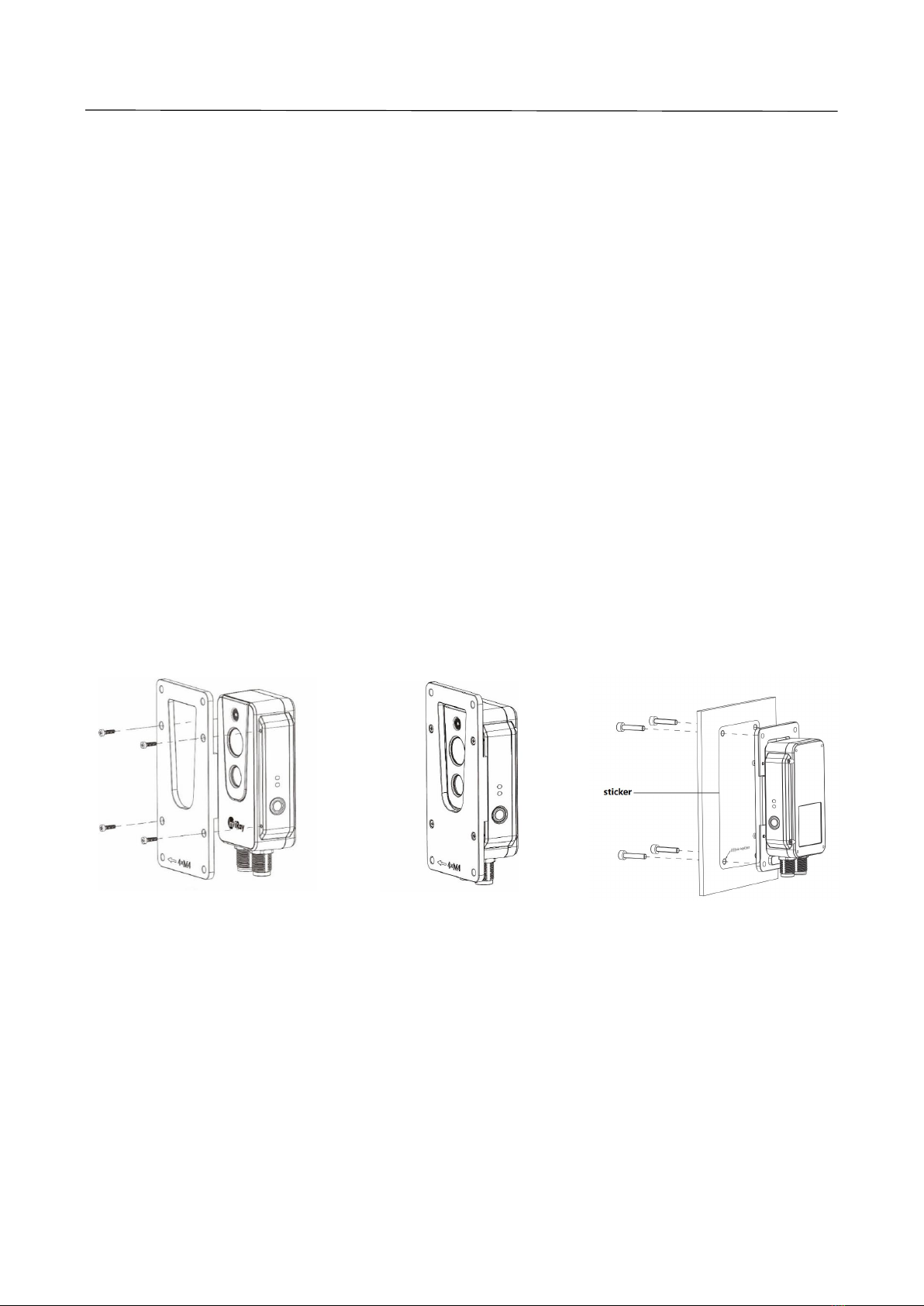
6.1 Installing Housings with Screws................................................................................................................. 7
6.1.1 Installing Front Housing.................................................................................................................... 7
6.1.2 Installing Rear Housing.....................................................................................................................7
6.2 Front Mounting...............................................................................................................................................8
6.3 Rear Mounting............................................................................................................................................... 9
7.Alarm Input and Output......................................................................................................................................10
7.1 Alarm Input................................................................................................................................................... 10
7.2 Alarm Output................................................................................................................................................10
8.Protocol Introduction.......................................................................................................................................... 11
8.1 Modbus TCP................................................................................................................................................ 11
8.2 MQTT............................................................................................................................................................ 11
9.Protocol Introduction.......................................................................................................................................... 19
9.1 Modbus TCP................................................................................................................................................ 19
10.Technical Data.....................................................................................................................................................20
11.Pin Configuration for Interfaces.................................................................................................................... 25
11.1 Ethernet Pin Configuration (8pin)...........................................................................................................25
11.2 Power Pin Configuration (12pin)............................................................................................................ 26
12.Mechanical Drawings........................................................................................................................................27
13.Common Troubleshooting...............................................................................................................................28
14.Cleaning Thermal Camera............................................................................................................................... 29
14.1 Cleaning Camera Housing, Cables and Other Items......................................................................... 29
14.2 Cleaning Infrared Lens.............................................................................................................................30
Appendix A Emissivity of Common Materials................................................................................................. 31

APEX 200 User Manual
1
1.Safety Information
WARNING
1.Before using the cleanser, make sure you read all applicable material safety data
sheets (MSDS) and warning labels on cleanser containers.
2.Do not use too long screws when installing the front/rear mounting bracket, which
may damage the thermal camera.
3.It is prohibited to place the product in a high temperature above 70°C or in a low
temperature below-45 °C.
4.It is forbidden to disassemble or refit the infrared thermal camera at will.
CAUTION
1.No matter there is a lens cover or not, do not point the infrared thermal camera
towards strong light or equipment with laser radiation. This will affect the accuracy of
the thermal camera and even damage the detector in the thermal camera.
2.Do not use the product under conditions that doesn’t match the environmental
requirements. For specific use environment requirements, see the product parameter
table.
3.Do not apply solvents or equivalent liquids to the camera, the cables, or other
items.
4.Be careful when you clean the infrared lenses. The lens has an anti-reflective
coating which is easily damaged. Damage to the infrared lens can occur with too
much force or cleaning with rough objects such as tissues.

APEX 200 User Manual
2
2.Product Introduction
Main Features
Accurate temperature measurement
Support multi-protocol access to industrial or IoT systems
Compact size
Support PoE
Bi-spectrum display
Powerful web client
Wi-Fi hotspot
Typical Applications
Monitoring power distribution cabinet
Monitoring warehouse
Monitoring production line

APEX 200 User Manual
3
3.Product Figure and Explanation
No.
Explanation
1
Fill light
2
Digital camera
3
Infrared lens
4
Ethernet and PoE cable interface
5
DC power supply and alarm input/output
6
Power LED light
7
Network LED light
8
Reset button
Table 3.1 Explanation of Product Appearance

APEX 200 User Manual
4
4.Quick Start Guide
Please follow the steps:
1. After installing the thermal camera in the desired position, use the cable to connect
the thermal camera and the computer normally. There are two power supply
methods for APEX 200. Connect the device to the PoE port of the power supply
through the M12 8-pin adapter cable or connect to the DC power supply through
the M12 12-pin adapter cable. Connect APEX 200 to the network, and wait for 2
minutes after powering on. The power indicator light is steady blue and the network
indicator light flashes green, indicating that the network connection is normal.
2. Modify the computer network segment to be the same with that of thermal camera.
The specific path is "Control Panel"-"Network and Internet"-"Network and Sharing
Center"-"Change Adapter Options"-"Ethernet"-" Properties"-"Internet Protocol
Version 4 (TCP/IPv4)" - "Use the following IP address"-set the IP address to
192.168.1.xxx.
3. After the power is on for 30 minutes, the temperature measurement, monitoring
and analysis can be carried out through the web terminal of the computer. For web
instructions, please refer to APEX 200 Online Dual-spectrum Thermal Camera
Web Client Operation Manual.

APEX 200 User Manual
5
5.Product and Accessories List
Product and Accessories
APEX 200
44cm long M12 8-pin adapter cable
Fixing accessories (screws, mounting stickers)
Table 5.1 Product and Accessories List
Optional Accessories
M12 12-pin adapter cable &alarm input/output cable
front/rear mounting bracket

APEX 200 User Manual
6
6.Mechanical Installation
The front and back of the thermal camera are equipped with mounting interfaces, which can be installed
with screws after the holes are punched with the auxiliary stickers in the package. In addition, we also
provide two optional forms of front and back installation.
WARNING
Do not use too long screws in case of damaging the thermal camera.
The maximum hole depth of the front shell is 10mm, and the maximum hole depth of
the rear shell is 4mm.
It’s normal that the thermal camera will generate heat during operation. In order to sufficiently dissipate
the heat, it is suggested that the back shell of the thermal camera should be fixed on a metal object to
minimize the temperature drift of the infrared detector in thermal camera.

APEX 200 User Manual
7
6.1 Installing Housings with Screws
6.1.1 Installing Front Housing
As shown in Figure 6.1, please paste the alignment guide to the position to be installed, and then drill 4
Φ2.5 mounting holes according to the markers on the alignment guide, and use 4 ST2.2 screws to install
the front housing.
Figure 6.1 Front Housing Installation
6.1.2 Installing Rear Housing
As shown in Figure 6.2, please paste the alignment guide to the position to be installed, and then drill 4
Φ2.5 mounting holes according to the markers on the alignment guide, and use 4 M2 screws to install the
rear housing.
Figure 6.2 Rear Housing Installation

APEX 200 User Manual
8
6.2 Front Mounting
There are four M4 threaded holes on the front mounting bracket for fixing.
Step 1 Install the front mounting bracket
As shown in Figure 6.3, connect the front mounting bracket and the thermal camera with ST2.2*8
self-tapping screws. The installation effect is shown in Figure 6.4.
Step 2 Drill holes
As shown in Figure 6.5, please paste the alignment guide to the position to be installed, and then drill four
Φ4.5 mounting holes according to the markers on the alignment guide.
Step 3 Install the thermal camera
As shown in Figure 6.5, use M4 screws to install the thermal camera to the designated location.
Figure 6.3 Figure 6.4 Figure 6.5

APEX 200 User Manual
9
6.3 Rear Mounting
There are four M4 threaded holes on the rear mounting bracket for fixing.
Step 1 Install the rear mounting bracket
As shown in Figure 6.6, connect the rear mounting bracket and the thermal camera with ST2.2*8
self-tapping screws. The effect installation is shown in Figure 6.7.
Step 2 Drill holes
As shown in Figure 6.8, please paste the alignment guide to the position to be installed, and then drill four
Φ4.5 mounting holes according to the markers on the alignment guide.
Step 3 Install the thermal camera
As shown in Figure 6.8, use M4 screws to install the thermal camera to the designated location.
Figure 6.6 Figure 6.7 Figure 6.8

APEX 200 User Manual
10
7.Alarm Input and Output
7.1 Alarm Input
Support 1 active alarm input (photoelectric isolation), and the input voltage range is 3~5.5V.
7.2 Alarm Output
Support 2 alarm outputs (switch value and photoelectric isolation), 3~25VDC, maximum 85mA.

APEX 200 User Manual
11
8.Protocol Introduction
8.1 Modbus TCP
This camera supports Modbus TCP protocol for transmitting temperature measurement information.
M12 8-pin to RJ45 cable is required when using this protocol.
IP
Camera IP(default: 192.168.1.20)
Port
1502
Register
Address
R/W
Length(word)
Data
0x0001
R
2
Version No.,e.g.0x0102 0x0304 = V1.2.3.4
0x0003
R
1
0x0004
R
1
0x0005
R
1
0x0006
R
1
0x0007
R
2
the highest temperature of the entire frame,
the actual temperature = (register value-2732) / 10.0
0x0009
R
2
the average temperature of the entire frame
0x000B
R
2
the lowest temperature of the entire frame
0x000D+N*4
R
1
Region attributes,
Bit0: region validness
Bit1~2: region type, box=0,line=1,point=2
Bit3: whether temperature alarm is on
Bit4:whether to trigger an alarm
0x000E+N*4
R
1
the highest temperature in the region
0x000F+N*4
R
1
the average temperature in the region
0x0010+N*4
R
1
the lowest temperature in the region
*N:0~15
8.2 MQTT
APEX 200 supports the MQTT protocol, as defined below:
1. The server sends the subject.
APEX 200_ICI
2. Set the configuration MQTT parameters through the Web interface, and enable the MQTT function. The
configuration will be valid after saving and restarting. The camera will automatically connect to the MQTT

APEX 200 User Manual
12
server after restarting.
3. Data format is as follows:
Image data:
{
"timestamp": "2021.4.9.15:52", #time stamp
"ip": "192.168.1.21", #camera IP
"type": 0, #data type:0-image 1-temperature 2-temperature measurement
"resolution": "1280*720", #visible light resolution
"resolution": "1024*768", #thermal resolution
"formate": ".jpg", #image format
"image": "......" # visible light image data base64 encode
"ir_image": "......" # thermal image data base64 encode
}
Temperature data:
{
"timestamp": "2021.4.9.15:52", # time stamp
"ip": "192.168.1.21", #camera IP

APEX 200 User Manual
13
"type": 1, # data type:0-image 1-temperature 2-temperature measurement
"unit": "C", #Unit:℃
"data": "......" # temperature data base64 encode
}
Temperature measurement data: temperature measurement function needs to be enabled in Web
interface.
{
"timestamp": "2021.4.9.15:52", # time stamp
"ip": "192.168.1.21", # camera IP
"type": 2, # data type:0-image 1-temperature 2-temperature measurement
"subnetmask": "255.255.255.0", #subnet mask
"gateway": "192.168.1.1", #gateway
"mac": "86:5D:55:0B:A9:74", #MAC address
"uptime":33, #boot time
"version": "V0.2.7", #software version
"airTemp": 25, #air temperature(℃)
"airtransmissivit": 1, #air transmittance
"distance": 3, #distance(m)
"emissivity": 0.95, # emissivity
"reflectemp": 25, # reflection temperature(℃)
"maxtemp": 45.6, #maximum temperature of frame(℃)
"mintemp": 44.9, # minimum temperature of frame(℃)
"avgtemp": 45.3, #average temperature of frame(℃)
"list": [{ # 16 data in the temperature measurement area, enable=1 is valid
"index": 0, # temperature index
"enable":1, #enable temperature measuring or not
"type": 0, #type: 0- rectangle 1-line 2-point
"x0": 67, #start: x value
"y0": 61, #start: y value
"x1": 125, #end: x value
"y1": 98, #end: y value
"maxTemp": 45.5, # maximum temperature of the region(℃)
"minTemp": 45, # minimum temperature of the region(℃)
"avgTemp": 45.3# average temperature of the region(℃)
}, {
"index": 1,

APEX 200 User Manual
14
"enable":0,
"type": 0,
"x0": 0,
"y0": 0,
"x1": 0,
"y1": 0,
"maxTemp": 0,
"minTemp": 0,
"avgTemp": 0
}, {
"index": 2,
"enable":0,
"type": 0,
"x0": 0,
"y0": 0,
"x1": 0,
"y1": 0,
"maxTemp": 0,
"minTemp": 0,
"avgTemp": 0
}, {
"index": 3,
"enable":0,
"type": 0,
"x0": 0,
"y0": 0,
"x1": 0,
"y1": 0,
"maxTemp": 0,
"minTemp": 0,
"avgTemp": 0
}, {
"index": 4,
"enable":0,
"type": 0,
"x0": 0,
"y0": 0,
"x1": 0,

APEX 200 User Manual
15
"y1": 0,
"maxTemp": 0,
"minTemp": 0,
"avgTemp": 0
}, {
"index": 5,
"enable":0,
"type": 0,
"x0": 0,
"y0": 0,
"x1": 0,
"y1": 0,
"maxTemp": 0,
"minTemp": 0,
"avgTemp": 0
}, {
"index": 6,
"enable":0,
"type": 0,
"x0": 0,
"y0": 0,
"x1": 0,
"y1": 0,
"maxTemp": 0,
"minTemp": 0,
"avgTemp": 0
}, {
"index": 7,
"enable":0,
"type": 0,
"x0": 0,
"y0": 0,
"x1": 0,
"y1": 0,
"maxTemp": 0,
"minTemp": 0,
"avgTemp": 0
}, {

APEX 200 User Manual
16
"index": 8,
"enable":0,
"type": 0,
"x0": 0,
"y0": 0,
"x1": 0,
"y1": 0,
"maxTemp": 0,
"minTemp": 0,
"avgTemp": 0
}, {
"index": 9,
"enable":0,
"type": 0,
"x0": 0,
"y0": 0,
"x1": 0,
"y1": 0,
"maxTemp": 0,
"minTemp": 0,
"avgTemp": 0
}, {
"index": 10,
"enable":0,
"type": 0,
"x0": 0,
"y0": 0,
"x1": 0,
"y1": 0,
"maxTemp": 0,
"minTemp": 0,
"avgTemp": 0
}, {
"index": 11,
"enable":0,
"type": 0,
"x0": 0,
"y0": 0,

APEX 200 User Manual
17
"x1": 0,
"y1": 0,
"maxTemp": 0,
"minTemp": 0,
"avgTemp": 0
}, {
"index": 12,
"enable":0,
"type": 0,
"x0": 0,
"y0": 0,
"x1": 0,
"y1": 0,
"maxTemp": 0,
"minTemp": 0,
"avgTemp": 0
}, {
"index": 13,
"enable":0,
"type": 0,
"x0": 0,
"y0": 0,
"x1": 0,
"y1": 0,
"maxTemp": 0,
"minTemp": 0,
"avgTemp": 0
}, {
"index": 14,
"enable":0,
"type": 0,
"x0": 0,
"y0": 0,
"x1": 0,
"y1": 0,
"maxTemp": 0,
"minTemp": 0,
"avgTemp": 0

APEX 200 User Manual
18
}, {
"index": 15,
"enable":0,
"type": 0,
"x0": 0,
"y0": 0,
"x1": 0,
"y1": 0,
"maxTemp": 0,
"minTemp": 0,
"avgTemp": 0
}]
}
Other manuals for APEX 200
2
Table of contents
Other ICI Thermographic Camera manuals

ICI
ICI 8000 Series User manual

ICI
ICI PIVOT-IR User manual

ICI
ICI IR-PAD Series User manual

ICI
ICI CORONA CAMERA User manual

ICI
ICI TRACE IR 25 Series User manual

ICI
ICI DURACAM Series User manual

ICI
ICI 8320 User manual

ICI
ICI FMX 640 Series User manual

ICI
ICI APEX 200 User manual

ICI
ICI FMX 400 Series User manual