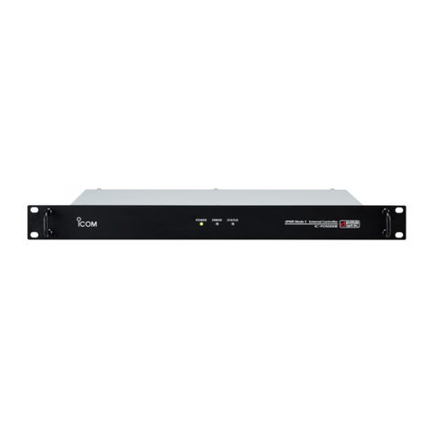
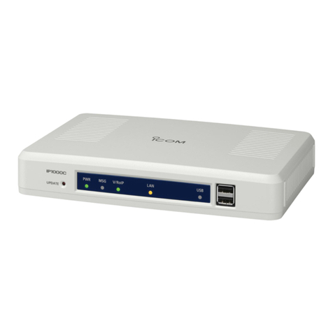
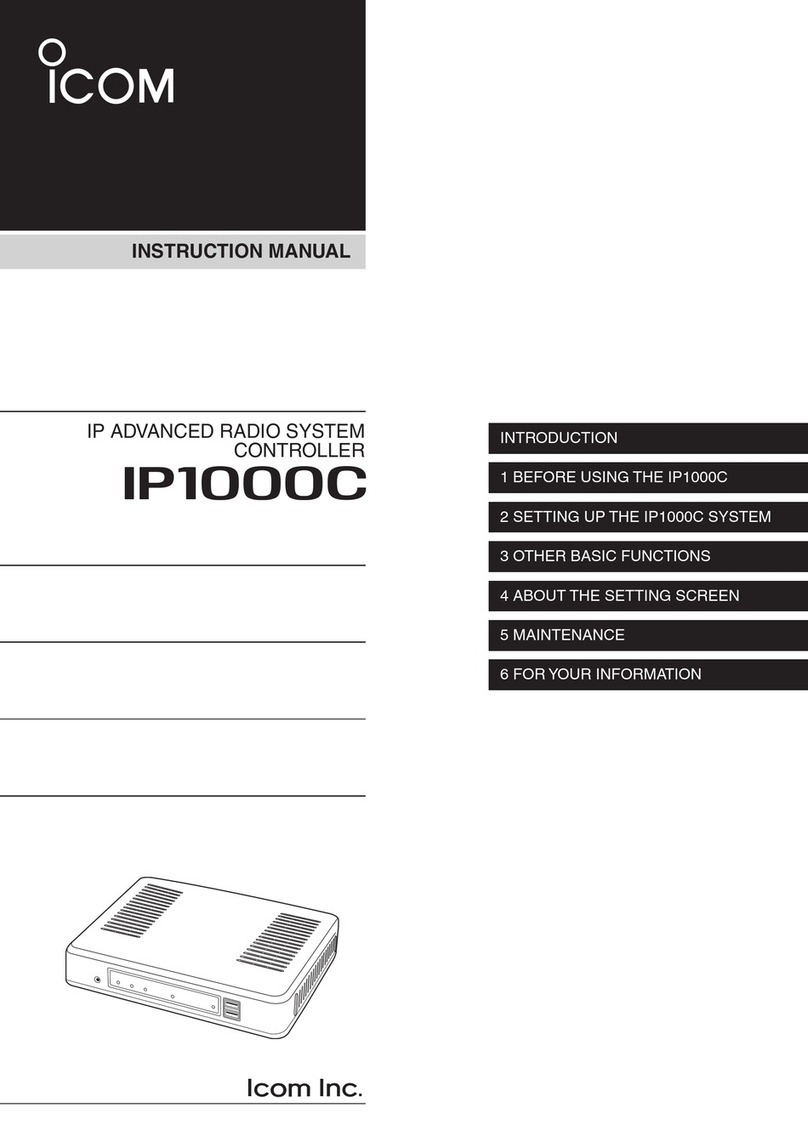
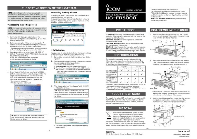
Icom IP1100CV User manual

i
INTRODUCTION
Thank you for choosing this Icom product.
The IP1100CV wlan transceiver controller is designed and built with Icom’s IP network technology.
We hope you agree with Icom’s philosophy of “technology rst.” Many hours of research and development
went into the design of your IP1100CV.
ALL RIGHTS RESERVED. This document contains material protected under International and Domestic
Copyright Laws and Treaties. Any unauthorized reprint or use of this material is prohibited. No part of
this document may be reproduced or transmitted in any form or by any means, electronic or mechanical,
including photocopying, recording, or by any information storage and retrieval system without express written
permission from Icom Incorporated.
All stated specications and design are subject to change without notice or obligation.
Icom and the Icom logo are registered trademarks of Icom Incorporated (Japan) in Japan, the United States,
the United Kingdom, Germany, France, Spain, Russia, Australia, New Zealand, and/or other countries.
Microsoft and Windows are trademarks of the Microsoft group of companies.
AMBE+2 is a trademark and property of Digital Voice Systems Inc.
The Bluetooth word mark and logos are registered trademarks owned by the Bluetooth SIG, Inc. and any use
of such marks by Icom Inc. is under license.
Other trademarks and trade names are those of their respective owners.
Icom is not responsible for the destruction, damage to, or performance of any Icom or non-Icom equipment,
if the malfunction is because of:
• Force majeure, including, but not limited to, res, earthquakes, storms, oods, lightning, other natural
disasters, disturbances, riots, war, or radioactive contamination.
• The use of Icom transceivers with any equipment that is not manufactured or approved by Icom.

ii
INTRODUCTION
Features
• The IP1100CV wlan transceiver controller enables you to communicate wireless LAN transceivers that are
connected to the Controller through IP networks.
• A total of up to 300 WLAN transceivers and IP100FSs remote communicator can be registered and used in
the IP1100CV system.
• Enables emergency calls to linked transceivers, and monitors unusual operation of the linked transceivers.
• A USB ash drive can be connected to the USB port for such as recording the audio communication between
WLAN transceivers, updating the rmware and backing up or restoring the settings.
• Enables a bridge connection to the VE-PG3.
• Supports SNMP for network management.
• IP ltering function that restricts access from unknown network addresses.
• Automatic switching between 2.5GBASE-T, 1000BASE-T, and 100BASE-TX.
• Mountable into a 19 inch rack by installing the optional mounting bracket.
About the construction of the manual
You can use the following manuals to understand and operate this Controller.
Precautions (Comes with the Controller)
Instructions for the connections, initialization, and precautions.
Installation guide (This manual, PDF type)
Instructions for the system requirements, the system setup basics, maintenance, and the specications.
It can be downloaded from the Icom website.
Operating guide (PDF type)
The detailed references for the settings in the Controller Setting screen.
It can be downloaded from the Icom website.
Also refer to the manual for each device, that is connected to your system.
• The screen captures in this manual are examples of using Windows 10.
• In this manual, the IP1100CV is described as “Controller.”
• This document is described based on the IP1100CV rmware version 1.08.

iii
INTRODUCTION
Menu Item Screen Setting Item Option Value
Network Settings IP Address IP Address IP Address 192.168.0.1
Subnet Mask 255.255.255.0
DHCP Server DHCP Server DHCP Server Disable
Router Settings WAN Connection Type Connection Type Not used
Management Administrator Administrator Password Username admin (xed)
Current Password: –
Network and system default settings
LSee the Operating guide for more details on above settings.
LThe Administrator’s Username (admin) cannot be changed.
To prevent unauthorized access
You must be careful when choosing your password.
• Choose one that is not easy to guess.
• Use numbers, characters, and letters (case sensitive).
Conrming the MAC address
The MAC address of the built-in WAN or LAN module of the IP1100CV is shown on the Serial label at the
bottom of the product.
LYou can also check the MAC address on the setting screen. See the Operating guide for details.
The contents of the serial label may vary,
depending on the version.
Serial label
IP1100CV (Bottom)
0090C7
0090C7
MAC address for LANMAC address for LAN
MAC address for WANMAC address for WAN

1-1
Section
BEFORE USING THE CONTROLLER 1
Panel description ……………………………………………………………………………………………………… 1-2
■Front panel ……………………………………………………………………………………………………… 1-2
■Rear panel ……………………………………………………………………………………………………… 1-4
■Side panel………………………………………………………………………………………………………… 1-5
Feature description …………………………………………………………………………………………………… 1-6
■Controlling wireless LAN transceivers ………………………………………………………………………… 1-6
■Simplex and Full-Duplex communication …………………………………………………………………… 1-7
■The VOX function ……………………………………………………………………………………………… 1-7
■Multiple communication ………………………………………………………………………………………… 1-7
■All Calls and Group Calls ……………………………………………………………………………………… 1-8
■Talkgroup Calls ………………………………………………………………………………………………… 1-9
■Individual Call ………………………………………………………………………………………………… 1-10
■Calling mode ………………………………………………………………………………………………… 1-10
■Priority Call and its priority …………………………………………………………………………………… 1-11
■Area calls ……………………………………………………………………………………………………… 1-12
■Messages ……………………………………………………………………………………………………… 1-13
■Status Settings………………………………………………………………………………………………… 1-14
■The Router function ………………………………………………………………………………………… 1-15
■The VPN function …………………………………………………………………………………………… 1-15
Installation and connections ……………………………………………………………………………………… 1-16
■Attaching the magnetic legs ………………………………………………………………………………… 1-16
■Setting a static IP address to a PC ………………………………………………………………………… 1-17
■Connecting the cables and the PC ………………………………………………………………………… 1-18
The Setting screen ………………………………………………………………………………………………… 1-19
■Accessing the setting screen………………………………………………………………………………… 1-19
■Setting screen description …………………………………………………………………………………… 1-20
■Changing the IP address on the setting screen …………………………………………………………… 1-21

1BEFORE USING THE CONTROLLER
1-2
■Front panel
Panel description
INDICATORS
1[POWER] �������� Lights green: Power is ON
Blinks green: Booting up
Lights orange: Boot loader is booting
Lights red: Boot loader prompt stopped
Blinks red: UID indication
LUsed for identication purpose by administrator
(operation on the web) in such case as 2 or more
IP1100CVs are installed in a system.
Not lit: Condition other than the above
2[MSG] ��������� Lights green: (Online update) A firmware update is ready.
Blinks green: Initialization is in progress/
(Online update) Firmware update is in progress
Not lit: Condition other than the above
3[ADVANCE] ������� Reserved for future function.
Not lit: Any condition
4[USB]���������� Lights green: A USB flash drive is mounted
Blinks green: Accessing the USB flash drive
Lights red: Failed updating the firmware/
Failed reading from a USB flash drive
Not lit: A USB flash drive is unmounted or not connected
5[VPN] ���������� Lights green: At least one IPsec tunnel has been established
Not lit: Not connected/VPN not used/Invalid setting
6[V/RoIP] �������� Lights green: At least one WLAN transceiver has been
successfully registered
Not lit: Condition other than the above
7[WAN] ��������� Lights green: Connected to a WAN/
(PPPoE) PPP has been established/
(DHCP client) IP address obtained/
Lights red: (PPPoE) Authentication failure/
(DHCP client) Failed to obtain an IP address
Not lit: Condition other than the above
8[LAN] ���������� Lights green: Connected to a LAN
Not lit: Condition other than the above
1 8 9 234567

1BEFORE USING THE CONTROLLER
1-3
Panel description
■Front panel
9<UPDATE> BUTTON ��� When [MSG] lights green, a firmware update is ready. Hold down this
button until [MSG] blinks green to update the firmware.
LUse a pin to push the button.
<INIT> BUTTON ����� Push to initialize the settings. See Section 3 for details.
LUse a pin to push the button.
<USB EJECT> BUTTON � When removing the USB flash drive, hold down this button until
[USB] (4) turns OFF.
[USB] PORT
(USB 3.0) �������� Connect a USB flash drive (user supplied) to save or restore settings or
to update the firmware.
LYou can save the recorded audio on a data storage device through the USB
port. Only one storage device can be connected to the USB port at a time.
LBe sure to back up the data on the USB ash drive before connecting it to
the Controller.
LA USB ash drive, such as one with biometric authentication, or one with
password protection is not supported.
LSome USB devices may not be usable with the IP1100CV.
[CONSOLE] PORT
(USB Type-C) ������ Connect a USB (Type-C) cable (user supplied) to remotely configure
the Controller from a PC using a terminal software (user supplied.)
About the USB driver
To use the [CONSOLE] port, the USB driver for the Icom network
devices is required.
Download the USB driver from the Icom website and install it on your
PC.
https://www.icomjapan.com/support/
1 8 9 234567

1BEFORE USING THE CONTROLLER
1-4
■Rear panel
Panel description
1[GND] TERMINAL ���� Connect to ground.
2[DC] JACK ������� Connect the supplied power adapter.
3[LAN] PORT
(RJ-45 type) ������� Connect a network device such as a Switch.
Lights: Connected
Blinks: Communicating
qGreen: 1000BASE-T/2.5GBASE-T
wOrange: 100BASE-TX
qw
4[WAN] PORT
(RJ-45 type) ������� Connect a bridge modem (ADSL, VDSL, or CATV) or FTTH terminal.
Lights: Connected
Blinks: Communicating
qGreen: 1000BASE-T/2.5GBASE-T
wOrange: 100BASE-TX
qw
LTo use the [WAN] port, the [Line Type] setting is required.
(Router Settings > WAN > Connection Type)
See the Operating guide for details.
1 3 4
2

1BEFORE USING THE CONTROLLER
1-5
Panel description
■Side panel
1
1Security slot ������ Attach a security wire (user supplied).
Refer to the instruction manual that comes with the security wire for
details.

1BEFORE USING THE CONTROLLER
1-6
■Controlling wireless LAN transceivers
You can communicate through IP networks using the IP1100CV as a controller for up to 300 WLAN
transceivers.
LA wireless access point is required.
LThe IP100H, IP110H, and IP100FS are usable, as of June, 2023.
IP1100CV Wireless access point
IP100FS
(Remote communicator) IP100HIP110H
IP100FS (Remote communicator)
The IP100FS enables you to remotely communicate with WLAN transceivers connected to your IP1100CV
from a PC through an IP network.
• See the IP100FS software help for more details.
IP110H (WLAN transceiver)
IP110H enables you to communicate using the IP1100CV and a wireless access point through an IP network.
• Verify the proper system formation according to your system environment, and then the WLAN transceiver conguration,
wireless LAN settings, and server settings using the CS-IP110H are required.
• See the IP110H instruction manual for more details.
CS-IP110H (Programming software)
The CS-IP110H programming software is used for data entry, setting, and programming for the IP110H with a
PC. You can download the free software and its manual from the Icom website.
• To communicate the IP110H and your PC, connect them with the USB cable supplied with the IP110H. See the
CS-IP110H instruction manual for details.
IP100H (WLAN transceiver)
IP100H enables you to communicate using the IP1100CV and a wireless access point through an IP network.
• Verify the proper system formation according to your system environment, and then the WLAN transceiver conguration,
wireless LAN settings, and server settings using the CS-IP100H are required.
• See the IP100H instruction manual for more details.
CS-IP100H (Cloning software)
The CS-IP100H programming software is used for data entry, setting, and programming for the IP100H with a
PC. You can download the free software and its manual from the Icom website.
• To communicate the IP100H and your PC, the optional programming cable is required. See the CS-IP100H instruction
manual for details.
Feature description

1BEFORE USING THE CONTROLLER
1-7
Feature description
■Simplex and Full-Duplex communication
The Controller has two methods of communication, Simplex and Full-Duplex.
Simplex is for communications where receive and transmit are done alternately one by one, and Full-Duplex is
for simultaneous receive and transmit just like a telephone call.
Set the Communication Method in “Transceiver Settings” for each IP communication terminal registered to the
IP1100CV.
IP110H
IP1100CVSimplex and Full-Duplex
Wireless
access point
■The VOX function
The VOX function allows you a hands-free operation. The VOX function starts transmission when you speak
into the microphone, without needing to push [PTT]; then, automatically returns to reception when you stop
speaking.
LTo use the VOX function, an optional headset (and connection cable, depending on the headset) are required. See the
WLAN transceiver’s manual for details.
■Multiple communication
WLAN transceivers can simultaneously make multiple communications in an IP1100CV system since crosstalk
does not occur in an IP network.
IP1100CV Wireless access point
Group call
Individual callIndividual call
IP100H
IP110H

1BEFORE USING THE CONTROLLER
1-8
Feature description
■All Calls and Group Calls
All Calls are used to call all the WLAN transceiver and IP100FS that are registered on the [Transceiver
Registration] screen.
(Transceiver Controller > Transceiver Settings > Transceiver Registration)
Group Calls are used to call a group of WLAN transceivers and IP100FS.
You can make a group on the [Destination Settings] screen, and pick up IDs from the ID List that you want to
register into the group.
(Destination Settings > Destination Settings)
LThe ID List and the destination settings set in the IP1100CV are commonly used in each group that the WLAN
transceivers and IP100FS belong to.
You can select Simplex or Full-Duplex communication for All Calls and Group Calls.
Simplex operation
• The called station cannot reply until the caller station stops transmitting.
IP110H
IP1100CV
Wireless
access point
IP100FS
(Remote communicator)
Full-Duplex operation
• Caller and called stations can simultaneous receive and transmit just like a telephone call.
IP110H
IP1100CV
Wireless
access point
IP100FS
(Remote communicator)

1BEFORE USING THE CONTROLLER
1-9
Feature description
■Talkgroup Calls
Talkgroup Calls enables WLAN transceivers to select the group that belong to it from previously registered
groups in the IP1100CV.
When users select Talkgroup 01000, terminals are excluded from the original groups, as illustrated below.
• Talkgroup Calls require registering the Talkgroups in the [Destination Settings] screen and [ID List] screen. If the
“Talkgroup Type” in the [Destination Settings] screen is set to “Multiplex Talkgroup,” a WLAN transceiver can make a
Talkgroup Call between the linked Talkgroups.
(Transceiver Controller > Common Settings > ID List)
(Destination Settings > Destination Settings > Destination Settings > Talkgroup Type*)
*Displayed only when [Call Type] is set to “Talkgroup.”
• Set to the Controller whether All Call includes the Talkgroup or not, or the Talkgroup Call calls the IP100FS or not.
• The ID List and the destination settings set in the Controller are commonly used in each group that the WLAN transceiver
and IP100FS belong to.
Group 00100
All
Group 00101
Talkgroup 01000 Talkgroup 01001
00001 00002 00003 00004 00006 00007 00008 00009
Group 00100
All
Group 00101
Talkgroup 01000 Talkgroup 01001
00001 00002 00003 00007 00008
00004
00006
00009
When no Talkgroup is selected:
When a Talkgroup is selected:

1BEFORE USING THE CONTROLLER
1-10
Feature description
■Individual Call
Individual Calls are used to talk to a transceiver 1 on 1.
When an Individual call is made, the WLAN transceiver displays the connection status. (Connected, Busy, or
No response)
LIf the destination that you are calling is out of range, “No response” is displayed.
LSet the Receive Notication Tone on the [Prole] screen to notify a connection status, if necessary.
(Transceiver Controller > Common Settings > Prole)
IP1100CV
Wireless access point
Individual call
IP110H
Sales 1 Sales 2
■Calling mode
When you are receiving or transmitting, the transceiver enters the calling mode.
While in the calling mode (until the Talkback Timer elapses,) you can communicate to the destination only with
the transmitting operation.
About TalkBack Timer
The TalkBack timer starts when the calling transceiver nishes transmitting until the transceiver returns to the
standby mode. (Default: 5 seconds)
About the communication priority while in the TalkBack Timer
If a new call has arrived while in the TalkBack Timer, it is accepted according to the call priority.
The transceiver accepts incoming calls with a higher priority than the current call, but not lower or equal
priority. The incoming call will be accepted after the TalkBack Timer has elapsed.
The Talkback Timer set in the Controller is shared in each setting group to that the WLAN transceiver belongs.
Wireless
access point
Individual Call from
Sales 1 to Sales 2
has arrived
Enters Calling
mode
IP1100CV
IP110H
Sales 1 Sales 1
Sales 2 Sales 2
Sales 3
Sales 3
Regular Individual Call
destination: Sales 3 The destination changes from
Sales 3 to Sales 1
Selecting an Individual Call
(Example: Sales 1 calling Sales 2)
Displays the
connection status

1BEFORE USING THE CONTROLLER
1-11
Feature description
■Priority Call and its priority
The Priority Call function is set to “Disable” in the default setting.
The priority levels of the Call types are in the following order.
Priority level Priority Call type Priority Call Remarks
High
Fixed
Telephone — For telephone communication
Emergency (High) Enable —
Emergency (Normal) Disable —
Selectable*
All Call (High) Enable Includes the Area Call or calling from an IP100FS
Individual Call (High) Enable Includes from an IP100FS
Group Call (High) Enable Includes the Area Call or calling from an IP100FS
All Call (Normal) Disable Includes the Area Call
Individual Call (Normal) Disable —
Low Group Call (Normal) Disable Includes the Area Call
* Selectable in the Call Type Priority item on the [RoIP Server] screen.
(Transceiver Controller > RoIP Server Settings > RoIP Server)
• The call priority between the same priority level depends on the incoming order.
• The priority of the reply call depends on the caller’s priority level.
Priority call interruption example:
IP1100CV
IP110H
Wireless
access point
Group call
Individual call
An Individual call
(high priority) has
arrived

1BEFORE USING THE CONTROLLER
1-12
Feature description
■Area calls
Area calls are used to call WLAN transceivers in a specic area. (Default: Disable)
To use Area Call function, enable [Area Call] for each WLAN transceiver on the Transceiver Settings screen,
and then register the area’s wireless access point (BSSID).
(Transceiver Controller > Transceiver Settings > Transceiver Settings > Function Settings > Area Call)
(Transceiver Controller > RoIP Server Settings > Area Call > Area Setting)
Making an All Call with the Area Call function
(For the IP100FS) Making an All Call with the Area Call function
IP110H
Wireless
access point
Sales Accounts Parts
All call
IP1100CV
Select wireless access points
(for example, Sales and
Accounts) that the IP110H uses
to make Area calls, on the [Area
Call] screen.
On the IP100FS, you can make
an Area Call to the WLAN
transceivers that belongs to the
specied wireless access point.
Select an access point in
[Location], and then Call Type
(Individual, Group, All, Area, or
Telephone) and the name of the
destination will be displayed.

1BEFORE USING THE CONTROLLER
1-13
Feature description
■Messages
The Messages function enables you to communicate with preset messages of up to 32 characters between WLAN
transceivers and IP100FS. (Default: Disable)
You can register up to 10 messages to the IP1100CV on the [Messages] screen.
(Transceiver Controller > Common Settings > Messages)
Example: Sending a message with All Call
• To use the Messages function, enable the [Message] on the [Transceiver Settings] screen for each WLAN
transceiver.
• The messages that are registered to the Controller are commonly used by the WLAN transceivers that
belong to the setting group.
The IP100FS can store up to 100
messages in each site.
You can edit the stored messages.
IP1100CV
IP110H
Wireless
access point Blinks
Scrolls
Message select screen
(Sender)
Displays Call Type Selected or edited message
Received Message screen
(Destination)
All call

1BEFORE USING THE CONTROLLER
1-14
Feature description
■Status Settings
The Status function is used to show your status information (Example: Meeting). (Default: Disable)
• You can preset 10 status texts of up to 32 characters on the [Status] screen.
(Transceiver Controller > Common Settings > Status)
Sending status on the IP110H
Status selection screen
(Sender)
Wireless
access point
Displays Name, Destination ID, Status
number, and the Status information
IP1100CV
IP110H
On the IP1100CV
On the Controller, you can check the Status of each WLAN transceiver on the [Transceiver Management]
screen. (Transceiver Controller > Transceiver Management)
On the IP100FS, One-Touch button

1BEFORE USING THE CONTROLLER
1-15
Feature description
■The Router function
When the router function of the IP1100CV is enabled, the devices such as PCs that are connected to the
IP1100CV can access the Internet. (Default: Disable)
LTo use the router function, set the [Connection Type] (DHCP Client, Static IP, or PPPoE) and detailed settings according
to your Internet environment. Ask your Internet service provider (ISP) or network administrator for details.
(Router Settings > WAN > Connection Type)
■The VPN function
VPN (Virtual Private Network) enables a host computer to send and receive data over the shared or public
networks like the Internet as if it were a private network. (Default: Disable)
The VPN function on the IP1100CV is compatible with the VE-PG4. (As of June, 2023)
LTo use the VPN function, connect the WAN line to the [WAN] port, and then congure the IPsec tunnel.
(Router Settings > VPN IPsec Tunnel Settings)
Internet
Head ofce Branch
IP1100CV
IP1100CV
IPsec tunnel
Key exchange protocol: IKEv2
Encryption algorithm: AES
Authentication algorithm: HMAC-SHA-2

1BEFORE USING THE CONTROLLER
1-16
■Attaching the magnetic legs
You can the supplied 4 magnetic legs on the bottom panel, and tighten the supplied screws to x them.
LNever use other than the supplied screws.
Installation and connections
Screw (supplied)
Magnetic leg
(supplied)
Table of contents
Other Icom Controllers manuals
Popular Controllers manuals by other brands

FISNAR
FISNAR DSP501N operating manual

intelliConsole
intelliConsole IC200 quick start guide

Intuitive Aerial
Intuitive Aerial Newton S2 3G System operation manual

Generac Power Systems
Generac Power Systems Power Zone Pro owner's manual

Azoteq
Azoteq IQ Switch - ProxSense Series quick start guide

Eaton
Eaton xComfort CSAU-01/03 Assembly instructions