manuals.online logo
Brands
  1. Home
  2. •
  3. Brands
  4. •
  5. Icom
  6. •
  7. Controllers
  8. •
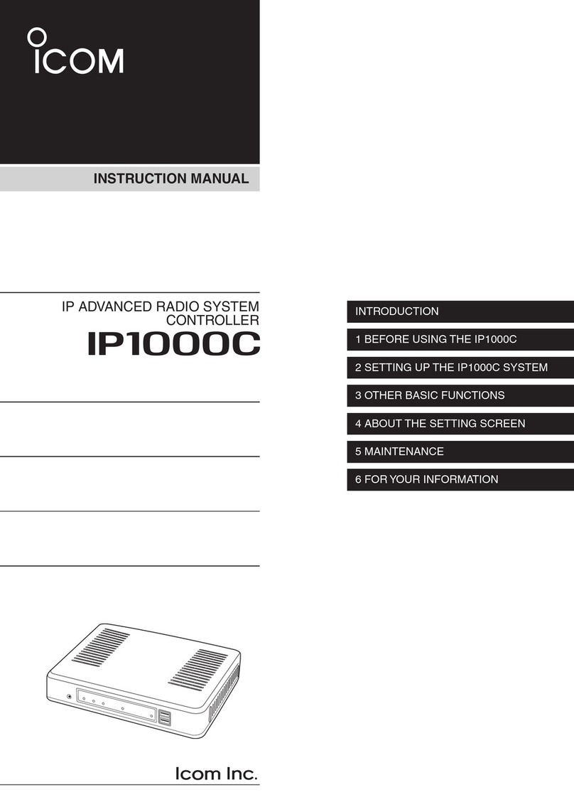
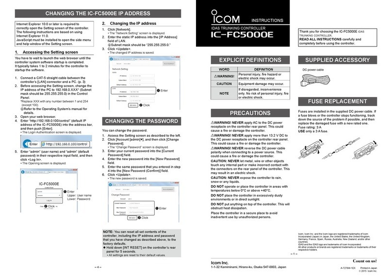
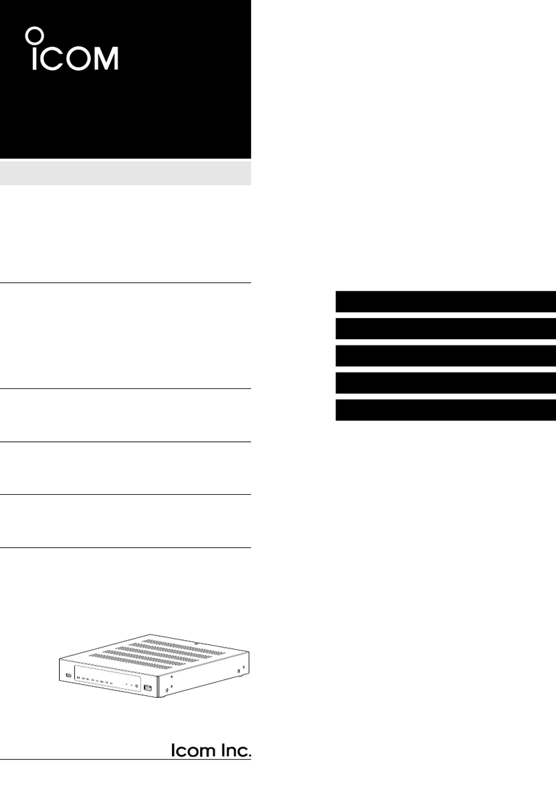
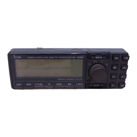
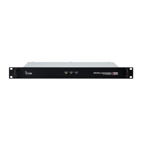
  9. Icom IP1000C User manual

Icom IP1000C User manual

INSTRUCTION MANUAL
IP1000C
IP ADVANCED RADIO SYSTEM
CONTROLLER INTRODUCTION
1 BEFORE USING THE IP1000C
2 SETTING UP THE IP1000C SYSTEM
3 OTHER BASIC FUNCTIONS
4 ABOUT THE SETTING SCREEN
5 MAINTENANCE
6 FOR YOUR INFORMATION
i
INTRODUCTION
Thank you for choosing this Icom product. The IP1000C ip advanced radio system controller is designed and
built with Icom’s IP network technology.
We hope you agree with Icom’s philosophy of “technology rst.” Many hours of research and development
went into the design of your IP1000C.
ALL RIGHTS RESERVED. This document contains material protected under International and Domestic
Copyright Laws and Treaties. Any unauthorized reprint or use of this material is prohibited. No part of
this document may be reproduced or transmitted in any form or by any means, electronic or mechanical,
including photocopying, recording, or by any information storage and retrieval system without express written
permission from Icom Incorporated.
All stated specications and design are subject to change without notice or obligation.
Icom and the Icom logo are registered trademarks of Icom Incorporated (Japan) in Japan, the United States,
the United Kingdom, Germany, France, Spain, Russia, Australia, New Zealand, and/or other countries.
Microsoft and Windows are trademarks of the Microsoft group of companies.
3M, PELTOR, and WS are trademarks of 3M Company.
The Bluetooth®word mark and logos are registered trademarks owned by the Bluetooth SIG, Inc. and any use
of such marks by Icom Inc. is under license.
Other trademarks and trade names are those of their respective owners.
ii
INTRODUCTION
FEATURES
• The IP1000C enables you to communicate through IP networks by using the IP1000C as a controller for the
Icom Wireless LAN transceivers IP100H and IP110H (described as “WLAN transceivers” in this manual.)
- A wireless access point is required.
IP100FS
(Remote Communicator
)
IP1000C
Wireless
access
point
Connection example
IP
Network
IP100H
• A total of up to 100 WLAN transceivers and IP100FSs remote communicator can be registered and used in
the IP1000C system. (Depending on the IP1000C versions, only 20 terminals can be registered.)
- The IP100FS enables you to remotely communicate with WLAN transceivers connected to your IP1000C
from a PC through an IP network.
• The IP1000C has two methods of communications (Simplex and Full-Duplex.)
- The Simplex is for communications where receptions and transmissions are done alternately one by one,
and the Full-Duplex is for simultaneous receptions and transmissions as a telephone call.
• The call types are All Call, Group Call, Talkgroup Call, Individual Call, and Telephone Call.
- The Talkgroup Call is the terminal selects the group that it belongs to.
• In the All Call, Group Call and Talkgroup Call, you can assign the simplex or full-duplex mode to the each
calls.
• The Area Calls can be operated by limiting to a certain area.
• If you connect with Icom’s VE-PG3 (ver. 1.13 or later), you will be able to communicate with certain types of
Icom transceivers.
Also If you connect in bridge port with Icom’s VE-PG3 (ver. 1.03 or later), you will be able to communicate
using the VoIP router, which enables you make extension phone calls and outline phone calls.
Only the VE-PG3’s bridge ports that are set in the converter mode are connectable.
• A total of up to 50 ID list and 10 messages can be programmed for each setting group.
• Status settings can be programmed to send the status information (Example: Away from the desk) from the
WLAN transceiver.
- Up to 10 statuses can be programmed.
• The settings congured with the IP1000C is automatically set when the WLAN transceiver is turned ON.
• Automatic rmware updates for the WLAN transceivers can be done using the IP1000C.
• The LAN ports automatically select from 10BASE-T, 100BASE-TX or 1000BASE-T, and detect the port
polarity type between MDI (straight) and MDI-X (crossover), depending on the connected devices.
• The [LAN] port is equipped with 4-port switching HUB.
• Supports SNMP as the network management.
• Automatic Restore using a USB ash drive.
• You can communicate with IP100Hs connected to the additional IP1000Cs on the network by using the
[Additional Controller Link] function.
- Use a VPN router such as Icom’s SR-VPN1 between sites, if necessary.
LThis document is described based on the IP1000C rmware version 2.48.
iii
INTRODUCTION
OPTIONS As of June 2023
OPC-1402A
Maintenance cable
IP100FS
remote communicator
IP100FS enables you to remotely communicate
with WLAN transceivers connected to your
Controller from a PC through an IP network.
NOTE:
Approved Icom optional equipment is designed for optimal performance when used with an Icom
transceiver.
Icom is not responsible for the destruction or damage to an Icom device in the event the Icom device is used
with equipment that is not manufactured or approved by Icom.
Menu Item Setting Window Setting Item Item Name Value
Network Settings IP Address IP Address IP Address 192.168.0.1
Subnet Mask 255.255.255.0
DHCP Server DHCP Server DHCP Server Disable
Management Administrator Administrator Username admin (xed)
Current Password: admin (lower case)
Date and Time NTP NTP Client Enable
SNTP Server SNTP Server Enable
USB USB
USB Flash Drive Enable
USB Access
Permission
✓Firmware Update
✓Backup/Restore
Firmware Update Automatic Update Automatic Update Enable
NETWORK AND SYSTEM DEFAULT SETTINGS
LSee the Section 4 for more details on above settings.
LThe Administrator’s Username (admin) cannot be changed.
To prevent unauthorized access
• You must choose a strong password.
• Choose one that is not easy to guess.
• Use numbers, characters and letters (both lower and upper case).
iv
INTRODUCTION
SETTING PROCEDURE
Set up the IP1000C, following the procedure below.
▼
▼
▼
▼
Step.1
Step.2
Step.3
Step.4
Step.5
Access the setting screen CONNECTION GUIDE/Section 2
Connect to a PC and turn ON the power CONNECTION GUIDE
Configuring the network connection pp. 4-11, 4-12
Registering the terminals pp. 2-5, 2-6
Configuring the settings for each terminals p. 2-7
▼
Step.6 Registering the terminals to a group p. 2-8
▼
Step.7 Configuring the settings for groups pp. 2-9 to 2-13
1-1
BEFORE USING THE IP1000C Section 1
1. Panel description …………………………………………………………………………………………………… 1-2
MFront panel ……………………………………………………………………………………………………… 1-2
MRear panel ……………………………………………………………………………………………………… 1-4
2. Feature description ………………………………………………………………………………………………… 1-5
MAbout the basic connection …………………………………………………………………………………… 1-5
MConnecting transceivers………………………………………………………………………………………… 1-6
MConnecting a telephone and transceivers …………………………………………………………………… 1-6
MSimplex and Full-Duplex ……………………………………………………………………………………… 1-7
MMulti communication …………………………………………………………………………………………… 1-7
MAll Call and Group Call ………………………………………………………………………………………… 1-8
MTalkgroup Call …………………………………………………………………………………………………… 1-9
MIndividual Call ………………………………………………………………………………………………… 1-10
MCalling mode ………………………………………………………………………………………………… 1-10
MPriority Call and its priority …………………………………………………………………………………… 1-11
MArea Call ……………………………………………………………………………………………………… 1-12
MMessages ……………………………………………………………………………………………………… 1-13
MAbout Status Settings………………………………………………………………………………………… 1-14
1BEFORE USING THE IP1000C
1-2
1. Panel description
■Front panel
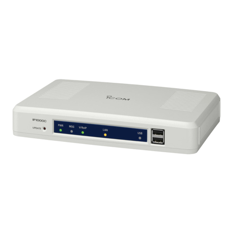
1[UPDATE] button ���� When [MSG] lights green, a firmware update is ready.
To download and install the new firmware, hold down this button until
[MSG] blinks.
• To use the Firmware Update function, an internet connection, DNS and
default gateway settings are necessary.
2[PWR] ��������� Not lit: Power is OFF
Lights green: Power is ON*1
Blinks green: Booting*1*2
Lights orange: Booting*1
Blinks orange: Booting*1*2
*1After the power is ON:
Blinks green > lights orange > blinks orange > lights green
*2After [INIT] is pushed until the default resets are completed:
Blinks orange and green alternately.
3[MSG] ��������� Not lit: The latest firmware is installed
Lights green: A firmware update is ready (Online update)
Blinks green: Downloading new firmware (Online update)
4[V/RoIP] �������� Not lit: No registration
Lights green: IP communication terminal registered
(More than 1 registration)
5[LAN]*3*4�������� Not lit: Not connected
Lights green: LAN connected: All connections (1000BASE-T)
Lights orange: LAN connected: More than 1 connection
(10BASE-T/100BASE-TX)
*3When 1000BASE-T/10BASE-T/100BASE-TX are mixed, the [LAN] LED lights
orange.
*4The data communication status for each [LAN] port can be checked with the
[LAN] LED on the rear panel. (p. 1-4)
1 2 3 4 5 6 7
1BEFORE USING THE IP1000C
1-3
1. Panel description
■Front panel
6[USB]���������� Not lit: A USB flash drive is not inserted.
Lights green: Inserting an USB flash drive.
Blinks green: Accessing the USB flash drive*5
Blinks orange: Accessing the USB flash drive*5
*5While accessing (resetting or firmware updating) the USB flash drive, this
LED alternately blinks green and orange.
7[USB] ports
(USB2.0×2) ������� If you insert the USB flash drive, the automatic load function for setting
data can be used. When using the USB flash drive, detach the supplied
power adapter, and then securely insert the USB flash drive into the
[USB] port.
LIcomisnotresponsibleforallthedevicesusedwiththeUSBashdrive.
Using the Automatic Setting data upload with a USB flash drive
Insert a USB flash drive (purchase separately) to recover the
configuration or to update the firmware. (p. 5-9)
• TurnOFFtheIP1000C’spowerbeforeinsertingorremovingtheUSBash
drive, to prevent data corruption.
• EitheroneoftheUSBslotsacceptsaUSBashdrive,butinsertonlyone
drive at a time.
• SecurelyinserttheUSBashdrive.
• NEVERremovetheUSBashdriveorturnOFFtheIP1000C’spower,while
transferringdata.Itwillcausedatacorruption,ordamagetheUSBashdrive.
• Afterthermwareupdatingiscompleted,checkthermwareversiononthe
setting window to verify that the update was correctly done.
• WhenimportingsettingdatafromtheUSBashdrivetotheIP1000C,the
originally programmed setting data is automatically saved as “bakdata.sav” on
theUSBashdrive,asabackup.
• AUSBashdrivesuchasonewithbiometricauthentication,oronewith
password protection is not supported.
1 2 3 4 5 6 7
1BEFORE USING THE IP1000C
1-4
1. Panel description
■Rear panel
1 2 3 4 5
1[CONSOLE] port
(RJ-11 type) ������� Connect an RS-232C serial communication interface to externally
configure the IP1000C. (Optional OPC-1402A is required.)
2[LAN] ports
(RJ-45 type×4)������ Connect the network devices such as a HUB.
[LED indication]
Lights:
Blinks:
qGreen:
w
Orange:
q w
LAN connected
LAN data communicating
1000BASE-T
10BASE-T/100BASE-TX
3[INIT] button ������ If you forget its IP address and you cannot access to the IP1000C
setting screen, you can initialize (reset) the IP1000C by pushing [INIT]
on the rear panel. (p. 5-4)
• Seethe“PRECAUTIONS”leaetfordetails.
• Initializing resets all settings to the factory defaults.
4DC jack ��������� Connect the supplied power adapter.
5Ground terminal����� Connect to the ground.
1BEFORE USING THE IP1000C
1-5
2. Feature description
■About the basic connection
The IP1000C enables you to communicate through IP networks by using the IP1000C as a Controller for the
WLAN transceivers.
• A wireless access point is required
• As of June 2023, the IP100H, IP110H, and IP100FS are available for the IP1000C client.
IP1000C Wireless access point
IP100FS
(Remote communicator)
IP100H IP110H
IP100H (WLAN transceiver)
IP100H enables you to communicate using the IP1000C and a wireless access point through IP networks.
• Verify the appropriate system formation according to the environment used, and then the IP communication terminal
conrmation,wirelessLANsettingsandserversettingsusingtheCS-IP100Harerequired.
• See the IP100H instruction manual for more details.
IP100FS (Remote communicator)
The IP100FS enables you to remotely communicate with WLAN transceivers connected to your IP1000C
from a PC through IP networks.
• SeetheIP100FShelpleformoredetails.
CS-IP100H (Cloning software)
The CS-IP100H cloning software is designed to be used for data entry, setting and programming for the
IP100H from a PC. (You can download the free software from the Icom’s website)
• Connect the cloning cables correctly according to the CS-IP100H instruction manual uploaded on the Icom’s website.
Read the instruction carefully and completely.
IP110H (WLAN transceiver)
IP110H enables you to communicate using the IP1000C and a wireless access point through IP networks.
• Verify the appropriate system formation according to the environment used, and then the IP communication terminal
conrmation,wirelessLANsettingsandserversettingsusingtheCS-IP110Harerequired.
• See the IP110H instruction manual for more details.
CS-IP110H (Programming software)
The CS-IP110H programming software is designed to be used for data entry, setting and programming for the
IP110H from a PC. (You can download the free software from the Icom’s website)
• Connect the programming cables correctly according to the CS-IP110H instruction manual uploaded on the Icom’s
website. Read the instruction carefully and completely.
1BEFORE USING THE IP1000C
1-6
2. Feature description
■Connecting transceivers
If you connect in controller connection with Icom’s VE-PG3 (ver. 2.01 or later), you will be able to
communicate with certain types of our transceivers.
IP1000C
VE-PG3
IP100H
Wireless access point
Controller connection
(RoIP Gateway)
[D-TRX1]
Transceiver
CT-24
[USB]
Repeater
P
0
P
1
P
2
P
3
P
4
LOnly the VE-PG3’s controller ports that are set as the bridge mode are connectable.
■Connecting a telephone and transceivers
If you connect in bridge connection with Icom’s VE-PG3 (ver. 1.13 or later), you will be able to communicate
with certain types of our transceivers and also, using the VoIP router enables you make extension phone calls
and outline phone calls.
IP1000C
VE-PG3
IP100H
Wireless access point
Bridge connection
(RoIP Gateway)
IP phone
[TRX1]
Transceiver
Transceiver
LOnly the VE-PG3’s bridge ports that are set as the converter mode are connectable.
1BEFORE USING THE IP1000C
1-7
2. Feature description
■Simplex and Full-Duplex
The IP1000C has two methods of communications (Simplex and Full-Duplex.)
The Simplex is for communications where receptions and transmissions are done alternately one by one, and
the Full-Duplex is for simultaneous receptions and transmissions as a telephone call.
Set the Communication Method in “Transceiver Settings” for each IP communication terminal registered to the
IP1000C.
• The Full-Duplex communications are done by connecting a microphone (purchase separately) to the IP100H.
• If no microphone is connected to the IP100H, the communication method is automatically set as Simplex.
Simplex
Simplex and Full-Duplex
Full-Duplex
IP1000C
IP100H
Wireless
access point
Connection cables Full-Duplex Simplex IP100H VOX function*1
(Set in the IP1000C)
Hands free PTT operation
HM-153 earphone microphone OPC-2144 ✓ ✓ —
HM-153LS earphone microphone —✓ ✓ —
HM-166 earphone microphone OPC-2144 ✓ ✓ —
HM-166LS earphone microphone —✓ ✓ —
HM-183LS speaker microphone —✓—
HM-186 speaker microphone OPC-2144 ✓—
HM-186LS speaker microphone —✓—
HS-85
(Discontinued product)
vox unit OPC-2144 ✓ ✓ ✓ Disable*2
HS-94 headset OPC-2006LS ✓Enable
HS-95 headset OPC-2006LS ✓Enable
HS-97 throat microphone OPC-2006LS ✓Enable
HS-102 headset OPC-2359*3 ✓ ✓ ✓ Enable
*1 When a headset that supports the VOX function is connected, the communication mode automatically changes
between reception and transmission by verifying the communication voice.
*2 Select [VOX] on the HS-85.
*3 Receive by using the OPC-2359.
■Multi communication
To prevent a crosstalk in the IP network, simultaneous multiple communications can be made in the system.
IP1000C
IP100H
Wireless
access point
Individual CallIndividual Call Group Call
1BEFORE USING THE IP1000C
1-8
10/8 16:57
All
Selecting All Call
10/8 16:57
Sales Group1
Selecting Group Call
Simplex operation
• When the Simplex is selected, the called station cannot reply until the caller station
stops transmitting.
IP1000C
Wireless access point
IP100H IP100H IP100FS
(Remote communicator)
Full-Duplex operation
IP1000C
Wireless access point
IP100FS
(Remote communicator)
IP100H IP100H
About All Calls
The All Call function is used to call all the WLAN transceivers and IP100FS that are registered in the
Transceiver Registration window in the IP1000C.
About Group Calls
The Group Call function is used to call the desired group selected from the ID List.
• It is required to divide the registered WLAN transceivers and IP100FS in the [Transceiver Registration] screen into
groups in the [Destination Settings] screen.
• The ID List and the destination settings set in the IP1000C are commonly used in each group that the WLAN transceivers
and IP100FS belong to.
2. Feature description
■All Call and Group Call
Simplex or Full-Duplex communication can be set for the All Call and Group Call.
1BEFORE USING THE IP1000C
1-9
Group 00100
All
Group 00101
Talkgroup 01000
When Talkgroup is OFF
Talkgroup 01001
00001 00002 00003 00004 00006 00007 00008 00009
Group 00100
All
Group 00101
Talkgroup 01000
When Talkgroup is selected
Talkgroup 01001
00001 00002 00003 00007 00008
00004
00006
00009
• The Talkgroup Call is required to register the Talkgroups in the [Destination Settings] screen and [ID List] screen. If the
“Talkgroup Type” in the [Destination Settings] screen is set to “Multiplex Talkgroup,” the WLAN transceivers can make a
Talkgroup Call between the linked talkgroups.
• Set to the IP1000C whether All Call includes the Talkgroup or not, or the Talkgroup Call calls the IP100FS or not.
• The ID List and the destination settings set in the IP1000C are commonly used in each group that the WLAN transceivers
and IP100FS belong to.
2. Feature description
■Talkgroup Call
The Talkgroup Call function allows user to select the group that belong to it from previously registered groups
in the IP1000C.
When users select Talkgroup 01000, terminals are excluded from the original groups, as illustrated below.
1BEFORE USING THE IP1000C
1-10
2. Feature description
■Individual Call
Individual Call is when you talk to a desired transceiver 1 on 1.
When an individual call is made, the WLAN transceiver displays the connection result. (Connected, Busy, or No
response)
• If the destination that you are calling is out of range, “No response” is displayed.
• Ifdesired,settheReceiveNoticationToneinthe[CommonSettings]Screeninthe[CommonSettings]menutonotifya
Call is received.
IP1000C
IP100H
Sales 1
Sales 8
Wireless access
point
Individual Call
10/8 16:57
Connected
10/8 16:57
Sales 8
Selecting an Individual Call
(Example: Sales 1 calling Sales 8)
The display after
transmitting
■Calling mode
When you are receiving or transmitting, the transceiver is in the calling mode.
While in the calling mode, only the transmitting operation is needed to communicate with the transceiver
you are calling.
Individual Call
Sales 1
Calling mode
IP1000C
Wireless access
point
IP100H
Sales 2
Sales 3 Sales 1
Sales 2
Sales 3
Sales 1 to Sales 2
Regular Individual Call destination: Sales 3 While in the calling mode, the Individual
Call destination is changed to Sales 1.
About TalkBack Timer
TheTalkBacktimerstartswhenthecallingtransceivernishestransmittinguntilthescreenreturnstothe
standby mode. (Default: 5 seconds)
About blocking the communications while in the TalkBack Timer
If there are new calls while in the TalkBack Timer, it is set to receive the calls in the priority order. (p. 4-133)
• A call cannot be received if it has an equal or lower priority than the call you are now making. Calls will be received after
the TalkBack Timer.
• The TalkBack Timer that are commonly used by the WLAN transceivers belonged to the setting group is set in the
IP1000C.
1BEFORE USING THE IP1000C
1-11
2. Feature description
■Priority Call and its priority
The Priority Call function is set to “Disable” in the default setting.
The priority levels of the Call types are in the following order.
Priority level Priority Call type Priority Call Remarks
High
Fixed
Telephone — For telephone communication
Emergency (High) Enable —
Emergency (Normal) Disable —
Selectable*
All Call (High) Enable Includes the Area Call or calling from an IP100FS
Individual Call (High) Enable Includes from an IP100FS
Group Call (High) Enable Includes the Area Call or calling from an IP100FS
All Call (Normal) Disable Includes the Area Call
Individual Call (Normal) Disable —
Low Group Call (Normal) Disable Includes the Area Call
* Selectable in the Call Type Priority item in the [RoIP Server] screen in the [RoIP Server settings] menu. (p. 4-22)
• Thepriorityisgiventotherstcallbetweencallswiththesameprioritylevel.
• The reply call follows the priority level of the talk side.
Making an Individual Call
during communication
Group Call
Change the target during communication with the Priority Call function enabled
Group Call
Individual Call
IP1000C
IP100H
Wireless
access point
1BEFORE USING THE IP1000C
1-12
To use Area Call, it is required to enable the [Area Call] for each WLAN transceiver in the [Transceiver
Settings] screen, and then register the area’s wireless access point (BSSID) in the [Area Entry List].
All Call
IP100H makes an All Call with the Area Call function
IP100FS calls the All Call with the Area Call function
The wireless access points that the
IP100H is included in with the Area Call
function, are set on the [Area Call] screen
in the [RoIP Server Settings] menu.
(Example: For Sales and For Accounts)
When the IP100FS uses the Area Call
function, can call IP100Hs that are in the
communication range of the access points
assigned to the Area Call.
Select the access point in the [Location], the
Call type (Individual, Group, All, Area or
Telephone) and names are displayed
IP1000C
IP100H
Wireless
access point
Sales Accounts Parts
2. Feature description
■Area Call
This function is used when operating by limiting to a certain area. (Default: Disable)
If you make an All Call or Group Call when Area Call in the WLAN transceiver is set to ON, the WLAN
transceiver and IP100FS that are in the same area with the WLAN transceiver connected to the wireless
access point are called.
1BEFORE USING THE IP1000C
1-13
2. Feature description
■Messages
Set this function to send a message with the WLAN transceiver and IP100FS. (Default: Disable)
Thexedmessagesofupto32characterstosendcanbesetinthe[Messages]screenofthe[CommonSetting]
Menu. Up to 10 messages can be registered.
All Call
IP100H transmits a message
Message selection screen
(TX)
Received message screen
(RX)
IP100FS transmits a message
Selected Call type Selected or edited message
IP1000C
IP100H
Wireless
access point
1/25 12:57
All Gather imme
Blinks Scrolls
The IP100FS can store up to 100 messages
in the each Site.
You can edit the stored messages.
Message
All
Gather immedi
• To use this function, requires to enable the [Message] item in the [Transceiver Settings] screen for each
WLAN transceiver.
• The messages that are registered to the IP1000C are commonly used by the WLAN transceivers that belong
to the setting group.
1BEFORE USING THE IP1000C
1-14
2. Feature description
■About Status Settings
Set the Status to send the status information (Example: Away from the desk) from the WLAN transceiver.
(Default: Disable)
• The status information of up to 32 characters can be programmed in the [Status] screen on the [Common
Settings] menu. Up to 10 status can be programmed.
• The status information sent using the WLAN transceiver can be displayed in the One-Touch Button screen or
in the [Transceiver Management] screen on the [Transceiver Settings] menu.
To use this function, requires to enable the [Status] item in the [Transceiver Settings] screen for each WLAN
transceiver.
IP100H sends the Status
Status selection screen
(TX)
IP100FS One-Touch button
Status
At lunch
IP1000C T
ransceiver Management screen
IP1000C
IP100H
Wireless
access point
Name, Destination ID, Status number
and Status information
Status
2-1
SETTING UP THE IP1000C SYSTEM Section 2
1. Flow using the WLAN transceiver………………………………………………………………………………… 2-2
MPrepare for connection and settings ………………………………………………………………………… 2-2
MAbout the Setting procedures ………………………………………………………………………………… 2-2
2. Transceiver settings………………………………………………………………………………………………… 2-4
MRegistering the terminals ……………………………………………………………………………………… 2-5
MConfirming the registration and rebooting the WLAN transceiver ………………………………………… 2-6
MAbout the WLAN transceiver settings ………………………………………………………………………… 2-7
MAbout the Group calls…………………………………………………………………………………………… 2-8
MAbout the Talkgroup calls ……………………………………………………………………………………… 2-9
MAbout the ID list ……………………………………………………………………………………………… 2-10
MAbout messages ……………………………………………………………………………………………… 2-11
MAbout the status settings …………………………………………………………………………………… 2-12
MAbout commonly use the ID list and message in the group……………………………………………… 2-13
3. Bridge connection and Caller settings ………………………………………………………………………… 2-14
4. Additional controller link ………………………………………………………………………………………… 2-18
5. Additional controller link with VE-PG3 ………………………………………………………………………… 2-24

Other manuals for IP1000C

3

Other Icom Controllers manuals

Icom IC-900 User manual

Icom

Icom IC-900 User manual

Icom DS-100 User manual

Icom

Icom DS-100 User manual

Icom IP1000C User manual

Icom

Icom IP1000C User manual

Icom IP1000C User manual

Icom

Icom IP1000C User manual

Icom IC-FC5000E User manual

Icom

Icom IC-FC5000E User manual

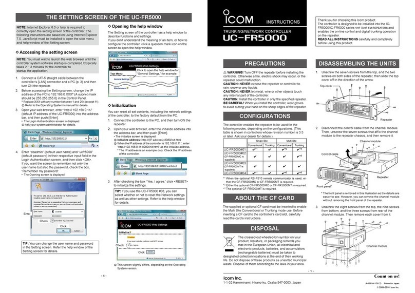
Icom UC-FR5000 User manual

Icom

Icom UC-FR5000 User manual

Icom IP1000C User manual

Icom

Icom IP1000C User manual

Icom IP1100CV User manual

Icom

Icom IP1100CV User manual

Icom IC-FC5000E User manual

Icom

Icom IC-FC5000E User manual

Popular Controllers manuals by other brands

Novy 906.270 installation instructions

Novy

Novy 906.270 installation instructions

Mebay ATS220 user manual

Mebay

Mebay ATS220 user manual

Jct JES-301K operating manual

Jct

Jct JES-301K operating manual

NOVAK M2 DIG - FIELD GUIDE manual

NOVAK

NOVAK M2 DIG - FIELD GUIDE manual

Basler DECS-250 instruction manual

Basler

Basler DECS-250 instruction manual

Trinamic TMCM-013-42 Hardware manual

Trinamic

Trinamic TMCM-013-42 Hardware manual

Kaysun K03 WIFI LCAC Installation & owner's manual

Kaysun

Kaysun K03 WIFI LCAC Installation & owner's manual

GRASS VALLEY MAESTRO Installation and service manual

GRASS VALLEY

GRASS VALLEY MAESTRO Installation and service manual

Josef Barthelme 66000336 instruction manual

Josef Barthelme

Josef Barthelme 66000336 instruction manual

Industrial Shields SPARTAN ARDUINO PLC user guide

Industrial Shields

Industrial Shields SPARTAN ARDUINO PLC user guide

Tekonsha Prodigy RF manual

Tekonsha

Tekonsha Prodigy RF manual

Emerson Hytork XL26 Installation, operation & maintenance manual

Emerson

Emerson Hytork XL26 Installation, operation & maintenance manual

Lumenier LUXV2 quick start guide

Lumenier

Lumenier LUXV2 quick start guide

Carrier TruVu UCXP683T Installation and startup guide

Carrier

Carrier TruVu UCXP683T Installation and startup guide

Emerson Dixell iPro Master IPM500D Installing and operating instructions

Emerson

Emerson Dixell iPro Master IPM500D Installing and operating instructions

Oden Control P30R1 user guide

Oden Control

Oden Control P30R1 user guide

Teleco SPC 10/1 user manual

Teleco

Teleco SPC 10/1 user manual

Belimo TR24-SR quick start guide

Belimo

Belimo TR24-SR quick start guide

manuals.online logo
manuals.online logoBrands
  • About & Mission
  • Contact us
  • Privacy Policy
  • Terms and Conditions

Copyright 2025 Manuals.Online. All Rights Reserved.