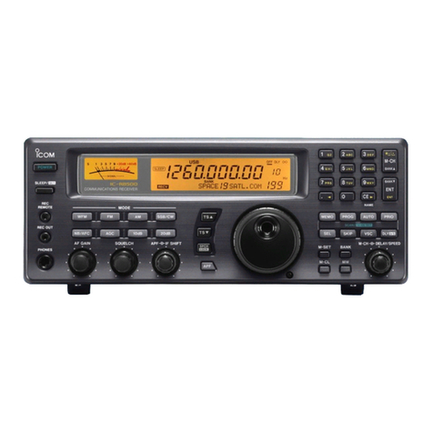
Icom IC-R1500 User manual

INSTRUCTION MANUAL
New2001
iR1500
COMMUNICATIONS RECEIVER
This device complies with Part 15 of the FCC rules. Operation is sub-
ject to the following two conditions: (1) This device may not cause
harmful interference, and (2) this device must accept any interference
received, including interference that may cause undesired operation.
! IC-R1500.qxd 05.10.21 10:07 AM Page A (1,1)

i
New2001
FOREWORD
Thank you for purchasing this Icom product. The IC-R1500
COMMUNICATIONS RECEIVER
is designed and built with Icom’s
state of the art technology and craftsmanship. With proper care,
this product should provide you with years of trouble-free oper-
ation.
We want to take a couple of moments of your time to thank
you for making your IC-R1500 your radio of choice, and hope
you agree with Icom’s philosophy of “technology first.” Many
hours of research and development went into the design of
your IC-R1500.
DD
FEATURES
❍Wide frequency coverage with all mode re-
ceive
❍Real-time bandscope function
❍IF shift function function
❍
ANF and NR functions available (Only when
the DSP unit is installed.)
IMPORTANT
READ ALL INSTRUCTIONS carefully and completely
before using the receiver.
SAVE THIS INSTRUCTION MANUAL— This in-
struction manual contains important operating instructions for
the IC-R1500.
EXPLICIT DEFINITIONS
WORD DEFINITION
RWARNING!
CAUTION
NOTE
Personal injury, fire hazard or electric shock
may occur.
Equipment damage may occur.
Recommended for optimum use. No risk of
personal injury, fire or electric shock.
Icom, Icom Inc. and the logo are registered trademarks of Icom Incor-
porated (Japan) in the United States, the United Kingdom, Germany, France,
Spain, Russia and/or other countries.
! IC-R1500.qxd 05.10.21 10:07 AM Page i (1,1)

ii
New2001
RWARNING RF EXPOSURE! This device emits Radio
Frequency (RF) energy. Extreme caution should be observed when
operating this device. If you have any questions regarding RF expo-
sure and safety standards please refer to the Federal Communica-
tions Commission Office of Engineering and Technology’s report on
Evaluating Compliance with FCC Guidelines for Human Radio fre-
quency Electromagnetic Fields (OET Bulletin 65).
RWARNING! NEVER connect the receiver to an AC outlet.
This may pose a fire hazard or result in an electric shock.
RWARNING! NEVER operate the receiver while driving a
vehicle. Safe driving requires your full attention—anything less may
result in an accident.
NEVER connect the receiver to a power source of more than 16 V
DC. This will damage the receiver.
NEVER connect the receiver to a power source using reverse po-
larity. This will damage the receiver.
NEVER cut the DC power cable between the DC plug and fuse
holder. If an incorrect connection is made after cutting, the receiver
may be damaged.
NEVER expose the receiver to rain, snow or any liquids. The re-
ceiver may be damaged.
NEVER operate or touch the receiver with wet hands. This may
result in an electric shock or damage the receiver.
NEVER place the receiver where normal operation of the vehicle
may be hindered or where it could cause bodily injury.
NEVER let objects impede the operation of the cooling fan on the
rear panel.
AVOID using or placing the receiver in direct sunlight or in areas
with temperatures below –10°C (+14°F) or above +60°C (+140°F).
BE CAREFUL! The receiver will become hot when operating it
continuously for long periods.
AVOID setting the receiver in a place without adequate ventilation.
Heat dissipation may be affected, and the receiver may be damaged.
AVOID the use of chemical agents such as benzine or alcohol
when cleaning, as they can damage the receiver’s surfaces.
USE Icom microphones only (supplied or optional). Other manu-
facturer’s microphones have different pin assignments and may dam-
age the receiver if attached.
For U.S.A. only
CAUTION: Changes or modifications to this device, not ex-
pressly approved by Icom Inc., could void your authority to
operate this device under FCC regulations.
PRECAUTION
! IC-R1500.qxd 05.10.21 10:07 AM Page ii (1,1)

iii
New2001
TABLE OF CONTENTSSUPPLIED ACCESSORIES
qAntenna ………………………………………………………1
wAC adapter …………………………………………………1
eUSB cable …………………………………………………1
rCD ……………………………………………………………1
tLeg pad ………………………………………………………1
FOREWORD ........................................................................................... i
IMPORTANT ............................................................................................ i
EXPLICIT DEFINITIONS ......................................................................... i
PRECAUTION ........................................................................................ ii
SUPPLIED ACCESSORIES .................................................................. iii
TABLE OF CONTENTS ......................................................................... iii
QUICK REFERENCE GUIDE ............................................................. I–X
■Installation ....................................................................................... I
■Your first contact .......................................................................... VII
■Repeater operation ....................................................................... IX
■Programming memory channels..................................................... X
1 PANEL DESCRIPTION ................................................................. 1–5
■Front panel— controller ................................................................. 1
■Function display ............................................................................. 3
■Rear panel ..................................................................................... 5
2 SETTING A FREQUENCY ............................................................ 6–8
■Turning power ON/OFF ................................................................. 6
■Mode selection ............................................................................... 6
■Tuning step selection ..................................................................... 7
■Setting a frequency ........................................................................ 7
■Receive mode selection ................................................................. 8
■Lock function .................................................................................. 8
3 BASIC OPERATION ................................................................... 9–11
■Receiving ....................................................................................... 9
■Monitor function ............................................................................. 9
■Squelch attenuator ....................................................................... 10
■AFC function ................................................................................ 10
■NB function ................................................................................... 11
■AGC function ................................................................................ 11
■VSC function ................................................................................ 11
! IC-R1500.qxd 05.10.21 10:07 AM Page iii (1,1)

iv
New2001
4 MEMORY OPERATION ............................................................ 12–19
■General description ...................................................................... 12
■Memory channel selection ........................................................... 12
■Programming a memory channel ................................................. 13
■Programming channel names ..................................................... 14
■Copying memory contents ........................................................... 16
■Memory clearing .......................................................................... 17
■Memory bank selection ................................................................ 18
■Memory bank setting .................................................................... 18
■Transferring bank contents .......................................................... 19
5 SCAN OPERATION .................................................................. 20–24
■Scan types ................................................................................... 20
■Scan start/stop ............................................................................. 21
■Scan edges programming ............................................................ 22
■Skip channel/frequency setting .................................................... 23
■Scan resume condition ................................................................ 24
6 PRIORITY WATCH .......................................................................... 25
■Priority watch types ...................................................................... 25
■Priority watch operation ............................................................... 25
7 POCKET BEEP AND TONE SQUELCH ................................... 26–28
■Pocket beep operation ................................................................. 26
■Tone/DTCS squelch operation ..................................................... 27
■Tone scan ..................................................................................... 28
8 SET MODE ................................................................................ 29–35
■General ........................................................................................ 29
■Set mode items ............................................................................ 29
9 SPECIFICATIONS AND OPTIONS ........................................... 37–39
■Specifications ............................................................................... 37
■Options ......................................................................................... 39
■AM/FM narrow mode ................................................................... 65
■Weather channel operation (USA version only) ........................... 66
■Microphone keys .......................................................................... 67
■Partial reset .................................................................................. 68
■All reset ........................................................................................ 68
■Data cloning ................................................................................. 69
■Packet operation .......................................................................... 71
12 MAINTENANCE ........................................................................ 75–76
■Troubleshooting ........................................................................... 75
■Fuse replacement ........................................................................ 76
9 SPECIFICATIONS AND OPTIONS ........................................... 37–39
■Specifications ............................................................................... 37
■Options ......................................................................................... 39
14 MODE ARRANGEMENT ........................................................... 79–80
! IC-R1500.qxd 05.10.21 10:07 AM Page iv (1,1)
1
PANEL DESCRIPTION
New2001
1
■Front panel— controller
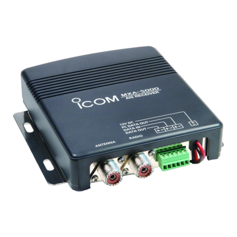
qSET•LOCK SWITCH [SET•LOCK]
➥Enters set mode when pushed. (p. ??)
➥Switches the lock function ON and OFF when pushed
for 1 sec. (p. ??)
wTUNING STEP/MODE [TS•MODE]
➥Push to select the tuning step. (p. ??)
➥Each push for 1 sec. selects the operating mode. (p. ??)
eVOLUME CONTROL [VOL] (p. ??)
Adjusts the audio level.
rPOWER SWITCH FOR CONTROLLER [PWR]
Turns the controller power ON and OFF when pushed for
1 sec.
tSQUELCH CONTROL [SQL]
Varies the squelch level. (p. ??)
yMONITOR•TONE•TONE SCAN SWITCH
[MONI•T/T-SCAN]
➥Push to switch the monitor function ON and OFF. (p. ??)
➥Push for 1 sec. to enter the tone function selection
mode. (pgs. ??, ??)
• Subaudible tone encoder, pocket beep (CTCSS), tone
squelch, pocket beep (DTCS), DTCS squelch or tone func-
tion OFF can be selected.
➥Push for 1 sec. during tone function selection mode to
start the tone scan. (p. ??)
S
E
T
L
O
C
K
S
.
M
W
M
W
rewq
!2 !1 !0 oi uy t
Function display (☞p. ??)
! IC-R1500.qxd 05.10.21 10:07 AM Page 1 (1,1)

2
11
PANEL DESCRIPTION
New2001
1
2
3
4
5
6
7
8
9
10
11
12
13
14
15
16
uNOISE BLANKER/AUTOMATIC GAIN CONTROL
SWITCH [NB•AGC]
➥Push to switch the NB (Noise Blanker) function ON and
OFF. (p. ??)
• The noise blanker function cannot be used in WFM mode.
➥Push for 1 sec. to switch the AGC (Automatic Gain Con-
trol) function ON and OFF. (p. ??)
iATTENUATOR/PRIORITY SWITCH [ATT•PRIO]
➥Push to switch the ATT (Attenuator) function ON and
OFF. (p. ??)
➥Starts priority watch when pushed for 1 sec. (p. ??)
oMEMORY/SKIP SWITCH [MR•SKIP]
➥Push to select and toggle memory and weather chan-
nel* modes. (pgs. ??, ??, ??)
*Weather channels are available for USA version only.
➥Push for 1 sec. to turn the channel skip setting ON and
OFF for memory skip scan operation. (p. ??)
!0 VFO/MHz TUNING•SCAN SWITCH [V/MHz•SCAN]
➥Selects and toggles VFO mode and 1 MHz (or 10 MHz
for some versions) tuning when pushed. (p. ??)
➥Starts scan when pushed for 1 sec. (p. ??)
• Cancels a scan when pushed during scan.
!1 TUNING DIAL [DIAL]
Selects the operating frequency (p. ??), memory channel
(p. ??), the setting of the set mode item and the scanning
direction (p. ??).
!2 MEMORY WRITE SWITCH [S.MW•MW] (pgs. ??, ??, ??)
➥Selects a memory channel for programming when
pushed.
➥Programs the selected memory channel when pushed
for 1 sec.
!3 POWER SWITCH FOR RECEIVER [POWER]
Turns the receiver power ON and OFF
! IC-R1500.qxd 05.10.21 10:07 AM Page 2 (1,1)

3
1PANEL DESCRIPTION
New2001
■Function display
qAFC INDICATOR
Appears when the AFC function is in use. (p. ??)
wFM CENTER INDICATORS (p. ??)
➥“ ” or “ ” appears when the received signal is not
tuned to its center frequency; or the squelch is closed.
➥“ ” appears when the received signal is tuned to its
center frequency.
eRECEIVE MODE INDICATORS
Shows the selected receive mode.
• LSB, USB, CW, AM, FM and WFM are available.
rAGC INDICATOR (p. ??)
Appears when the AGC function in use. (p. ??)
tNB INDICATOR (p. ??)
Appears when the NB function is in use. (p. ??)
yDSP INDICATOR (p. ??)
Appears when the DSP digital filter function is in use.
e r t yq w
!7 !6 !5 !4 !3
o
!0
u
!8
!2 !1
i
!9
! IC-R1500.qxd 05.10.21 10:07 AM Page 3 (1,1)

4
1
PANEL DESCRIPTION
New2001
1
2
3
4
5
6
7
8
9
10
11
12
13
14
15
16
uFREQUENCY READOUT
Shows the operating frequency, channel names, set mode
contents, etc.
• Frequency decimal point blinks while scanning. (p. ??)
• “d” appears in place of the 1st digit while the DTMF memory
function is in use. (p. ??)
iMEMORY INDICATOR (pgs. ??, ??)
Appears when memory mode is selected.
oAUTO POWER-OFF INDICATOR (p. ??)
Appears while the auto power OFF function is in use.
!0PRIORITY INDICATOR (p. ??)
Appears while the priority watch is activated; blinks while
the watch is paused.
!1MEMORY CHANNEL NUMBER INDICATORS
➥Shows the selected memory channel number. (p. ??)
➥Shows the selected bank initial. (p. ??)
➥“L” appears when the lock function is activated. (p. ??)
!2SKIP INDICATORS (p. ??)
➥“~” appears when the displayed memory channel is
specified as a skip channel.
➥“P ~” appears when the displayed frequency is spec-
ified as a program skip frequency.
!3VSC INDICATOR (p. ??)
Appears when the VSC function is in use. (p. ??)
!4TONE SQUELCH INDICATOR (p. ??)
Appears when the tone squelch function is in use. (p. ??)
!5POKET BEEP INDICATOR (p. ??)
➥Appears when the poket beep function is in use. (p. ??)
➥Appears with “ ” or “ ” while the pocket beep func-
tion (with CTCSS or DTCS) is in use. (p. ??)
!6DTCS SQUELCH INDICATOR (p. ??)
Appears while the DTCS squelch function is in use. (p. ??)
!7ATT INDICATOR (p. ??)
Appears when the ATT function is in use. (p. ??)
!8BUSY INDICATOR
➥Appears when a signal is being received or the squelch
is open. (p. ??)
➥Blinks while the monitor function is in use. (p. ??)
!9S-METER INDICATORS
Shows the relative signal strength while receiving signals.
(p. ??)
! IC-R1500.qxd 05.10.21 10:07 AM Page 4 (1,1)

5
1PANEL DESCRIPTION
New2001
■Rear Panel
qANTENNA CONNECTOR [ANT]
Connects a 50 Ωantenna with a BNC connector and a 50
Ωcoaxial cable.
wEXTERNAL SPEAKER JACK [EXT SP]
Connects an 8 Ωexternal speaker.
• Audio output power is more than 0.5 W.
eUSB RECEPTACLE [USB]
Connects to a PC via an extension cable.
rCONTROLLER [CONTROLLER]
Connects to a controller via an extension cable.
tDATA SOCKET [PACKET]
Connects a TNC (Terminal Node Controller), etc. for data
communications. The receiver can receive 9600 bps
packet communication (AFSK.)
• See p. ? for connection information.
yPOWER RECEPTACLE [DC IN]
Accepts 12 V DC ±15% with the supplied DC power cable.
☞NOTE: DO NOT use a cigarette lighter socket as a
power source when operating in a vehicle. The plug
may cause voltage drops and ignition noise may be su-
perimposed onto receive audio.
uGROUND TERMIAL [GND]
Connect this terminal to a ground.
q
uy t r ew
! IC-R1500.qxd 05.10.21 10:07 AM Page 5 (1,1)

6
2
SETTING A FREQUENCY
1
2
3
4
5
6
7
8
9
10
11
12
13
14
15
16
■Turning power ON/OFF
➥Push [PWR] for 1 sec. to turn power ON and OFF.
■Mode selection
DVFO modes
VFO mode is used for the desired frequency setting within the
frequency coverage.
➥Push [V/MHz•SCAN] to select VFO mode.
What is VFO?
VFO is an abbreviation of Variable Frequency Oscillator. Fre-
quencies for receiving are generated and controlled by the
VFO.
DMemory mode/Weather channels*
Memory mode is used for operation of memory channels
which have programmed frequencies. Weather channels* are
monitored each 5 sec. when the weather alert function is
turned ON.
*Available for the USA version only.
qPush [MR•SKIP] several times to select the channel type.
• Memory mode/Weather channels can be selected in sequence.
•“!” indicator appears when memory mode is selected.
wRotate [DIAL] to select the desired channel.
• Only programmed memory channels can be selected.
• See p. ?? for memory programming details.
[DIAL]
[MR•SKIP]
[V/MHz•SCAN]
[PWR]
! IC-R1500.qxd 05.10.21 10:07 AM Page 6 (1,1)

7
2SETTING A FREQUENCY
New2001
■Tuning step selection
When using the tuning dial to change the frequency, or when
a scan function is activated, the frequency changes in incre-
ments determined by the set tuning step. This can be
changed if desired.
The following tuning step are available.
• 1 Hz • 10Hz • 20 Hz • 50 Hz • 100 Hz
• 500Hz • 1 kHz • 2.5 kHz • 5 kHz • 6.25 kHz
• 8.33 kHz • 9 kHz • 10 kHz • 12.5 kHz • 15 kHz
• 20 kHz • 25 kHz • 30 kHz • 50 kHz • 100 kHz
• 125 kHz • 150 kHz • 200 kHz • 500 kHz • 1 MHz
• 10 MHz
qPush [V/MHz•SCAN] to select VFO mode, if necessary.
wPush [TS•MODE] to enter the tuning step select mode.
rRotate [DIAL] to select the desired tuning step.
tPush [TS•MODE] to exit the tuning step select mode.
■Setting a frequency
qRotate [DIAL] to set the frequency.
• If VFO mode is not selected, push [V/MHz•SCAN] to select VFO
mode.
• The frequency changes in the selected tuning steps. (p. ??)
wTo change the frequency in 1 MHz (10 MHz for some ver-
sions) steps, push [V/MHz•SCAN], then rotate [DIAL].
• Pushing [V/MHz•SCAN] for 1 sec. starts scan function. If scan
starts, push [V/MHz•SCAN] again to cancel it.
While 1 MHz tuning step is
selected, the digit below
100 kHz disappear.
While 10 MHz tuning step is
selected, the digit below 1
MHz disappear.
[DIAL]
[V/MHz•SCAN]
[DIAL]
[TS•MODE]
[V/MHz•SCAN]
! IC-R1500.qxd 05.10.21 10:07 AM Page 7 (1,1)

8
2
SETTING A FREQUENCY
New2001
1
2
3
4
5
6
7
8
9
10
11
12
13
14
15
16
■Receive mode selection
Receive modes are determined by the physical properties of
the radio signals. The receiver has 6 receive modes: SSB
LSB, CW, AM, WFM and FM modes. The mode selection is
stored independently in each memory channels.
Typically, AM mode is used for the AM broadcast stations
(0.495–1.620 MHz) and air band (118–135.995 MHz), and
WFM is used for FM broadcast stations (76–107.9 MHz).
When Automatic mode is selected, IF filter passband width,
tuning step, etc., are selected automatically after inputting a
frequency. (p. ??)
➥Push [TS•MODE] for 1 sec. to enter the receive mode se-
lect mode.
rRotate [DIAL] to select the desired mode.
tPush [TS•MODE] to exit the receive mode select mode.
■Lock function
To prevent accidental frequency changes and unnecessary
function access, use the lock function.
➥Push [SET•LOCK] for 1 sec. to turn the lock function ON
and OFF.
•[SET•LOCK] (lock function only), [MONI•T/T•SCAN] (monitor
function only), [PWR], [VOL] and [SQL] can be used while the
channel lock function is in use.
[SET•LOCK]
[DIAL]
[TS•MODE]
! IC-R1500.qxd 05.10.21 10:07 AM Page 8 (1,1)

9
BASIC OPERATION
New2001New2001
3
■Receiving
qPush [PWR] for 1 sec. to turn power ON.
wSet the audio level.
➥Push [MONI•T/T-SCAN] to open the squelch.
➥Rotate [VOL] to adjust the audio level.
➥Push [MONI•T/T-SCAN] to close the squelch.
eSet the squelch level.
➥Rotate [SQL] fully counterclockwise in advance, then
rotate [SQL] clockwise until the noise just disappears.
• When interference is received, rotate [SQL] clockwise again
for attenuator operation. (p. ??)
rSet the receive frequency. (pgs. ??, ??)
tWhen receiving a signal on the set frequency, squelch
opens and the receiver emits audio.
• “BUSY” appears and the S-meter indicator shows the relative
signal strength for the received signal.
■Monitor function
This function is used to listen to weak signals without disturb-
ing the squelch setting or to open the squelch manually even
when mute functions such as the tone squelch are in use.
➥Push [MONI•T/T-SCAN] to open the squelch.
• “BUSY” blinks.
• Push [MONI•T/T-SCAN] again to cancel the function.
[MONI•T/T-SCAN]
[PWR]
[VOL]
[SQL]
[MONI•T/T-SCAN]
! IC-R1500.qxd 05.10.21 10:07 AM Page 9 (1,1)

10
3
BASIC OPERATION
1
2
3
4
5
6
7
8
9
10
11
12
13
14
15
16
New2001
■Squelch attenuator
The attenuator prevents a desired signal from distorting when
very strong signals are near the desired frequency or when
very strong electric fields, such as from a broadcasting sta-
tion, are near your location. The attenuator gain is about 20
dB.
➥Push [ATT•PRIO] to toggle the attenuator function ON and
OFF.
• “ATT” appears when the attenuator function is in use.
■AFC function [
The AFC (Automatic Frequency Control) function tunes the
displayed frequency automatically when an off-center fre-
quency is received. It activates in FM/WFM modes only.
qSelect FM mode.
wPush [SET•LOCK] to enter set mode.
ePush [SET•LOCK] or [S.MW•MW] several times until
“AFC” appears.
rRotate [DIAL] to toggle the AFC function ON and OFF.
tPush [TS•MODE] to exit set mode.
• “AFC” appears when the AFC function is in use.
[TS•MODE]
[DIAL]
[S.MW•MW]
[SET•LOCK]
[ATT•PRIO]
! IC-R1500.qxd 05.10.21 10:07 AM Page 10 (1,1)

11
3BASIC OPERATION
New2001
■NB function
The NB (noise blanker) function removes pulse-type noise
when USB, LSB or CW mode is selected.
➥Push [NB•AGC] to toggle the NB function ON and OFF.
• “NB” appears when the NB function is in use.
■AGC function
The AGC (Automatic Gain Control) function controls receiver
gain to produce a constant audio output level even when the
received signal strength is varied by fading, etc.
➥Push [NB•AGC] for 1 sec. to toggle the AGC function ON
and OFF.
• “AGC” appears when the AGC function is in use.
■VSC function [
The VSC (Voice Squelch Control) function opens the squelch
only when receiving a modulated signal. This function is very
useful while scanning, the VSC pauses only when modulated
signals are received. Scanning continues when unmodulated
or beat signals are received.
qPush [SET•LOCK] to enter set mode.
wPush [SET•LOCK] or [S.MW•MW] several times until
“VSC” appears.
eRotate [DIAL] to toggle the VSC function ON and OFF.
rPush [TS•MODE] to exit set mode.
• “VSC” appears when the VSC function is in use.
[TS•MODE]
[DIAL]
[S.MW•MW]
[SET•LOCK]
[NB•AGC]
[NB•AGC]
! IC-R1500.qxd 05.10.21 10:07 AM Page 11 (1,1)

12
4
MEMORY OPERATION
1
2
3
4
5
6
7
8
9
10
11
12
13
14
15
16
■General description
The receiver has 1050 memory channels including 50 scan
edge memory channels (25 pairs) for storage of often-used
frequencies. And a total of 26 memory banks, A to Z are avail-
able for usage by group, etc. Up to 100 channels can be as-
signed into a bank.
DDMemory channel contents
The following information can be programmed into memory
channels:
• Operating frequency (p. ??)
• Receive mode (p. ??)
• Tone squelch or DTCS squelch ON/OFF (p. ??)
• Tone squelch frequency or DTCS code with polarity
(p. ??)
• Scan skip information (p. ??)
■Memory channel selection
qPush [MR•SKIP] several times to select memory mode.
•“!” indicator appears.
wRotate [DIAL] to select the desired memory channel.
• Programmed memory channels only can be selected.
! IC-R1500.qxd 05.10.21 10:07 AM Page 12 (1,1)

13
4MEMORY OPERATION
New2001
VFO settings, including the set mode contents such as sub-
audible tone frequency or scan skip information, can be pro-
grammed into a memory channel.
qPush [V/MHz•SCAN] to select VFO mode.
wSet the desired frequency using [DIAL].
➥Set other data (e.g. subaudible tone frequency, scan
skip information, etc.) if required.
ePush [S.MW•MW] to select the select memory write con-
dition.
•“!” indicator and the memory channel number blink.
rRotate [DIAL] to select the desired memory channel to be
programmed.
• Memory channels not yet programmed are blank.
tPush [S.MW•MW] for 1 sec. to program.
• 3 beeps sound
• Memory channel number automatically increases when contin-
uing to push [S.MW•MW] after programming.
✔CONVENIENT
Memory programming can be performed in versatile ways
e.g. memory channel to the same (or different) memory chan-
nel, etc.
■Programming a memory channel
! IC-R1500.qxd 05.10.21 10:07 AM Page 13 (1,1)

14
4
MEMORY OPERATION
New2001
1
2
3
4
5
6
7
8
9
10
11
12
13
14
15
16
■Programming channel names
Each memory channel can be programmed with an alphanu-
meric channel name for easy recognition and can be indi-
cated independently by channel. Names can be a maximum
of 8 characters— see the table below for available charac-
ters.
qSelect the desired memory channel.
➥Push [MR•SKIP] several times to select memory mode,
then rotate [DIAL] to select the desired memory channel.
•“!” and memory channel number blink.
ePush [S.MW•MW] to select the memory name program-
ming condition.
• Frequency readouts disappear and a cursor blinks.
rRotate [DIAL] to select the desired character.
• The selected character blinks.
tPush [SET•LOCK] to move the cursor to the right.
yRepeat steps rand tuntil the desired channel names
are displayed.
uPush [S.MW•MW] for 1 sec. to program the name and exit
the channel name programming condition.
(1)
(B)
(L)
(V)
(+)
(2)
(C)
(
M
)
(
W
)
(–)
(3)
(
D
)
(N)
(X)
(=)
(4)
(E)
(O)
(Y)
(✱)
(5)
(F)
(P)
(Z)
(/)
(6)
(G)
(
Q
)
(space)
(7)
(()
(
H
)
(
R
)
())
(8)
(I)
(S)
(|)
(9)
(J)
(T)
(0)
(A)
(
K
)
(U)
! IC-R1500.qxd 05.10.21 10:07 AM Page 14 (1,1)

15
4MEMORY OPERATION
New2001
DDTo indicate the channel name [
The channel name indication can be set for independent
memory channels.
qSelect the desired memory channel.
➥Push [MR•SKIP] several times to select memory mode,
then rotate [DIAL] to select the desired memory channel.
•“!” and memory channel number blink.
ePush [SET•LOCK] to enter set mode.
rPush [SET•LOCK] or [S.MW•MW] several times to select
“ANM” item.
tRotate [DIAL] to turn the memory name indication ON.
yPush [TS•MODE] to exit set mode.
NOTE: When no memory name is programmed, the stored
frequency is displayed.
! IC-R1500.qxd 05.10.21 10:07 AM Page 15 (1,1)
Other manuals for IC-R1500
1
Table of contents
Other Icom Receiver manuals