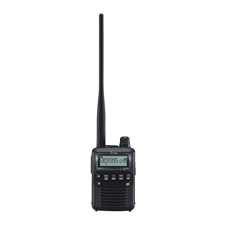
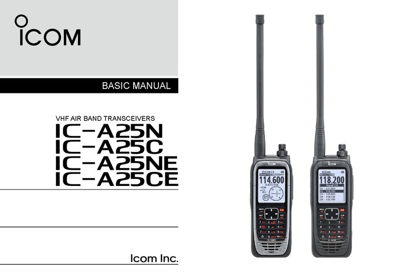
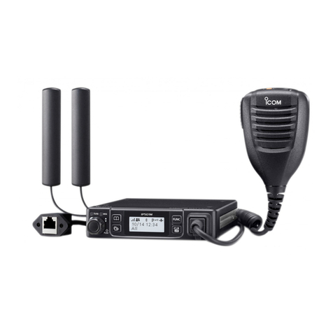
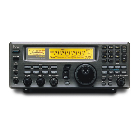
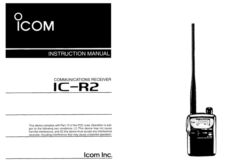
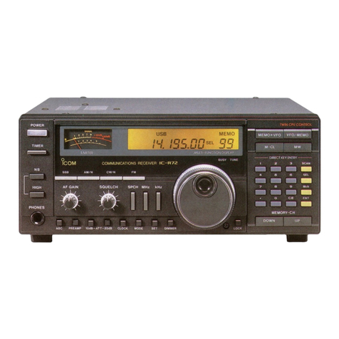
Icom IC-R1 User manual

IC-Rl
WIDEBAND RECEIVER

IMPORTANT
READ ALL INSTRUCTIONS carefully and
completely before using the IC-R1.
SAVE THIS INSTRUCTION MANUAL -
This instruction manual contains important safety and oper-
ating instructions for the IC-R1.
The use of non-lcom battery packs/chargers may impair
transceiver performance and invalidatethe warranty.
OPERATING NOTES
Information overheard through the IC-R1, but not intended
for you, cannot be lawfully used in any way.
The IC-R1 may receive its own oscillated frequency, result-
ing in no reception or only noise reception, on some fre-
quencies.
The IC-R1 may receive interference from extremely strong
signals on different frequencies or when using an external
high-gain antenna.
CAUTIONS
NEVER connect a non-recommended charger. This
may result in a fire hazard or an electric shock.
NEVER connect more than a 16 V DC power source to
the receiver. This will ruin the receiver.
DO NOT use or place the receiver in areas with temper-
atures below -10°C (+ 14"F) or over +60°C (+140"F).
AVOID the use of strong chemical agents such as
benzine or alcohol when cleaning, as they may damage the
receiver surfaces.
EXPLICIT DEFINITIONS
The following explicit definitions apply to this manual:
•••Y:WORD •••••••••••••••••••••••••••••••••••••••••••••
bEFINl::rioN •••••••••••••••.•••••••..........
CAUTION Equipment damage and/or personal in-
jury could occur.
If disregarded, inconvenience only. No
NOTE risk of personal injury or equipment
damage.
Push [xl
+
[yl While pushing switch 'x', push switch 'y.'
Downloaded
by
RadioManuai.EU

• Memory scan watch ·40
TABLE OF CONTENTS
IMPORTANT· I
OPERATING NOTES· I
CAUTIONS, I
EXPLICIT DEFINITIONS I
TABLE OF CONTENTS· ·11
FOREWORD
·······················1
UNPACKING·
·1
1
PRE-OPERATION ·.. ·.. 2
2 PANEL DESCRIPTION·
3-8
• Front and side panels' ·3
.Top panel .. ···· .. · ··········4
• Keyboard 5
• Function display··············· ···7
3 BATTERY CHARGING······
'9-10
4 ACCESSORY ATTACHMENT··
11
5
BASIC OPERATION
12-20
• General· ·12
• Selecting VFO mode 12
• Selecting a receive mode 13
• Selecting a tuning step' 14
.Tuning a frequency
(via the keyboard) 15
.Tuning a frequency
(via the tuning control) 16
• Dial select steps' 17
• Lock function 17
• Listening example 1 '18
• Listening example 2 , ,19
6
MEMORY MODE·
21-24
.General·,·, ·, .. · · .. 21
• Selecting MEMORY mode· ·21
• Selecting a memory channel· , ·22
• Programming a memory channel' ·23
• Transferring a memory to VFO . , , ·24
• Masking a memory channel .... ,. 24
7
SCAN OPERATION, . , ,
25-37
• What is scanning? , ·25
• Scan types .•...... , ·25
• Programmed scan' . , , .. , ·27
• Programming scan edges ·29
• Programming skip scan , . , . ·31
• Setting and cancelling skip
information ' , , , ·32
• Auto-memory write scan 33
• Memory scan ·34
• Memory select scan ··,··········35
• Mode select scan ·,·,···········36
• Summary of scan types ' , ·37
8
PRIORITY WATCH·,
····38-40
• What is priority watch? ·38
• Types of priority watch 38
• Memory channel watch,········ ·39
9 CLOCK MODE
41-44
• What is CLOCK mode? " ·41
• Setting the time , , ·41
• Power-on timer , ·43
• Sleep timer' , ·44
10
OTHER FEATURES,
45-46
• Display contrast· , ,45
• Monitor function' '45
• Display lighting······,·,········ ·45
• Battery indicator' , , ·46
• Beep tones' , '46
• Power saver' ·46
11
SET MODE
47-50
.General· ,···,·· .. ",
'''47
• Entering SET mode , ·48
• Setting displays' , ·48
12
TROUBLESHOOTING
51-53
• Troubleshooting ., ·51
• Exiting a display' , ·53
13
SPECIFICATIONS
·········54
14
OPTIONS 55
ii
Downloaded
by
RadioManuai.EU
FOREWORD
Thank -you for purchasing the IC-R1 WIDEBAND
RECEIVER, a state-of-the-art handheld receiver made
with Icom's most advanced technology.
The IC-R1 has the following features:
• Incredibly compact size and weight including the inter-
nal NiCd battery .
• Wideband frequency coverage
0.1-1300 MHz"· .• in AM, FM and Wide FM modes .
•, Guaranteed range: 2-905 MHz. Some versions do not have
the full range because of frequency restrictions .
.• MHz is an abbreviation of megahertz or 1.000.000 hertz.
where hertz is a unit of frequency.
INFO
Electromagnetic radiation which has frequencies of 20,000
Hz (20 kHz) and above is called radio frequency (RF)
energy because it is useful in radio transmissions. The
IC-R1 receives RF energy and converts it into audio fre-
quency (AF) energy which in turn actuates a loudspeaker to
create sound waves. AF energy is in the range of
20-20,000 Hz.
Qty.
UNPACKING
Accessories included with the IC-R1:
CD
Handstrap... 1
®
Antenna (FA-4B)........................................................ 1
@Wall charger 1
@
Belt clip and screws............................................ 1 set
Q
Downloaded
by
RadioManuai.EU

1 Charge .the battery.
Connect the supplied wall charger
as illustrated in the diagram be-
low.
• The CPU backup battery will also be
fully charged.
• See p. 9 for details on safety and
use of a desktop charger.
• NEVER attempt to charge a
battery case containing dry cell
(i.e. non-rechargeable) batter-
ies.
PRE-OPERATION
2 Reset the receiver.
When first applying power, the internal recharge-
able backup battery may be empty. In this case,
before you can operate the receiver, the following
reset procedure must be performed. While push-
ing [F] and [Cl.] , rotate [PWRNOll to turn power
ON.
_-"-="I-I---[PWRNO
L]
• The display returns to its factory-shipped default
settings. (see p. 51)
CAUTION: Resetting the CPU will clear and
initialize all memory channel contents, pro-
grammed scan edge frequency bands, SET mode
settings and clock and timer settings.
3 Connect the
antenna.
Insert the supplied antenna
into the antenna connector
and rotate the antenna as
shown in the diagram below.
Do not remove the attached
rubber cap as it helps pre-
vent dust from entering the
receiver.
W
J
s->
0
111 1 1
2
Downloaded
by
RadioManuai.EU
PANEL DESCRIPTION
• Front and side panels
WATCH SWITCH [W]
Used to activate CLOCK mode. (see
p.41)
FUNCTION SWITCH [F)
While pushing [F), the secondary func-
tions of switches and controls can be
accessed. (see pgs. 5, 6)
CONTRAST SWITCH [CONT]
Adjusts the function display contrast.
(see p. 45)
MONITOR SWITCH [MONI]
Opens the squelch fully for reception
of weak signals under certain condi-
tions. (see pgs. 12, 45)
BATTERY PACK RELEASE BUTTON
Opens the latch for bottom cap or
optional battery cap removal. (see p.
11)
3
RECEIVE INDICATOR [RX]
Lights up in green while receiving.
Indicates that the squelch needs ad-
justment if it lights while receiving no
signal. (see p. 12)
FUNCTION DISPLAY
Indicates the operating condition. (see
pgs. 7, 8)
LIGHT SWITCH [LIGHT]
Used to backlight the function display.
Lights the display for approximately 5
sec. except when the light function is
activated. (see p. 45)
SPEAKER
Emits the receive audio.
KEYBOARD
Numeral and other function keys for
tuning and activating functions. (see
pgs. 5, 6)
Downloaded
by
RadioManuai.EU

• Top panel
EXTERNAL DC POWER JACK
[DC
13.8
V]
Connects the supplied wall charger for
charging the internal batteries or at-
tached battery pack. (see p.
9)
.
::;,:::::::::::::::::::::::::.::::::.:
..
::::
..
::
..
:::':.:;:'.:.:::.::
..
::::::.:
...
::::::::::::::::::::::':.,
...
·.~~·p~r~fHI§fq'l~rgh~rgl~gl••••••••••••••••••••••••••••••
••pp~r(:lti9~··WithElr extE3rr1al.·bd.·p()wer
··sClyrc:~sim~lt~r1~9y~IYsfl~rge~tfl~.b.at~ ••·
tel')'p~ck.·
ANTENNA CONNECTOR
Connects the supplied flexible antenna.
Be careful when connecting an exter-
nal antenna. (see p. 2 and OPER-
ATING NOTES on p, i)
SQUELCH CONTROL [SQUELCH]
Varies the squelch threshold point for
audio mute. (see p.
12)
• Pushing [MONI] opens the squelch fully.
PANEL DESCRIPTION
1
EXTERNAL SPEAKER JACK [SP]
Connects an 8 Q optional speaker or
earphone, if desired.
• The internal speaker will not function
when either option is connected .
LINE OUT JACK [LINE OUT]
~~~~~1r~~~
Use a submini plug to connect to a
~ ((~~~---I
tape recorder in order to record the
signal being received.
• Use the volume control to adjust the re-
cording level.
TUNING CONTROL
Used to set an operating frequency
(see p. 16) or a memory channel (see
p.22).
VOLUME CONTROL [PWRNOL]
Turns power ON and adusts the audio
level. (see p.
12)
4
Downloaded
by
RadioManuai.EU
I
I
1PANEL DESCRIPTION
MODE
G)
T.S
G)
SKIP
CD
APON
CD
SLEEP
G)
MASK
G:)
PRIO
CD
SET
G)
DIAL-SEL
G)
MODE-S
CD
5
• When selecting VFO mode: In MEMORY mode: turns the memory mask function ON and OFF. (see p.
enter a digit for the receive 24)
frequency. (see p. 15) i-S-t-a-rts-/-st-o-p-s-p-ri-or-ity-w-a-t-ch-.-(-Se-e-p-g-s-.-3-9-,-40-)------------i
r-M:O~DE~~T=.S:_~S~K~IP M.V
(0 CD CD)
~»
AP ON SLEEP MASK MW
~;::::C :=)~CI:=5~)
-(-=: :5j)
«~»
.-;;P~R~IO'-_:::S~ET~-"D~IA~L;;;;;SELP-SET
(CD
CD CD)
(0)
SEL·M MODE-S AUTO MS P-SCAN
Cb
CD
@)G)
InVFO mode: selects a receive mode, FM, AM or W FM. (see p. 13)
In VFO mode: selects a tuning step. Use together with the tuning control for
selection. (see p. 14) •
In MEMORY mode: designates skip channels for memory scan. (see p. 32)
In CLOCK mode: starts the power-on timer. (see p. 43)
Starts the sleep timer. (see p. 44)
In VFO mode: selects a dial select step. (see p. 17)
In MEMORY mode: starts/stops mode select scan. (see p. 36)
L-
~~--~========~------~~--
Downloaded
by
RadioManuai.EU
In VFO mode: increments or decrements the
memory channel number. (see p. 22)
In MEMORY mode: increments and decrements
memory channels which are NOT masked. (see
t--------i
p. 22)
In SET or CLOCK modes: changes the display
contents. (see pgs. 41. 48)
SEL·M
C )
AUTOMS
~
MW
~
P·SET
G)
P·SCAN
G)
PANEL DESCRIPTION 1
In VFO mode: clears the digits to the right of the In MEMORY mode: starts/stops memory select scan.
decimal point for frequency input. (see p. 35)
(see p. 15)
In VFO mode: enters the selected receive fre- In VFO mode: starts/stops auto-memory write scan.
quency. (see p. 15) (see p. 33 )
In MEMORY mode: enters a selected memory
channel. (see p. 22)
Selects VFO mode when pushed in MEMORY In MEMORY mode: transfers memory contents to VFO
mode. (see p. 13) mode. (see p. 24 )
Stops scanning. (see p. 37)
Clears numeric key input. (see p. 15)
In VFO mode: selects MEMORY mode. (see p.
21)
In MEMORY mode: changes the memory chan-
nel number in increments of 10. (see p. 22)
In VFO mode: writes to a memory channel. (see p. 23)
In VFO mode: activates the condition for setting pro-
grammed scan edge frequencies for programmed scan.
(see p. 29)
In VFO mode: starts/stops programmed scan. (see p. 27)
In MEMORY mode: starts/stops memory scan. (see p, 34)
6
Downloaded
by
RadioManuai.EU

1
PANEL DESCRIPTION
• Function display
FUNCTION INDICATOR
Appears while the function [F] switch is RECEIVE MODE INDICATOR
pushed. (see pgs. 5, 6) Indicates the selected receive mode.
(see p. 13)
.
FREQUENCY READOUT
Shows the receiving frequency or the SET MODE INDICATOR
SET mode contents. (see pgs. 15 and
-.
./
Appears while SET mode is selected.
47)
l
mlw
FM AM 'AUTO SET....
(see p. 48)
I,
00.,.""
O"""5l.A
fLfLfO:OOLf ~
DIAL SELECT INDICATORS
II
1~.~. :'J.fl.lil•.l~ _~
I--
MEMORY CHANNEL INDICATOR
~CAN SKIP PROG PRIO , -'
One of these indicators appears while
TS 0.5 8 9 10 12~15 20 25 30 50
Shows the selected memory channel
pushing [F]. It shows the dial select
=.
number. (see p. 22)
step. (see p. 17)
PROGRAMMED SCAN INDICATOR
S-INDICATOR Appears while selecting a programmed
Shows the relative signal strength while scan edge channel. (see p. 29)
receiving. (see p. 16)
7
Downloaded
by
RadioManuai.EU
LOW BATTERY INDICATOR
Appears when the connected battery
requires charging. (see p. 46)
LOCK INDICATOR
Appears while the lock function is acti-
vated. (see p. 17)
SCAN INDICATOR
Appears while scanning. (see p. 25)
SKIP INDICATOR
Appears when the selected memory
channel is set as a skip channel.
• Blinks while scanning if skip channels
have been designated. (see p. 32)
TUNING STEP INDICATORS
Show the selected tuning step. (see p.
14)
PANEL DESCRIPTION
1
AUTO MEMORY WRITE SCAN
INDICATOR
Blinks while auto-memory write scan is
activated. (see p. 33 )
SCAN UP/DOWN INDICATORS
Blink to indicate scan direction while
scanning. (see p. 28)
MEMORY INDICATOR
Appears while MEMORY mode is se-
lected. (see p. 21)
PRIORITY WATCH INDICATOR
Appears while operating a priority
watch. (see p. 38)
8
Downloaded
by
RadioManuai.EU
1-
3
1-
BATTERY CHARGING
The IC-R1's internal battery is a re-
chargeable NiCd and can typically be
recharged up to 300 times (approx.)
Charge the internal battery when the
low battery indicator, • (;] , appears.
• When using the receiver without an op-
tional attached battery pack or case the
internal battery provides about
2-3
hrs. of
operation (with a continuous signal. such
as a broadcast. at medium audio output) .
• When using the receiver with an optional
battery pack or case, the operating times
vary with the capacity of the pack or
batteries used with the case. When the
attached battery pack or case becomes
exhausted, remove it and continue opera-
tion using the internal battery.
NOTE: When an optional battery pack
is attached, the internal battery cannot
be Charged.
CAUTION: Never attempt to charge a
battery case containing non-
rechargeable batteries.
9
Regular charging of the
internal battery
Connect the supplied wall charger to
the [DC 13.8 V] jack.
IC-R1
Supplied wall
charger
• Charging period: 15 hrs. (approx.)
Rapid charging with the
optional BC-72
The BC-72 allows you to rapidly
charge the internal battery or an
attached optional battery pack.
• To charge the internal battery. the
optional BA-12 BATIERY CHARGE
ADAPTER must be attached.
BC-72
(optional)
IC-R1
with
attached
BA-12
NOTE: NiCd batteries with the
BP-90 BATIERY CASE cannot be
charged using the BC-72 .
• Charging period: 1-2 hrs.(approx.)
Downloaded
by
RadioManuai.EU
Charging with an op-
tional charger or cables
BC-73E/D for BP-81 or 82 only
BC-74A/E/DN for BP-81-85, 90
• NEVER connect the above options
when using the BP-90 with dry cell
(l.e. non-rechargeable) batteries.
• Charging period: 15 hrs. (approx.)
CP-12 (optional)
To cigarette
lighter socket
~
white
EB
~
black
e
OPC-254 (optional)
to
[DC 13.8 V]
Charging the optional
BP-85
To charge the optional BP-85 by
itself, connect the wall charger or
optional cable to the charging jack.
BC-74A/E/DN
e..
~~
CP-12 (optional)
OPC-254 (optional)
• The BC-73E/D cannot be used
with the BP-85.
• Charging period: 15 hrs. (approx.)
BATTERY CHARGING
3
• Using your battery wisely
Overcharging and complete discharging
may shorten the life of a battery.
Recharging can usually be performed
300 times, but battery life can be
lengthened to about 500 recharges as
follows:
1. Avoid overcharging. The charging
period should be less than 48 hours.
2. Use the battery until it is almost com-
pletely discharged under normal con-
ditions. We recommend battery
charging as soon as the low battery
indicator appears.
NEVER connect two or more chargers at
the same time.
Be sure to turn the receiver power OFF
during charging .
.Charging may not occur in extreme cold
(under O°C; +32 OF) or extreme heat
(over +40°C; +104 OF). 10
Downloaded
by
RadioManuai.EU
t
11
ACCESSORY ATTACHMENT
Handstrap
The handstrap facilitates carrying the
receiver.
Insert the end of the handstap through
the projecting loop on the receiver
using a pointed instrument, such as a
mechanical pencil.
Then, put one end of the handstrap
through the other end's loop and tight-
en as shown above.
Bottom cap removal
Belt clip
Remove the bottom cap when attach-
ing an optional battery pack or when
rapid charging the internal battery with
the BC-72.
Push the battery pack release button
upwards, then slide the bottom cap to
the right with the receiver facing you.
This enables you to attach an optional
battery pack.
The belt clip allows you to attach the
receiver to your belt.
Remove the 2 plastic screws on the
rear of the receiver, then attach the
belt clip using the supplied metal
screws.
Downloaded
by
RadioManuai.EU
• General
Operating the IC-R1 is easy. However, in
order to get the most out of its operating
potential, please go through the following
procedures, step-by-step. Then, try the
examples contained at the end of this chap-
ter.
What Is VFO?
The IC-R1 has several modes for opera-
tion, each of which has its own distinct
functions. VFO (Variable Frequency Opera-
tion) is one of these modes.
VFO mode is used to change the operating
frequency, receive mode, tuning step, etc.
Therefore, for most everyday operations of
the receiver, you will be using VFO mode.
BASIC OPERATION
Rotate the [PWRNOLj control clock-
wise, until a 'click' is heard.
2 Adjust the volume.
Adust the audio to a suitable level
using the [PWRNOLj control.
• Check the squelch position when no
audio is emitted. (see box at right)
• Selecting VFO mode
r---------------------~
1 Turn power ON. 3 Adjust the squelch.
Rotate the [SQUELCH] control max.
counterclockwise, then rotate it clock-
wise until audio noise is just muted
when receiving no signal.
• The [RX) indicator goes out.
What Is squelch?
A squelch circuit allows you to mute
undesired noise while receiving no
signal and emit audio while receiving
signals. This provides quiet standby.
• The [MONI) switch bypasses the mute
circuit without changing the squelch set-
ting. This is useful for weak signal
reception. (see p. 45)
over
C7"
12
Downloaded
by
RadioManuai.EU

L-_,-
_l... '---
13
5
BASIC OPERATION
4 Select VFO mode.
Push [Cl] to select VFO mode.
• If the receiver is in CLOCK mode, push
(wl
to select VFO mode. (see p. 41)
• If the receiver is already in VFO mode,
pushing
[Cl.]
is not necessary.
• Selecting a receive mode
.---------------------------,
• What are receive modes?
1 Set the receive mode
Radio signals can be propagated in a •
variety of ways (or modes). Each The receive mode can be set in VFO
mode has its own physical properties or MEMORY modes .
that determine to some degree its
uses.
The IC-R1 receives the 3 most common
modes: AM, FM and W FM. When you
want to tune to a station, you MUST set
the receive mode first. The table below
shows common uses for each mode.
MODE..·•
·······COMMON
USAGE.»
AM commercial, amateur, aviation
Push [F] +[1](MODE) to change re-
ceive modes.
_~o
III~~
W
FM
television, stereo
FM
FM
amateur, utility
Indicated
• Major symptoms of incorrect receive
mode
- Distorted sound
- Sudden interruption in reception
- Noise only
- Noise with weak reception
- low or unstable S-indicator value
~ FM
110
«rir»
f fLf. f'-fL'
89
TS 12.5
• The current receive mode and •
CI '
are
indicated in the frequency display.
• Push [1](MODE) one or more times to
select the desired receive mode.
Downloaded
by
RadioManuai.EU
BASIC OPERATION
5
• Selecting a tuning step
• What are tuning steps?
r-...:......-------------. r----------------,
Tuning steps are the frequency change
1 Call up the tuning step 2 Select the tuning step.
increments when you rotate the tuning
indicator.
control or operate a scan. The following
steps are available: 0.5, 5, 8, 9*, 10, Once you have selected VFO mode
12.5, 20, 25, 30 and 50 kHz. and the desired receive mode:
*For the108-1630 kHz range only.
It is important to set the proper tuning
step for the type of station you want to
listen to. Some tuning steps are deter-
mined by frequency band or receive
mode and others are set by tradition.
Generally speaking, if you set a tuning
step smaller than that needed you will
still be able to tune the station you want
(or scan it), however, tuning (or scann-
ing) will not be as efficient. On the other
hand, if you select a tuning step which is
too large, you may not be able to find the
station you are looking for.
Consult local listings.
Push [F]
+
[2](T.s).
FM
"I
t.,f
nnn
f"l , •'-'
'-ff.,J
While continuing to push [F], rotate the
tuning control to select the desired
tuning step.
• Release [F] to return to normal opera-
tions.
FM
f __
I
t.,f
n n n
f f , • '-'
'-ffJ
8
TSO.5
8
TS
20
t
'T.S' blinks
14
Downloaded
by
RadioManuai.EU
1 Select the frequency. 2 Enter the frequency.
Select VFO mode and the receive When the frequency you want is dls-
mode in advance, then: played:
Push the numeral keys in the same Push [EN]to enter it.
order as the frequency you want to
tune (including the decimal key). "~
MODE T.S SKIP
~@,
(CD CD CD)
~@
APON SLEEP MASK
~©J
tD
CD
cD)
~'"
PRIO SET DIAL SEL
I I ~
(CD CD
CD)
-
SE·II MODE·S AUTO MS
CG)
CD
®)
• If you select a frequency outside of the
• If you make a mistake, push
[ell
and allowed range, the display will revert
start again. back to the previously displayed fre·
• To input 0.5 kHz, push
[0].
then
one of
quency.
[5]-[9].
Example:
144.000
MHz • CD CD CD CD CD
118.6225
MHz • CDQ)(])CD<I>(])CDCDCD®
880
kHz
(0.88
MHz) • ([) CD CD (])
®
5
BASIC OPERATION
• Tuning a frequency (via the keyboard)
When you know the exact frequency you
want to listen to, the quickest way to tune
it in is by direct keyboard entry.
I I
Remember that the frequency must be
between
0.1
MHz and
1300
MHz.
The diagram below shows the correlation
between the function display frequency
digits and the frequency.
• Display readout and frequency
correlation
1888.8881
1000
Mlz
11 11
0.5
kHz
100
MHz
1
kHz
10
MHz
10
kHz
1
MHz
100
kHz
15
Downloaded
by
RadioManuai.EU

BASIC OPERATION
5
• Tuning a frequency (via the tuning control)
When you want to listen to frequencies ,--------------,
near the displayed frequency, the easiest 1 Select VFO mode and 2 Tune a frequency.
way to tune them is with the tuning con- a receive mode.
trol.
All signals have what is called an "occu-
pied bandwidth." They will be received
as long as the receiver is tuned any-
where within this bandwidth, even though
the frequency received may not be the
central frequency. In order to tune to the
central frequency, the tuning step should
be made as small as possible (0.5 or 5
kHz) and the receiver tuned to the point
of greatest S indicator deflection.
To change frequencies faster than the
tuning step. use the dial select function.
(see p. 17)
Push
[ell
to select VFO mode.
Push [F)
+
[1)(MODE) to select a
receive mode.
• Set a tuning step if desired.
I
WFM
riri r»
nnn
f
f
Lf.
cs
'-f
U
:8
TS 50
Rotate the tuning control to change
the frequency.
• The frequency changes in increments
determined by the tuning step .
• To change the frequency faster, use the
dial select function. (see p. 17)
Receive mode indicator
16
Downloaded
by
RadioManuai.EU

5BASIC OPERATION
• Dial select steps
• What are dial select steps?
When tuning with the tuning control
and you want to change the frequency
faster than the selected tuning step,
use the dial select function.
A dial select step is an increment of
frequency change much like a tuning
step is. Unlike a tuning step however, a
dial select step has no relation to the
type of station you want to tune or to
the scan operations.
Dial select steps are available for 100
MHz, 10 MHz, 1 MHz and 100 kHz.
--
--
-
17
• Lock function
r---------------,
A lock function is available so that you
Changing the frequency
can listen to one frequency continuously
with the dial select step
and not worry about accidentally chang-
ing it or activating an undesired function.
In VFO mode:
Push and hold [F] to indicate the dial
select step, then rotate the tuning
control.
To change the dial select step:
Push [F]
+
[9)(DIAL SEL) one or more
times until the dial select indicator
appears under the frequency digit you
want to change.
B
Activate the function
TS
20
Push
[F]
+[LlGHT](LOCK).
• " • " appears in the function display.
• All switches and controls are
electronically locked except for
[PWRNOL], [SQUELCH], [LIGHT] and
[MONI].
Dial select indicators
";-1
I I
FM
"'L4
nnn
f'
f.LfLfL,f
B
TS
20
• To turn the function OFF, repeat the
above step.
Downloaded
by
RadioManuai.EU
Other manuals for IC-R1
2
Table of contents
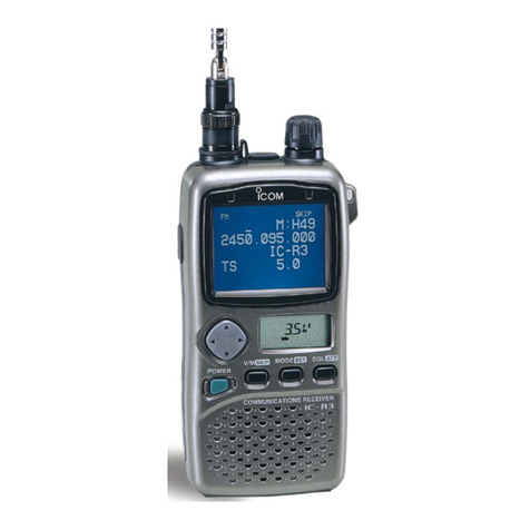
Other Icom Receiver manuals

Icom
Icom IC-910H User manual

Icom
Icom MXA-5000 User manual

Icom
Icom IC-PCR1500 User manual

Icom
Icom IC-R72 User manual

Icom
Icom MXA5000 01 User manual

Icom
Icom IC-R7100 User manual

Icom
Icom IC-RX7 User manual

Icom
Icom IC-R1500 User manual

Icom
Icom mxa- 5000 User manual

Icom
Icom IC-A110EURO Installation and operating instructions