Icom IC-7200 Service manual

IC-7200
HF/50 MHz
TRANSCEIVER
Quick Reference Manual
1. PASSBAND TUNING CONTROLS [TWIN PBT] Adjust the receiver‟s DSP filter passband width.
• The limit of the variable range depends on the passband width and mode. The limit of the variable range is half of the passband width,
and PBT is adjustable in 200 Hz (AM) or 50 Hz (other models) steps.
• Rotate both [TWIN PBT] controls (PBT1 and PBT2) to
the same position shifts the IF.
2. NOISE BLANKER KEY [NB]
➥Push to turn the noise blanker function ON or OFF.; appears on the display.
➥Push and hold for 1 sec to enter the noise blanker set mode for setting the noise blanker level and return to normal
operation.
• When entering the noise blanker set mode, the noise blanker function is automatically turned ON.
3. NR KEY [NR]
➥Push to turn the noise reduction function ON or OFF.; appears on the display.
➥Push and hold for 1 sec. to enter the noise reduction level set mode; push again to return to normal operation.
• When entering the noise reduction set mode, the noise reduction function is automatically turned ON.
4. ANF/METER KEY [ANF] METER
➥Push to turn the Automatic Notch Filter function ON or OFF.; appears on the display.
➥Push and hold for 1 sec. to toggle the meter function:
PO ➟SWR ➟ALC
• PO : indicates the relative RF output power.
• SWR : indicates the SWR over the transmission line.
• ALC : Indicates ALC level.
5. KEYPAD
6. RIT CONTROL INDICATOR
Lights orange when [M-CH] control (7) acts as the RIT control.
7. M-CH/RIT CONTROL [M-CH] (inner control)
➥While in the set mode/quick set mode, rotate to select the set mode item.
➥This control can act as the memory channel control or RIT control.
• The RIT function should be turned ON in advance to activate this control as RIT control.
- appears when the RIT function is turned ON.
• The RIT control indicator (6) lights orange when this control is activated as the RIT control.
➥During [M-CH] acting as the M-CH control:
•Rotate to select a memory channel.

➥During [M-CH] acting as RIT control:
Rotate to shift the receive frequency.
• Rotate the control clockwise to increase the frequency, or rotate the control
counterclockwise to decrease the frequency.
• The shift frequency range is +/- 9.999 kHz in 1 Hz steps or +/- 9.99 kHz in 10 Hz
steps.
8. MANUAL NOTCH FILTER CONTROL [MNF] (outer control)
Rotate to adjust the notch filter frequency to reject an interfering signal while the manual notch function is ON.
• The filter width can be set to narrow, middle or wide in the manual notch filter set mode accessed by push and hold the button
for more than 1 Second. Push it again to exit notch filter set mode.
9. M-CH/RIT•SET KEY
➥Push to toggle the [M-CH] control activation between memory channel control and RIT control.
• The RIT function should be turned ON in advance.
• The RIT control indicator (6) lights orange when the [M-CH] control functions as the RIT control.
➥Push and hold for 1 sec. to enter the quick set mode.
➥During quick set mode, push and hold for 1 sec. to enter the set mode.
➥During quick set mode or set mode, push to return to normal operation.
10. MODE KEY
➥Push momentarily to cycle through the
operating modes:
USB/LSB ➟CW/CW-R ➟RTTY/RTTY-R ➟
AM
➥Push and hold for 1 sec. to toggle the
following operating modes:
USB ↔LSB; CW ↔CW-R (Reverse);
RTTY ↔RTTY-R (Reverse)
• “CW-R” or “RTTY-R” appears on the display when reverse mode is selected.Note: Unused modes can be inhibited in set mode.
11. TUNING STEP KEY
➥Push to turn the programmable tuning step ON or OFF.
• “ ” appears above the 1 kHz indicator when the programmable tuning step is turned ON and the frequency can be changed in
programmed kHz steps.
➥While the programmable tuning step is turned ON (“ ” appears), push and hold for 1 sec. to enter tuning step set
mode; push again to return to normal operation.
• 0.1, 1, 5, 9 and 10 kHz programmable tuning steps
are available.
➥While the programmable tuning step is turned OFF, push and hold for 1 sec. to turn the 1 Hz step ON and OFF.
• 1 Hz indication appears, and the frequency can be changed in 1 Hz steps.
12. REAMP/ATTENUATOR KEY
➥Push to turn the preamp ON or OFF.
• “ ” appears on the display.
➥Push and hold for 1 sec. to turn the 20 dB attenuator ON; “ ” appears on the display.
• Push momentarily to turn the attenuator OFF.
13. MAIN DIAL [DIAL]
Changes the displayed frequency and selects values for selected set mode items, etc.
• About the [M-CH] control:
:ac

14. FILTER KEY
➥Push momentarily to cycle the IF filter settings between wide, middle and narrow for the selected operating mode.
➥Push and hold for 1 sec. to enter the filter set mode.
15. SPCH•LOCK KEY
➥Push to announce the selected frequency and S-meter level by the speech synthesizer.
• The parameters to be announced can be selected in the set mode.
➥Push and hold for 1 sec. to turn the dial lock function ON or OFF.
• The dial lock function electronically locks the main dial.
• ” appears while the dial lock function is ON.
16. POWER KEY
➥Push to turn power ON. (Turn the DC power supply ON in advance.)
➥Push and hold for 1 sec. to turn power OFF.
17. TUNER KEY
➥Push to turn the automatic antenna tuner function ON or OFF.
• An optional antenna tuner must be connected.
• appears on the display.
➥Push and hold for 1 sec. to manually tune the antenna tuner.
• An optional antenna tuner must be connected.
• When the tuner cannot tune the antenna, the tuning circuit is bypassed automatically after 20 sec.
18. RF GAIN/SQUELCH CONTROL [RF/SQL]
➥Adjusts the RF gain and squelch threshold level.
➥The squelch removes noise output from the speaker (closed condition) when no signal is received.
• The squelch is available for all modes.
• The control can be set as the squelch plus RF gain controls, squelch control only (RF gain is fixed at maximum) or Auto (RF gain
control in SSB, CW and RTTY; squelch control in AM) in set mode:
19. AF CONTROL [AF]
➥Varies the audio output level from the speaker.
20. HEADPHONE JACK [PHONES]
➥Accepts headphones with 8–16 Ω impedance.
• Output power: 5 mW with an 8 Ω load.
• When headphones are connected, no receive audio comes from the speaker.
21. MICROPHONE CONNECTOR [MIC]
➥Accepts supplied or optional microphone.

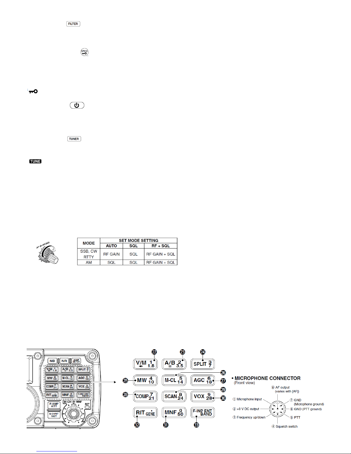
22. VFO/MEMORY/1/1.8 MHz BAND KEY
➥Push to toggle the operating mode between VFO mode or memory mode.
➥Push and hold for 1 sec. to copy the memory contents to VFO.
➥Push , then push this key to input the number „1.‟
➥Push and hold for 1 sec., then push this key to select the 1.8 MHz band.
23. VFO SELECT/EQUALIZATION/2/3.5 MHz BAND KEY
➥Push to toggle between VFO A and VFO B.
➥Push and hold for 1 sec. to equalize the frequency and operating mode of the two VFO‟s.
• The undisplayed VFO frequency and operating mode are set the same as the displayed VFO frequency and operating mode.
➥Push , then push this key to input the number „2.‟
➥Push and hold for 1 sec., then push this key to select the 3.5 MHz band.
24. SPLIT/3/7 MHz BAND KEY
➥Push to toggle the split function ON and OFF.
• appears on the display.
➥Push and hold for 1 sec. to activate the quick split function.
• The VFO B frequency and operating mode are set the same as the VFO A frequency and operating mode.
• Note: The quick split function can be turned OFF in the set mode.
➥Push , then push this key to input the number „3.‟
➥Push and hold for 1 sec., then push this key to select the 7 MHz band.
25. MEMORY WRITE/4/10 MHz BAND KEY
➥Push and hold for 1 sec. to store the displayed VFO frequency and mode into the selected memory channel.
➥Push , then push this key to input the number „4.‟
➥Push and hold for 1 sec., then push this key to select the 10 MHz band.
26. MEMORY CLEAR/5/14 MHz BAND KEY
➥Push and hold for 1 sec. to clear the displayed memory channel contents in memory mode.
• appears above the memory channel number.
➥Push and hold for 1 sec., to select a default condition or value when in set mode/quick set mode.
➥Push , then push this key to input the number „5.‟
➥Push and hold for 1 sec., then push this key to select the 14 MHz band.
27. AGC/6/18 MHz BAND KEY
➥Push to toggle the time constant for the AGC circuit fast and slow.
• “F.AGC” appears on the display when fast AGC is selected; no indication appears when slow AGC is selected.
➥Push and hold for 1 sec. to turn the AGC function OFF. ( “AGC-OFF” appears on the display.)
➥Push then push this key to input the number „6.‟
➥Push and hold for 1 sec., then push this key to select the 18 MHz band.
28. SPEECH COMPRESSOR/7/21 MHz BAND KEY
➥Push to turn the speech compressor function ON or OFF.
• appears on the display.
➥Push and hold for 1 sec. to enter speech compression level set; push again to return to normal operation.
➥Push , then push this key to input the number „7.‟
➥Push and hold for 1 sec., then push this key to select the 21 MHz band.

29. SCAN/8/24 MHz BAND KEY
➥Push to start/stop the programmed/memory scan in VFO/memory mode.
•appears on the display during scanning.
➥Push , then push this key to input the number ‘8.’
➥Push and hold for 1 sec., then push this key to select the 24 MHz band.
30. VOX/9/28 MHz BAND KEY
➥Push to turn the VOX function ON or OFF.
➥Push and hold for 1 sec. to enter VOX set mode; push again to return to normal operation.
➥Push , then push this key to input the number „9.‟
➥Push and hold for 1 sec., then push this key to select the 28 MHz band.
31. MANUAL NOTCH FILTER/0/50 MHz BAND KEY
➥Push to turn the manual notch filter function ON or OFF.
• appears on the display.
➥Push and hold for 1 sec. to enter the manual notch set mode; push again to return to normal operation.
Note: Before entering the set mode, the manual notch filter function is turned ON.
➥Push , then push this key to input the number „0.‟
➥Push and hold for 1 sec., then push this key to select the 50 MHz band.
32. RIT/•/GENERAL BAND KEY
➥Push to turn the RIT (Receiver Incremental Tuning) function ON or OFF.
•appears on the display.
• RIT frequency can be adjusted with [M-CH] control when RIT mode is selected.
➥Push and hold for 1 sec. to add the RIT shift frequency to the operating frequency.
• Note: Available only when the XFC (transmit frequency check function) is turned OFF.
➥Push , then push this key to input the number „• (decimal point).‟
➥Push and hold for 1 sec., then push this key to select the general coverage band.
33. FREQUENCY INPUT/ENTER/BAND KEY
➥Push to enter the direct frequency input condition.
➥Push and hold for 1 sec., then push a key on the keypad to select the operating band.
Note : selects the general coverage band.


Other manuals for IC-7200
6
Table of contents
Other Icom Transceiver manuals

Icom
Icom IC-9700 Installation and operating instructions

Icom
Icom IC-F7000 Installation and operating instructions

Icom
Icom M120 Service manual

Icom
Icom IC-F14 User manual

Icom
Icom IC-F4011 User manual

Icom
Icom IC-F1010 User manual

Icom
Icom IC-F4SR User manual

Icom
Icom IC-2800H User manual

Icom
Icom IC-A4 User manual

Icom
Icom IC-F51 User manual