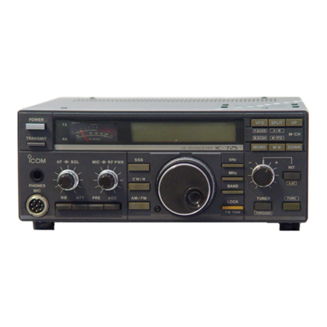
Icom IC-M400BB User manual

INSTRUCTION MANUAL
iM400BB
VHF MARINE TRANSCEIVER
This device complies with Part 15 of the FCC Rules. Opera-
tion is subject to the condition that this device does not cause
harmful interference.
COMMANDMIC
IV
™ (HM-195)
may not be supplied, depending
on the transceiver version.

i
FOREWORD
Thank you for purchasing this Icom product. The IC-M400BB
v h f m a r i n e t r a n s c e i v e r is designed and built with Icom’s
state of the art technology and craftsmanship. With proper
care, this product should provide you with years of trouble-
free operation.
We appreciate you making the IC-M400BB your radio of
choice, and hope you agree with Icom’s philosophy of “tech-
nology first.” Many hours of research and development went
into the design of your IC-M400BB.
FEATURESD
❍Built-in DSC meets ITU Class D requirement
❍Rugged waterproof construction
❍COMMANDMIC
IV
™ (HM-195) supplied*.
❍Easy to make an individual DSC calls using the
optional MA-500TR Class B AIS Transponder
* May not be supplied, depending on the transceiver version.
In that case, purchase separately.
IMPORTANT
READ ALL INSTRUCTIONS carefully and completely
before using the transceiver.
SAVE THIS INSTRUCTION MANUAL — This in-
struction manual contains important operating instructions
for the IC-M400BB.
EXPLICIT DEFINITIONS
WORD DEFINITION
RWARNING! Personal injury, fire hazard or electric
shock may occur.
CAUTION Equipment damage may occur.
NOTE
If disregarded, inconvenience only. No risk
of personal injury, fire or electric shock.
CLEAN THE TRANSCEIVER AND MICROPHONE THOR-
OUGHLY WITH FRESH WATER after exposure to water
including salt, otherwise, the keys and switch may become
inoperable due to salt crystallization.

IN CASE OF EMERGENCY
If your vessel requires assistance, contact other vessels and
the Coast Guard by sending a Distress call on Channel 16.
Or, transmit your Distress call using digital selective calling
on Channel 70.
INSTALLATION NOTE
Installation:
The installation of this equipment should be made in such a
manner as to respect the EC recommended electromagnetic
field exposure limits. (1999/519/EC)
The maximum RF power available from this device is 25
watts. The antenna should be installed as high as possible
for maximum efficiency and the installation height should be
at least 1.4 meters above any accessible position. In the case
where an antenna cannot be installed at a reasonable height,
then the transmitter should neither be continuously operated
for long periods if any person is within a distance of 1.4 me-
ters of the antenna, nor operated at all if any person is touch-
ing the antenna.
It is recommended that antenna of a maximum gain of 3 dB
are used. If higher gain antenna are required then please
contact your Icom distributor for revised installation recom-
mendations.
Operation:
The exposure to RF electromagnetic field is only applicable
when this device is transmitting. This exposure is naturally re-
duced due to the nature of alternating periods of receiving and
transmitting. Keep your transmissions to the minimum neces-
sary.
USING CHANNEL 16
DISTRESS CALL PROCEDURE
1. “MAYDAY MAYDAY MAYDAY.”
2. “THIS IS ...............” (name of vessel).
3. Say your call sign or other description of the vessel (AND
9 digit DSC ID if you have one).
4. “LOCATED AT ...............” (your position).
5. State the nature of the distress and assistance required.
6. Give any other information which might facilitate the res-
cue.
USING DIGITAL SELECTIVE CALLING (Ch 70)
DISTRESS CALL PROCEDURE
1. While lifting up the key cover, hold down [DISTRESS]
for 3 seconds until you hear 3 short beeps and then one
long beep.
2. Wait for an acknowledgment on Channel 70 from a coast
station.
•After the acknowledgement is received, Channel 16 is auto-
matically selected.
3. Hold down [PTT], then transmit the appropriate informa-
tion as listed above.
ii

iii
RADIO OPERATOR WARNING
WARNING
Icom requires the radio operator to meet the
FCC and IC Requirements for Radio Fre-
quency Exposure. An omnidirectional antenna
with gain not greater than 9 dBi must be
mounted a minimum of 5 meters (measured
from the lowest point of the antenna) vertically
above the main deck and all possible personnel. This is the
minimum safe separation distance estimated to meet all RF
exposure compliance requirements. This 5 meter distance is
based on the FCC and IC Safe Maximum Permissible Expo-
sure (MPE) distance of 3 meters added to the height of an
adult (2 meters) and is appropriate for all vessels.
For watercraft without suitable structures, the antenna must
be mounted so as to maintain a minimum of 1 meter verti-
cally between the antenna, (measured from the lowest point
of the antenna), to the heads of all persons AND all persons
must stay outside of the 3 meter MPE radius.
Do not transmit with radio and antenna when persons are
within the MPE radius of the antenna, unless such persons
(such as driver or radio operator) are shielded from antenna
field by a grounded metallic barrier. The MPE Radius is the
minimum distance from the antenna axis that person should
maintain in order to avoid RF exposure higher than the al-
lowable MPE level set by FCC and IC.
FAILURE TO OBSERVE THESE LIMITS MAY ALLOW
THOSE WITHIN THE MPE RADIUS TO EXPERIENCE RF
RADIATION ABSORPTION WHICH EXCEEDS THE MAXI-
MUM PERMISSIBLE EXPOSURE (MPE) LIMIT.
IT IS THE RESPONSIBILITY OF THE RADIO OPERATOR
TO ENSURE THAT THE MAXIMUM PERMISSIBLE EXPO-
SURE LIMITS ARE OBSERVED AT ALL TIMES DURING
RADIO TRANSMISSION. THE RADIO OPERATOR IS TO
ENSURE THAT NO BYSTANDERS COME WITHIN THE
RADIUS OF THE MAXIMUM PERMISSIBLE EXPOSURE
LIMITS.
Determining MPE Radius
THE MAXIMUM PERMISSIBLE EXPOSURE (MPE) RA-
DIUS HAS BEEN ESTIMATED TO BE A RADIUS OF
ABOUT 3M PER OET BULLETIN 65 OF THE FCC.
THIS ESTIMATE IS MADE ASSUMING THE MAXIMUM
POWER OF THE RADIO AND ANTENNAS WITH A MAXI-
MUM GAIN OF 9dBi ARE USED FOR A SHIP MOUNTED
SYSTEM.

iv
AVERTISSEMENT POUR LES OPÉRATEURS RADIO
Icom exige que l'opérateur radio se conforme
aux exigences de la FCC et d’IC en matière
d'exposition aux radiofréquences. Une antenne
omnidirectionnelle dont le gain ne dépasse pas
9dBi doit être fixée à une distance minimale de
5 mètres (mesurée depuis le point le plus bas
de l'antenne) verticalement au-dessus du pont principal et de tout
le personnel qui peut s'y trouver. Il s'agit de la distance de sécurité
minimale prévue pour satisfaire aux exigences de conformité en mat-
ière d'exposition aux RF. Cette distance de 5 mètres est établie en
fonction de l'exposition maximale admissible sécuritaire de 3 mètres
établie par la FCC et d’IC, à laquelle on ajoute la hauteur d'un adulte
(2 mètres); cette distance convient pour tous les navires.
Dans le cas des embarcations sans structure convenable, l'antenne
doit être fixée de façon à maintenir une distance minimale de 1 mètre
verticalement entre cette antenne (mesurée depuis son point le plus
bas) et la tête de toute personne présente; toutes les personnes
présentes doivent se tenir à l'extérieur d'un rayon d'exposition maxi-
male admissible de 3 mètres.
Ne pas émettre à l'aide de la radio et de l'antenne lorsque des
personnes se trouvent à l'intérieur du rayon d'exposition maximale
admissible de cette antenne, à moins que ces personnes (comme
le conducteur ou l'opérateur radio) ne soient protégées du champ
de l'antenne par un écran métallique relié à la masse. Le rayon
d'exposition maximale admissible équivaut à la distance minimale
que cette personne doit maintenir entre elle et l'axe de l'antenne pour
éviter une exposition aux RF supérieure au niveau d'exposition maxi-
male admissible fixé par la FCC et d’IC.
LE NON-RESPECT DE CES LIMITES PEUT CAUSER, POUR LES
PERSONNES SITUÉES DANS LE RAYON D'EXPOSITION MAXI-
MALE ADMISSIBLE, UNE ABSORPTION DE RAYONNEMENT DE
RF SUPÉRIEURE À L'EXPOSITION MAXIMALE ADMISSIBLE
FIXÉE.
L'OPÉRATEUR RADIO EST RESPONSABLE D'ASSURER QUE
LES LIMITES D'EXPOSITION MAXIMALE ADMISSIBLE SOIENT
RESPECTÉES EN TOUT TEMPS PENDANT LA TRANSMISSION
RADIO. L'OPÉRATEUR RADIO DOIT S'ASSURER QU'AUCUNE
PERSONNE PRÉSENTE NE SE SITUE À L'INTÉRIEUR DU RAY-
ON D'EXPOSITION MAXIMALE ADMISSIBLE.
Établir le rayon d'exposition maximale admissible
ON ESTIME QUE LE RAYON D'EXPOSITION MAXIMALE ADMIS-
SIBLE EST D'ENVIRON 3 M, TEL QUE STIPULÉ DANS LE BUL-
LETIN OET 65 DE LA FCC. CETTE DISTANCE ESTIMÉE TIENT
COMPTE D'UN SYSTÈME INSTALLÉ SUR UN NAVIRE UTILISANT
LA PUISSANCE MAXIMALE DE LA RADIO ET DES ANTENNES
DONT LE GAIN MAXIMAL EST DE 9dBi.
AVERTISSEMENT

v
COUNTRY CODE LIST
• ISO 3166-1
Country Codes Country Codes
1
2
3
4
5
6
7
8
9
10
11
12
13
14
15
16
17
Austria
Belgium
Bulgaria
Croatia
Czech Republic
Cyprus
Denmark
Estonia
Finland
France
Germany
Greece
Hungary
Iceland
Ireland
Italy
Latvia
AT
BE
BG
HR
CZ
CY
DK
EE
FI
FR
DE
GR
HU
IS
IE
IT
LV
18
19
20
21
22
23
24
25
26
27
28
29
30
31
32
33
Liechtenstein
Lithuania
Luxembourg
Malta
Netherlands
Norway
Poland
Portugal
Romania
Slovakia
Slovenia
Spain
Sweden
Switzerland
Turkey
United Kingdom
LI
LT
LU
MT
NL
NO
PL
PT
RO
SK
SI
ES
SE
CH
TR
GB
• FOR CLASS A UNINTENTIONAL RADIATORS:
This equipment has been tested and found to comply with the
limits for a Class A digital device, pursuant to part 15 of the
FCC Rules. These limits are designed to provide reasonable
protection against harmful interference when the equipment
is operated in a commercial environment. This equipment
generates, uses, and can radiate radio frequency energy
and, if not installed and used in accordance with the instruc-
tion manual, may cause harmful interference to radio com-
munications.
Operation of this equipment in a residential area is likely to
cause harmful interference in which case the user will be re-
quired to correct the interference at his own expense.
FCC INFORMATION
NOTE
A WARNING STICKER is supplied with the U.S.A. version
transceiver.
To comply with FCC regulations, this sticker must be affixed in
such a location as to be readily seen from the operating con-
trols of the radio as in the diagram below. Make sure the chosen
location is clean and dry before applying the sticker.

vi
New2001
PRECAUTIONS
RWARNING! NEVER
connect the transceiver to an AC
outlet. This may pose a fire hazard or result in an electric shock.
RWARNING! NEVER connect the transceiver to a pow-
er source of more than 16 V DC or use reverse polarity. This
will ruin the transceiver.
RWARNING! NEVER cut the DC power cable between
the DC plug at the back of the transceiver and fuse holder. If
an incorrect connection is made after cutting, the transceiver
may be damaged.
CAUTION: NEVER
place the transceiver where normal
operation of the vessel may be hindered or where it could
cause bodily injury.
KEEP the transceiver and microphone at least 1 m away
from the vessel’s magnetic navigation compass.
DO NOT use or place the transceiver in areas with tem-
peratures below –20°C (–4°F) or above +60°C (+140°F) or, in
areas subject to direct sunlight, such as the dashboard.
DO NOT use harsh solvents such as benzine or alcohol to
clean the transceiver, as they will damage the transceiver’s
surfaces. If the transceiver becomes dusty or dirty, wipe it
clean with a soft, dry cloth.
DO NOT disassemble or modify the transceiver for any rea-
son.
BE CAREFUL! The transceiver rear panel will become
hot when operating continuously for long periods of time.
Place the transceiver in a secure place to avoid inadvertent
use by children.
BE CAREFUL! The transceiver and the supplied or op-
tional HM-195 c o m m a n d m i c i v ™meet IPX7 requirements
for waterproof protection. However, once the transceiver has
been dropped, waterproof protection cannot be guaranteed
because of possible damage to the transceiver’s case or the
waterproof seal.
* Except for the DC power connector, NMEA In/Out leads and AF
Out leads.
For U.S.A. only
CAUTION: Changes or modifications to this device, not ex-
pressly approved by Icom Inc., could void your authority to
operate this device under FCC regulations.
Icom, Icom Inc. and the Icom logo are registered trademarks of Icom Incor-
porated (Japan) in Japan, the United States, the United Kingdom, Germany,
France, Spain, Russia and/or other countries.
COMMANDMIC is a registered trademark of Icom Incorporated (Japan) in Ja-
pan and the United States.

vii
New2001
TABLE OF CONTENTS
FOREWORD .........................................................................i
IMPORTANT.......................................................................... i
EXPLICIT DEFINITIONS....................................................... i
IN CASE OF EMERGENCY................................................. ii
INSTALLATION NOTE.......................................................... ii
RADIO OPERATOR WARNING .......................................... iii
AVERTISSEMENT POUR LES OPÉRATEURS RADIO...... iv
FCC INFORMATION ............................................................ v
NOTE....................................................................................v
COUNTRY CODE LIST........................................................ v
PRECAUTIONS................................................................... vi
TABLE OF CONTENTS...................................................... vii
1 OPERATING RULES.......................................................1
2 PREPARATION............................................................2–3
MMSI code programming■.............................................2
ATIS code programming■...............................................3
3 AIS TRANSPONDER...................................................4–5
Making an Individual call using an AIS transponder■....4
4 CONNECTIONS AND MAINTENANCE ....................6–10
Connections■.................................................................6
Supplied accessories■...................................................8
Fuse replacement■........................................................8
Cleaning■.......................................................................8
Mounting the transceiver■..............................................8
Antenna■........................................................................8
Microphone installation■................................................9
5 SPECIFICATIONS AND OPTIONS .........................11–12
Specifications■.............................................................11
Options■.......................................................................12
6 CHANNEL LIST.......................................................13–14
7 TROUBLE SHOOTING..................................................15

1
New2001
1
OPERATING RULES
1
2
3
4
5
6
7
8
9
10
11
12
13
14
15
16
PrioritiesD
•Readallrules and regulations pertaining to call priorities,
and keep an up-to-date copy handy. Safety and distress
calls take priority over all others.
•YoumustmonitorChannel16whenyouarenotoperating
on another channel.
•Falseorfraudulentdistresscallsareprohibitedunderlaw.
PrivacyD
•Informationoverheard,butnotintendedforyou,cannotlaw-
fully be used in any way.
•Indecentorprofanelanguageisprohibited.
Radio licensesD
(1) SHIP STATION LICENSE
You may require a current radio station license before using
the transceiver. It is unlawful to operate a ship station which is
not licensed, but required to be.
If required, contact your dealer or the appropriate govern-
ment agency for a Ship-Radiotelephone license application.
This government-issued license states the call sign which is
your craft’s identification for radio purposes.
(2) OPERATOR’S LICENSE
A Restricted Radiotelephone Operator Permit is the license
most often held by small vessel radio operators when a radio
is not required for safety purposes.
If required, the Restricted Radiotelephone Operator Permit
must be posted or kept with the operator. If required, only a
licensed radio operator may operate a transceiver.
However, non-licensed individuals may talk over a transceiver
if a licensed operator starts, supervises, ends the call and
makes the necessary log entries.
A current copy of the applicable government rules and regu-
lations is only required to be on hand for vessels in which
a radio telephone is compulsory. However, even if you are
not required to have these on hand it is your responsibility to
be thoroughly acquainted with all pertinent rules and regula-
tions.
NOTE: Even though the transceiver is capable of opera-
tion on VHF marine channels 3, 21, 23, 61, 64, 81, 82 and
83, according to FCC regulations these simplex channels
cannot be lawfully used by the general population in USA
waters.

2
New2001New2001
PREPARATION
2
MMSI code programming■
The 9 digit MMSI (Maritime Mobile Service Identity: DSC self
ID) code can be programmed at power ON.
The code is programmed by using the HM-195.
This initial code setting can be performed only once.
After being set, it can be changed by only your dealer
or distributor. If your MMSI code has already been pro-
grammed, this programming is not necessary.
Hold down [PWR](Dial) to turn ON the power.q
•Threeshortbeepssound,and“NODSCMMSI”isdisplayed.
Push [ENT] to start the MMSI code programming.w
•Push[CLEAR]twicetocanceltheprogramming,andgotothe
normal operating screen. In this case, the transceiver cannot
make a DSC call. To program the MMSI code, turn OFF the
power, then turn it ON again.
Enter your MMSI code in the following manner:e
•SelectadesirednumberusingDial,or[∫]/[√]/[Ω]/[≈].
•Push[ENT]orDialtosetit.
•Tomovethecursor,selecteitherarrow,“←” or “→,” then push
[ENT] or Dial.
Repeat stepr e to enter all 9 digits.
After entering the 9 digit code, “FINISH” is automaticallyt
selected, and then push [ENT] or Dial to set it.
The “MMSI CONFIRMATION” screen is displayed.y
Enter your MMSI code again for confirmation.u
•Enterinthesamemannerasstepsethrough t.
When your MMSI code programming is successfully com-i
pleted, the screen as shown below is briefly displayed.
•Afterthat,thenormaloperatingscreenisdisplayed.
The programmed MMSI code can be checked in the MENU
screen.
NOTE: Depending on the transceiver version, the ATIS
code programming may be required after programming the
MMSI code. See the next page for details.

3
2
PREPARATION
New2001
1
2
3
4
5
6
7
8
9
10
11
12
13
14
15
16
New2001
The 10 digit ATIS (Automatic Transmitter Identification Sys-
tem) code can be programmed at power ON.
The code is programmed by using the HM-195.
This initial code setting can be performed only once.
After being set, it can be changed by only your dealer
or distributor. If your ATIS code has already been pro-
grammed, this programming is not necessary.
After programming the MMSI code, “Push [ENT] to Regis-q
ter Your ATIS” is displayed.
Push [ENT] to start the ATIS code programming.w
•Push[CLEAR]twicetocanceltheprogramming,andgotothe
normal operating mode. In this case, the ATIS function is dis-
abled. To program the ATIS code, turn OFF the power, then turn
it ON again.
Enter your ATIS code in the following manner:e
•SelectadesirednumberusingDial,or[∫]/[√]/[Ω]/[≈].
•Push[ENT]orDialtosetit.
•Tomovethecursor,selecteitherarrow,“←” or “→,” then push
[ENT] or Dial.
Repeat stepr e to enter all 10 digits.
After entering the 10 digit code, “FINISH” is automaticallyt
selected, and then push [ENT] or Dial to set it.
The “ATIS CONFIRMATION” screen is displayed.y
Enter your ATIS code again for confirmation.u
•Enterinthesamemannerasstepsethrough t.
When your ATIS code programming is successfully com-i
pleted, the screen shown below is briefly displayed.
•Afterthat,thenormaloperatingscreenisdisplayed.
The programmed ATIS code can be checked in the MENU
screen.
ATIS code programming■(For Dutch version transceivers)

4
New2001New2001
AIS TRANSPONDER
3
When the optional MA-500TR CLASS B AIS TRANSPONDER is
connected to your transceiver, an individual DSC call can be
transmitted to a selected AIS target, without needing to enter
the target’s MMSI code. In this case, the call type is automati-
cally set to Routine.
See page 7 for connecting instructions.
To ensure correct operation of the DSC function, make
sure you correctly set the CH70 SQL LEVEL. See (¤5) of
the HM-195 instruction manual.
Step 1: Transponder’s operation
Select a desired AIS target on the plotter, target list or dan-q
ger list display.
•Youcanalsogotothenextstepwheneverthedetailscreenof
the AIS target is displayed.
•Makesurethetransceiverisinthenormaloperatingmode.Oth-
erwise, you cannot make an individual DSC call using the tran-
sponder.
Push [DSC] to display the voice channel selection screen,w
and then push [Y] or [Z] to select a desired voice chan-
nel*.
•Voicechannelsarealreadypresetintothetransponderinrecom-
mended order.
*When a coast station is selected in step q, a voice channel will
be specified by the coast station, therefore you cannot change
the channel. The transponder will display “Voice Channel is
specified by the Base station,” in this case.
Push [DSC] to transmit an individual DSC call to the AISe
target.
•IfChannel70isbusy,thetransceiverstandsbyuntilthechannel
becomes clear.
•Ifthetransceivercannotmakethecall,thetransponderwilldis-
play “DSC Transmission FAILED.”
Making an Individual call using an AIS transponder■
Transponder’s display
Microphone’s display

New2001
5
3
AIS TRANSPONDER
New2001
1
2
3
4
5
6
7
8
9
10
11
12
13
14
15
16
After making the individual DSC call, the transponder willr
display “DSC Transmission COMPLETED.”
•Push[CLEAR]toreturntothescreendisplayedbeforeyouen-
tered the voice channel selection screen in step w.
•ThetransceiverstandsbyonChannel70untilanacknowledge-
ment is received.
Step 2: Transceiver’s operation
When the acknowledgement is received, beeps sound.t
If the acknowledgement➥‘Able to comply’ is received,
push [ALARM OFF] to stop the beeps, and then select
the intership channel specified in step w.
•Adifferentintershipchannelwillbeselectedifthestationyou
called cannot use the channel.
•Toreply,push[PTT]andspeakatanormalvoicelevel.
•YoucanchecktheMMSIcodeorthename,ifprogrammed,
of the AIS target on the display.
If the acknowledgement➥‘Unable to comply’ is received,
push [ALARM OFF] to stop the beeps, and then return
to the operating channel before you entered the MENU
screen.
y
After the communication is finished, push [EXIT] to return
to the normal operating mode.
Transponder’s display
Microphone’s display
[DSC]
[CLEAR]
[Z]
[Y]
TRANSPONDER
‘Able to comply’ is received
‘Unable to comply’ is received

6
New2001New2001
CONNECTIONS AND MAINTENANCE
4
New2001
Connections■
y
t
e
r
q
w
qANTENNA CONNECTOR
Connects to a marine VHF antenna cable’s PL-259 con-
nector.
CAUTION: Transmitting without an antenna may dam-
age the transceiver.
wNMEA IN/OUT LEADS
Brown: Talker B (Data-L)
Connects to an NMEA In Negative line of a PC or
NMEA0183 ver. 3.01 sentence format DSC, DSE compat-
ible navigation equipment, to receive position data from
other ships.
White: Talker A (Data-H)
Connects to an NMEA In Positive line of a PC or NMEA0183
ver. 3.01 sentence format DSC, DSE compatible naviga-
tion equipment, to receive position data from other ships.
Green: Listener B (Data-L)
Connects to an NMEA Out Negative line of a GPS receiver
for position data.
•ANMEA0183ver.2.0or3.01RMC,GGA,GNS,GLLandVTG
sentence format compatible GPS receiver is required. Ask your
dealer about suitable GPS receivers.
Yellow: Listener A (Data-H)
Connects to an NMEA Out Positive line of a GPS receiver
for position data.
•ANMEA0183ver.2.0or3.01RMC,GGA,GNS,GLLandVTG
sentence format compatible GPS receiver is required. Ask your
dealer about suitable GPS receivers.
eAF OUT LEADS
Orange: Public Address Speaker (+)
Gray: Public Address Speaker (–)
Connects to a PA speaker.
•PAoutputpower:Morethan10Wat10%distortionwitha4˘load
Both black and blue leads are used only for maintenance
purpose.
NOTE for NMEA In/Out and AF Out leads:
The connectors are attached to keep the leads together.
Before connecting to a piece of equipment, you should cut
the leads to remove the connector.

New2001New2001
7
4
CONNECTIONS AND MAINTENANCE
New2001
1
2
3
4
5
6
7
8
9
10
11
12
13
14
15
16
rDC POWER CONNECTOR
Connects to a 13.8 V DC power source.
MAKE SURE the DC power cable polarity is correct.
Red : Positive + terminal
Black : Negative _ terminal
CAUTION: After connecting the DC power cable, NMEA
leads, external speaker leads and PA speaker leads, cover
the connector and leads with an adhesive tape, as shown
below, to prevent water seeping into the connection.
tGROUND TERMINAL
Connects to a vessel ground to prevent electrical shocks
and interference from other equipment occurring. Use a
PH M3 ×6 screw (not supplied).
yCOMMAND MICROPHONE JACK
Connects to the HM-195.
NOTE: For those who purchased the IC-M400BB and HM-195
separately.
When connecting the
HM-195 for the first time,
a firmware update (if
needed) will automatically
start, and the monitor dis-
plays the message shown
to the right. The update
will take a maximum of 2
minutes.
DO NOT turn OFF the transceiver, or disconnect the microphone
until the update is completed.
Connect to the MA-500TRD
Connect the transceiver to the high-density D-Sub 15-pin
connector of the MA-500TR using the OPC-2014* cable. Af-
ter connecting, an Individual DSC call can be made to the
AIS target using the transponder, without entering the target’s
MMSI code.
* The OPC-2014 is supplied with the MA-500TR
• Listener A (Data-H) lead (Yellow):
Connects to lead 3 of the OPC-2014.
• Listener B (Data-L) lead (Green):
Connects to lead 2 of the OPC-2014.
• Talker A (Data-H) lead (White):
Connects to lead 5 of the OPC-2014.
• Talker B (Data-L) lead (Brown):
Connects to lead 4 of the OPC-2014.
Rubber vulcanizing
tape

8
4CONNECTIONS AND MAINTENANCE
New2001
Supplied accessories■
DC power cable
(OPC-891A)
Screws (5×20 mm)
Flat washers (M5)
Spring washers (M5)
Fuse replacement■
One fuse is installed in the supplied DC power cable. If the
fuse blows or the transceiver stops functioning, track down
the source of the problem, repair it, and replace the damaged
fuse with a new one of the proper rating.
Fuse rating: 10 A
Cleaning■
If the transceiver becomes dusty or dirty, wipe it clean with a
soft, dry cloth.
DO NOT use harsh solvents such as benzine or
alcohol, as they will damage transceiver surfaces.
Mounting the transceiver■
Using the supplied template on the leaflet, mount the IC-
M400BB securely to a surface which is more than 10 mm
thick and can support more than 5 kg using the 4 supplied
screws (5 ×20 mm), as illustrated below.
KEEP the transceiver and microphone at least 1 meter
away from the vessel’s magnetic navigation compass.
Spring washer
Flat washer
Secure the transceiver
to a flat surface using
the supplied screws, as
shown in the illustration.
Screws
Antenna■
A key element in the performance of any communication sys-
tem is the antenna. Ask your dealer about antennas and the
best place to mount them.

9
4
CONNECTIONS AND MAINTENANCE
New2001
1
2
3
4
5
6
7
8
9
10
11
12
13
14
15
16
Microphone installation■
The HM-195 should be connected to the transceiver using
the supplied OPC-1540 connection cable. The cable is used
to operate from a longer distance. The cable connector can
also be installed as a built-in plug on a cabinet or wall.
To operate from even longer distances, the optional 6 meter
long OPC-1541 extension cable can be used between the
transceiver and the OPC-1540. Up to two OPC-1541 can be
added.
InstallationD
Insert the OPC-1540 cable connector into the commandq
microphone jack, and tighten the nut.
To use the cable connector as a wall socket, install it asw
described to the right.
Using the mounting base as a template, carefully mark thee
holes where the cable and three screws will be fastened.
Drill holes at these marks.r
Install the mounting base using the supplied screws, ast
shown below.
Gasket
Cap
Mounting base Nut
Screw holes
(approximately 2 mm; 3⁄32˝ (d))
The completed installation should look like this.y

10
4CONNECTIONS AND MAINTENANCE
New2001 New2001
10
Gasket
Mounting base
Cap
Nut

11
5
SPECIFICATIONS AND OPTIONS
New2001
1
2
3
4
5
6
7
8
9
10
11
12
13
14
15
16
Specifications■
GeneralD
•Frequencycoverage
European versions : Tx 156.000–161.450 MHz
Rx 156.000–163.425 MHz
USA versions : Tx 156.025–157.425 MHz
Rx 156.050–163.275 MHz
•Mode :
FM (16K0G3E),
DSC (16K0G2B)
•Channelspacing :25kHz
•Operatingtemp.range :–20°C to +60°C ; –4°F to +140°F
•Currentdrain(at13.8V) :TXhigh 5.5Amaximum
Max. audio 3.5 A maximum
•Powersupplyrequirement :13.8VDCnominal
(negative ground)
•Frequencystability :±1.5kHz (–20°C to +60°C)
•Antennaimpedance :50˘nominal
•Dimensions(approximately) :216(W) ×79(H) ×125(D) mm
(Projections not included) ; 8.5(W) × 3.1(H)×4.9(D) inches
•Weight (approximately) : 830 g ; 29 oz
TransmitterD
•Outputpower :25W/1W
•Modulationsystem :Variablereactancefrequency
modulation
•Max.frequencydeviation :±5.0kHz
•Spuriousemissions
European versions : Less than 0.25 µW
USA versions : Less than –70 dBc (High)
Less than –56 dBc (Low)
ReceiverD
•Receivesystem :Doubleconversion
superheterodyne
•Sensitivity
European versions
(20 dB SINAD) : –5 dBµ emf (typical)
USA versions
(12 dB SINAD) : –13 dBµ (typical)
•Squelchsensitivity
European versions : Less than –2 dBµ emf
USA versions : Less than –10 dBµ
•Intermodulationrejectionratio
European versions : More than 68 dB
USA versions : More than 70 dB
•
Spurious response rejection ratio
: More than 70 dB
•Adjacentchannelselectivity :Morethan70dB
•Audiooutputpower :Morethan10Wat10%distortion
with a 4 ˘load (RX SP)
:More than 2W at 10% distortion
with a 4 ˘load (HM-195)
All stated specifications are subject to change without notice
or obligation.

12
5SPECIFICATIONS AND OPTIONS
New2001 New2001
DimensionsD
42 (1.65)
79 (3.11)
Unit: mm (inch)
190 (7.48)
216 (8.5)
165 mm (6.49)
124.5 (4.9)
108.3 (4.26)
Options■
•HM-195 c o m m a n d m i c i v ™
External microphone-type controller. 6 m (20 ft) microphone
cable included. Black and white colors are available.
•OPC-1541 m i c r o p h o n e e x t e n s i o n c a b l e
6 m (20 feet) microphone extension cable for the HM-195
c o m m a n d m i c i v ™. Up to two OPC-1541 can be connected.
Maximum usable length is 18 m (60 ft).
•MA-500TR c l a s s ba i s t r a n s p o n d e r
To transmit individual DSC calls to selected AIS targets.
Approved Icom optional equipment is designed for optimal perfor-
mance when used with an Icom transceiver.
Icom is not responsible for the destruction or damage to an Icom
transceiver in the event the Icom transceiver is used with equipment
that is not manufactured or approved by Icom.
Other manuals for IC-M400BB
2
Table of contents
Other Icom Transceiver manuals

Icom
Icom IC-A25 Installation guide

Icom
Icom IC-9700 Setup guide

Icom
Icom VHF IC-F50 Installation and operating instructions

Icom
Icom IC-V200 User manual

Icom
Icom IC-7800 User manual

Icom
Icom IC-M87 User manual

Icom
Icom iM423 User manual

Icom
Icom IC-E92D User manual

Icom
Icom IC-F33GT User manual

Icom
Icom ID-51A Installation guide
Popular Transceiver manuals by other brands

Technisonic Industries Limited
Technisonic Industries Limited TFM-530 Installation and operating instructions

Marmitek
Marmitek Home Control TM13 user manual

Four State QRP Group
Four State QRP Group Cyclone 40 instruction manual

Entel
Entel HT644 GMDSS user guide

Codan
Codan 5700 series Reference manual

Tait
Tait T2020 Series II user guide