Sommerkamp TS-5030P User manual


Table of contents
Languages:
Other Sommerkamp Transceiver manuals
Sommerkamp
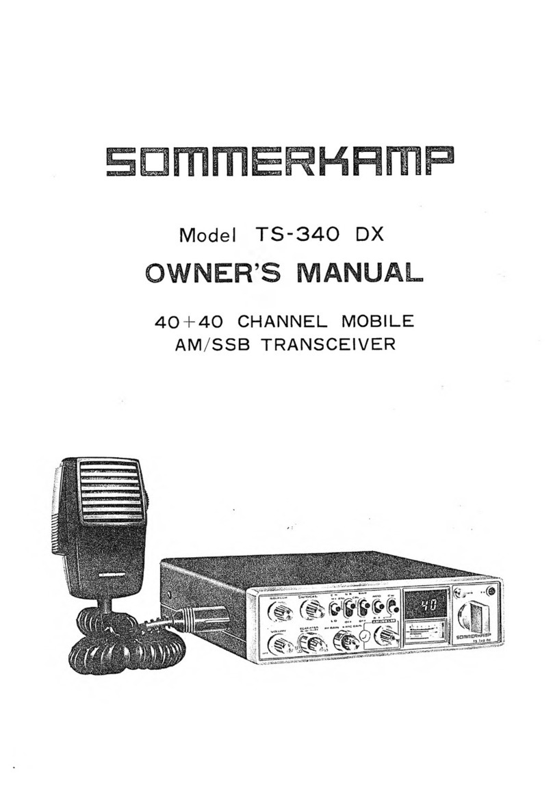
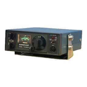
Sommerkamp TS-340 DX User manual
Sommerkamp
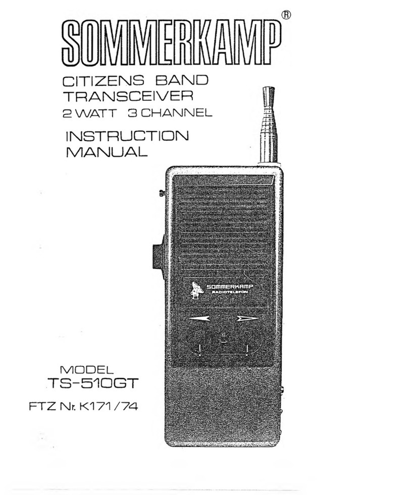
Sommerkamp TS-680DX User manual
Sommerkamp
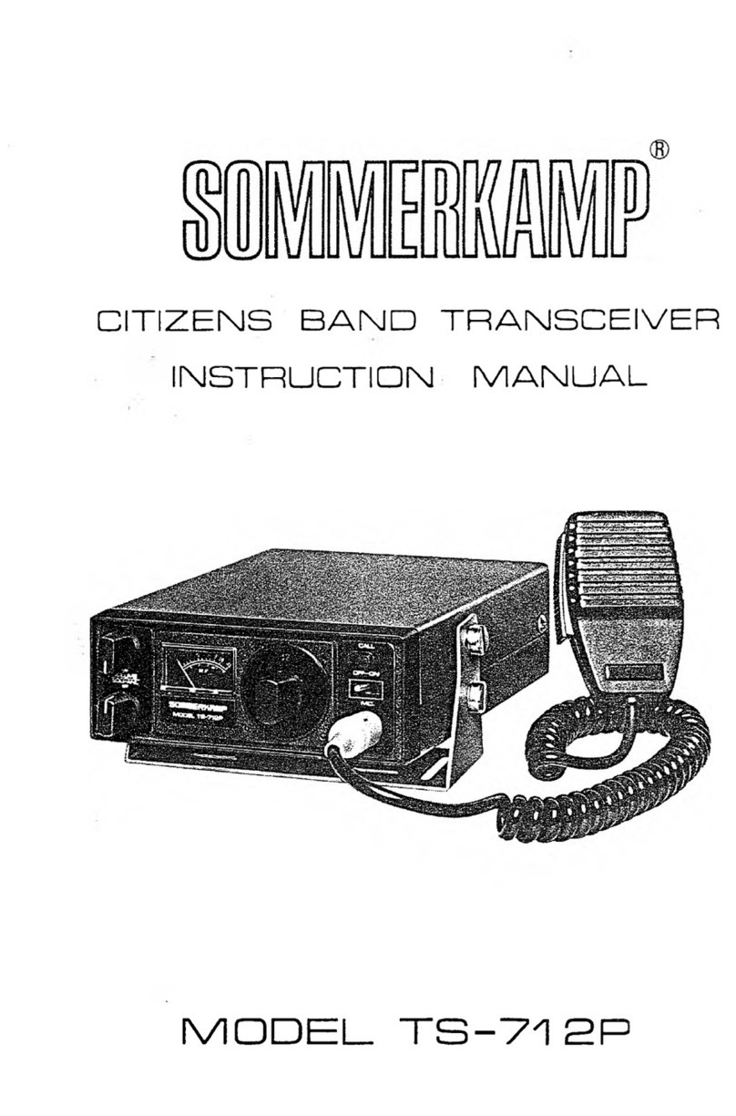
Sommerkamp TS-510GT User manual
Sommerkamp
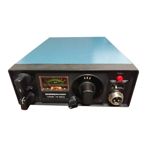
Sommerkamp TS-712P User manual
Sommerkamp
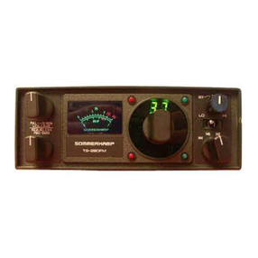
Sommerkamp TS-660S User manual
Sommerkamp
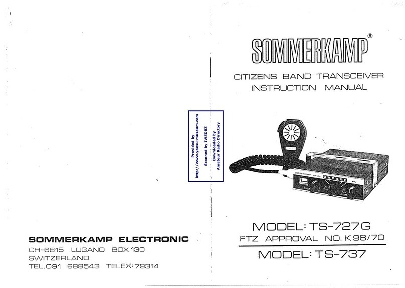
Sommerkamp TS 280 FM User manual
Sommerkamp
Sommerkamp TS-727G User manual

Sommerkamp
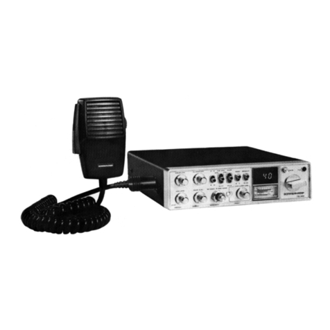
Sommerkamp TS -1122FM User manual
Sommerkamp
Sommerkamp TS-340 User manual
Sommerkamp
Sommerkamp FT DX-500 User manual

Sommerkamp
Sommerkamp TS-727G User manual
Sommerkamp
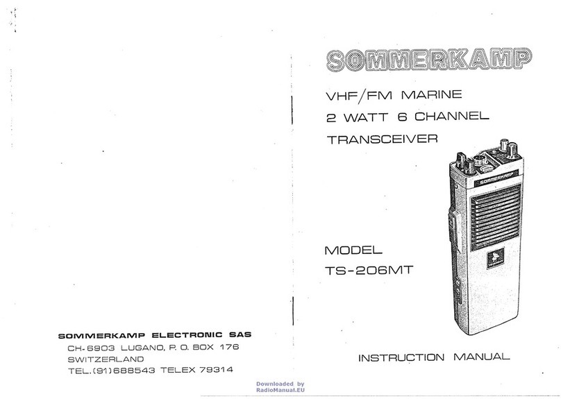
Sommerkamp TS-206MT User manual
Sommerkamp
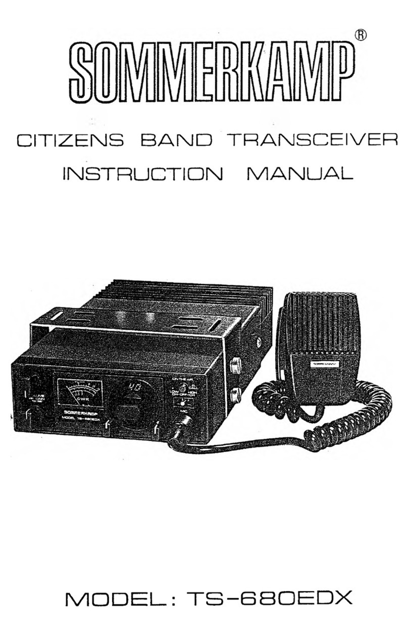
Sommerkamp TS-680EDX User manual
Sommerkamp
Sommerkamp TS 600 G User manual

Sommerkamp
Sommerkamp TS-727GT User manual
Sommerkamp
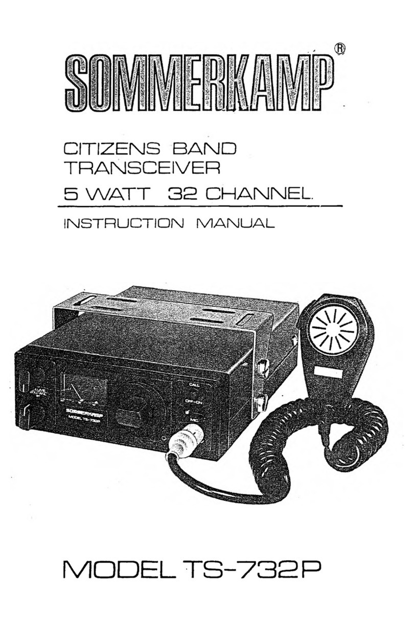
Sommerkamp TS-732P User manual
Sommerkamp
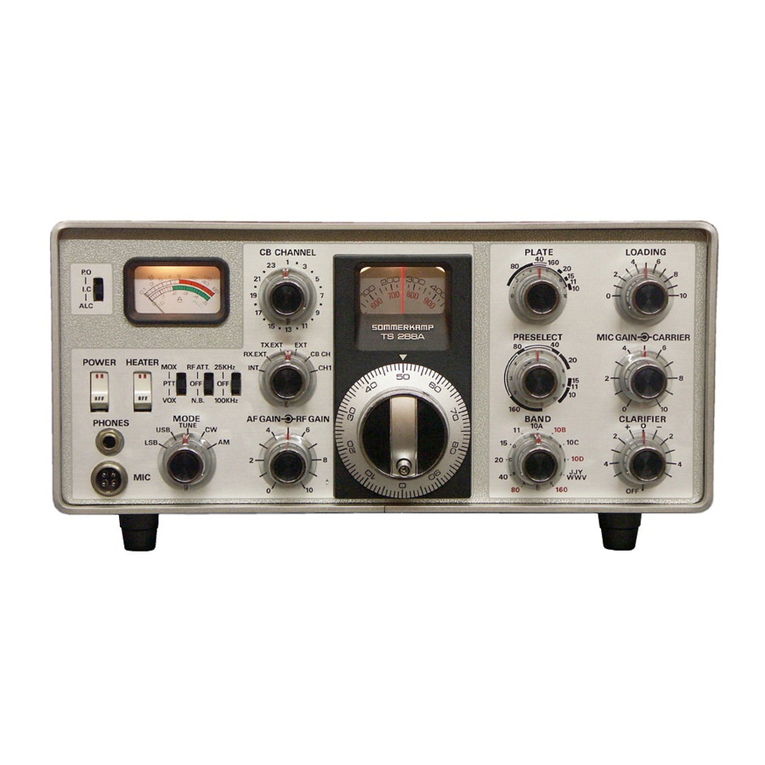
Sommerkamp TS 1608 G User manual
Sommerkamp
Sommerkamp TS 288A User manual

Sommerkamp
Sommerkamp TS 288A User manual

Sommerkamp
Sommerkamp TS-5680 User manual
Popular Transceiver manuals by other brands

Icom
Icom IC-G88-T instructions
Broadcast Tools
Broadcast Tools Telco Sentinel Installation and operation manual
Next Century
Next Century RR4-TR quick start guide
Magnum International
Magnum International Megaforce S45 operating manual
Kenwood
Kenwood TS-520S operating manual

Kenwood
Kenwood TH-415A instruction manual
