Icom IC-F31GT User manual

INSTRUCTION MANUAL
UHF TRANSCEIVERS
iC-f41gt/gs
VHF TRANSCEIVERS
iC-f31gt/gs
iC-f31gt-l
iC-f31gs-l

i
FOREWORD
Thank you for purchasing the IC-F31GT/IC-F31GS, IC-F31GT-L/
IC-F31GS-L, IC-F41GT/IC-F41GS vhf/uhf transceivers.
READ ALL INSTRUCTIONS carefully and completely before using
the transceiver.
SAVE THIS INSTRUCTION MANUAL–This instruction manual con-
tains important operating instructions for the transceiver.
EXPLICIT DEFINITIONS
WORD DEFINITION
RWARNING Personal injury, fire hazard or electric shock
may occur.
CAUTION Equipment damage may occur.
NOTE
If disregarded, inconvenience only. No risk
of personal injury, fire or electric shock.
INSTALLATION NOTES
• When transmitting with a portable radio, hold the radio in a verti-
cal position with its microphone 5 to 10 cm away from your mouth.
Keep the antenna at least 2.5 cm from your head and body.
• If you wear a portable two-way radio on your body, ensure that the
antenna is at least 2.5 cm from your body when transmitting.

PRECAUTIONS
CAUTION! NEVER hold the transceiver so that the antenna
is very close to, or touching exposed parts of the body, especially
the face or eyes, while transmitting. The transceiver will perform
best if the microphone is 5 to 10 cm away from the lips and the
transceiver is vertical.
CAUTION! NEVER operate the transceiver with a headset or
other audio accessories at high volume levels.
CAUTION! NEVER short the terminals of the battery pack.
CAUTION! NEVER use non-Icom battery packs/chargers to
prevent the loss of the transceiver’s good performance and warranty.
DO NOT push [PTT] when not actually desiring to transmit.
DO NOT use or place the transceiver in direct sunlight or in
areas with temperatures below –10°C or above +50°C.
The basic operations, transmission and reception of the transceiver,
are guaranteed within the specified operating temperature range
(depending on version). However, the LCD display may be operate
correctly, or show an indication in the case of long hours of opera-
tion, or after being placed in extremely cold areas.
DO NOT modify the transceiver. The transceiver warranty does
not cover any problems caused by unauthorized modification.
KEEP the transceiver from heavy rain, and NEVER immerse it
in the water. The transceiver construction is water resistant, not
waterproof.
ii
Icom, Icom Inc. and the Icom logo are registered trademarks of Icom Incorpo-
rated (Japan) in Japan, the United States, the United Kingdom, Germany, France,
Spain, Russia and/or other countries.
All other products or brands are registered trademarks or trademarks of their re-
spective holders.

TABLE OF CONTENTS
iii
FOREWORD ..................................................................................i
EXPLICIT DEFINITIONS................................................................i
INSTALLATION NOTES..................................................................i
PRECAUTIONS.............................................................................ii
TABLE OF CONTENTS................................................................ iii
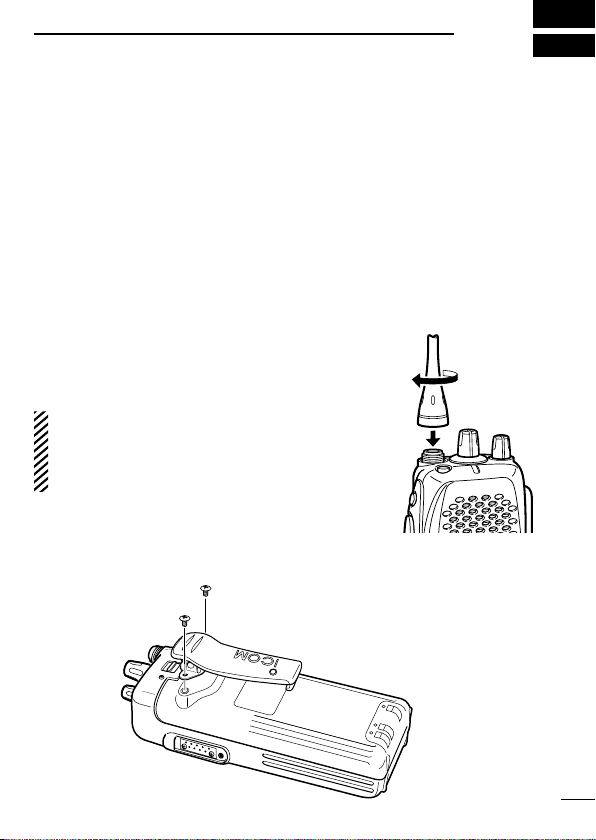
1 ACCESSORIES........................................................................1
n Accessory attachment...........................................................1
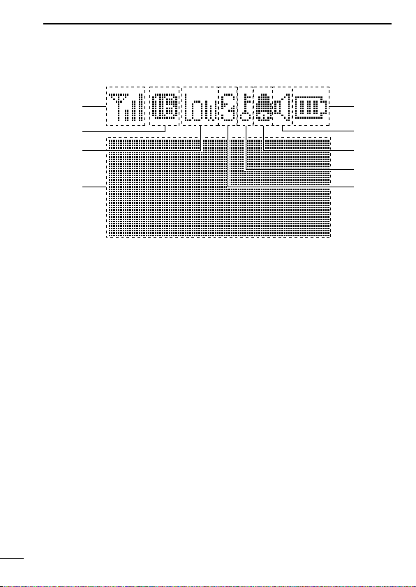
2 PANEL DESCRIPTION ........................................................2–4
n Switches, controls, keys and connectors ..............................2
n Function display ....................................................................4
3 BATTERY PACKS ..............................................................5–10
n Battery pack replacement .....................................................5
n Battery cautions ....................................................................6
n Battery charging....................................................................7
n Charging NOTE.....................................................................9
n Battery case (Option)..........................................................10
4 PROGRAMMABLE FUNCTIONS ....................................11–15
n General ...............................................................................11
5 CONVENTIONAL OPERATION ..........................................16–18
n Receiving and transmitting..................................................16
n Call procedure.....................................................................17
n Tx code channel selection...................................................18
n Manual 5-tone codes ..........................................................18
n Transmitting notes ...............................................................18
6 OTHER FUNCTIONS .............................................................19
n DTMF PAGER/CODE SQUELCH .......................................19
7 OPTIONAL UNIT INSTALLATION .........................................20
n Installation...........................................................................20
8 CLONING ...............................................................................21
n Cloning................................................................................21
9 OPTIONS..........................................................................22–23
10 ABOUT CE.............................................................................24

1
ACCESSORIES
1
nAccessory attachment
DSupplied accessories
The following accessories are supplied. Qty.
• Battery pack*1.............................................................................1
• Flexible antenna*1.......................................................................1
• Belt clip (with screws)..................................................................1
• Jack cover (with screw)*2............................................................1
*1Not supplied depending on the transceiver’s version.
*2See the supplied leaflet for details.
DAntenna
The antenna screws onto the transceiver as
illustrated at right.
✔For IC-F31GT-L/GS-L
The most suitable flexible antenna should
be purchased according to programmed fre-
quency parameters. See page 23 for details.
DBelt clip
Attach the belt clip to the transceiver as illustrated below.
Use the supplied screws only.

PANEL DESCRIPTION
2
2
nSwitches, controls, keys and connectors
q
w
e
r
t
y
u
i
o
!0
!1
Microphone
Speaker
!2
DProgrammable key reference
F0 (Red) P0
F1 (Black) P1
F2 (Black) P2
F3 (Black) P3

2
PANEL DESCRIPTION
3
qANTENNA CONNECTOR
Connects the supplied antenna.
wDEALER-PROGRAMMABLE KEY [F0 (Red)]
eDEALER-PROGRAMMABLE KEY [F1 (Black)]
rPTT SWITCH [PTT]
Push and hold to transmit; release to receive.
tDEALER-PROGRAMMABLE KEYS [F2 (Black)], [F3 (Black)]
Push to select the operating channel. Depends on setting.
yDEALER-PROGRAMMABLE KEYS [P0]/[P1]/[P2]/[P3]
Can each be programmed for one of several functions by your
Icom Dealer.
u10-KEY PAD (10-key versions only)
Used to enter DTMF codes, the operating channel, etc.
iFUNCTION DISPLAY
Displays a variety of information, such as, operating channel
number/names, 5-tone code, remaining battery power, DTMF
numbers, transmit output power setting, Audible indication, etc.
NOTE: The above functions depend on pre-setting.
oMULTI CONNECTOR
Connect optional speaker-microphone, etc.
!0 TRANSMIT/BUSY INDICATOR
Lights red while transmitting; lights green while receiving a sig-
nal, or when the squelch is open.
!1 VOLUME CONTROL [VOL]
Turns power ON and adjusts the audio level.
!2 ROTARY SELECTOR [SEL]
Selects operating channel, or bank. Depends on setting.

PANEL DESCRIPTION
2
4
nFunction display
q
w
e
rt
y
u
i
o
qSIGNAL STRENGTH METER
Indicates relative signal strength level.
wBANK NUMBER INDICATOR
Indicates operating bank (channel group) number.
eLOW POWER INDICATOR
Appears when low output power is selected.
rMULTI-FUNCTION INDICATOR
Indicates operating channel number, channel names, 5-tone
code, etc., according to operating condition.
tSCRAMBLER INDICATOR
Appears while the voice scrambler function is activated.
yKEY LOCK INDICATOR
Appears while the key lock function is turned ON.
uBELL INDICATION
Appears or blinks when a 2/5Tone call is received.
iAUDIBLE INDICATOR
Appears when the monitor function is turned ON. (CTCSS and
DTCS mutes are released.)
oBATTERY INDICATOR
Indicates remaining battery power.

3
BATTERY PACKS
5
nBattery pack replacement
Before replacing the battery pack, the volume control MUST be ro-
tated fully counterclockwise, until a click is heard, to turn the power
OFF.
• Slide the battery release forward, then pull the battery pack up-
ward with the transceiver facing away from you.
Battery release
DBATTERY PACKS
Battery pack Voltage Capacity Battery life*1
BP-208N Battery case for AA
(LR6) ×6 alkaline —*2
BP-210N 7.2 V 1650 mAh 10 hrs.
*1
When the power save function is turned ON, and the operating peri-
ods are calculated under the following conditions;
TX : RX : standby = 5 : 5 : 90
*2The operating period depends on the alkaline batteries used.

3BATTERY PACKS
6
nBattery cautions
• CAUTION! NEVER short terminals (or charging terminals) of the
battery pack. Also, current may flow into nearby metal objects
such as a necklace, so be careful when placing battery packs (or
the transceiver) in handbags, etc.
Simply carrying with or placing near metal objects such as a neck-
lace, etc. may cause shorting. This may damage not only the bat-
tery pack, but also the transceiver.
•
NEVER incinerate used battery packs. Internal battery gas may
cause an explosion.
•
NEVER immerse the battery pack in water. If the battery pack
becomes wet, be sure to wipe it dry BEFORE attaching it to the
transceiver.
• Clean the battery terminals to avoid rust or miss contact.
•
Keep battery contacts clean. It’s a good idea to clean battery ter-
minals once a week.
If your battery pack seems to have no capacity, even after being
charged, completely discharge it by leaving the power ON over-
night. Then, fully charge the battery pack again. If the battery pack
still does not retain a charge (or only very little charge), a new bat-
tery pack must be purchased. (p. 22)

3
BATTERY PACKS
7
nBattery charging
DRapid charging with the BC-119N
The optional BC-119N provides rapid charging of the battery pack.
The followings are additionally required:
• One AD-101 (purchase separately).
• An AC adapter (may be supplied with the BC-119N depending on
version).
BC-119N
+ AD-101
Turn power
OFF.
When using the BC-
119N in a vehicle: If the
charge indicator flashes
orange, the vehicle
battery voltage is low
and charging may not be
performed. Check the
vehicle battery voltage in
this case. If the charge
indicator flashes red,
there may be a problem
with the battery pack (or
charger). Re-insert the
battery pack or contact
your dealer.
(Insert together with
charging adapter.)
Check orientation
for correct charging.
AD-99N— Use Spacer A only!
The adapter (Spacer A) only is required for
charging a battery pack with the IC-F30G
series transceiver.

3BATTERY PACKS
8
DRapid charging with the BC-121N+AD-101
The optional BC-121N allows up to 6 battery packs to be charged
simultaneously. The followings are additionally required.
• Six AD-101.
• An AC adapter (BC-157) or the DC power cable (OPC-656)
Charge indicator
(each indicator functions independently)
Turn power OFF.
AC adapter
(Purchased
separately)
DC power cable (OPC-656)
(Connect with the DC power
supply; 13.8 V/at least 7 A)
DRegular charging with
the BC-137 #11/BC-146
The optional BC-137 #11
or BC-146 provides regu-
lar charging of optional
battery pack with/without
transceiver.
The following is addition-
ally required:
• An optional AC adapter.
(AD-99N is supplied with
BC-137 #11/BC-146)
Turn power OFF.
BC-137 #11
or BC-146
(Insert together
with AD-99N.)
Check orienta-
tion for correct
charging.

3
BATTERY PACKS
9
nCharging NOTE
Prior to using the transceiver for the first time, the battery pack
must be fully charged for optimum life and operation.
• Recommended temperature range for charging:
Between +10°C and +40°C
• Use the supplied charger or optional charger (BC-119N/BC-121N/
BC-144N for rapid charging, BC-137 #11/BC-146 for regular
charging) only. NEVER use other manufacturers’ chargers.
The battery pack contains rechargable battery.
Charge the battery pack before first operating the transceiver, or
when the battery pack becomes exhausted.
If you want to prolong the battery life, the following points should
be observed:
• Avoid over charging. The charging period should be less than 48
hours.
• Use the battery pack until it becomes almost completely ex-
hausted, under normal conditions. We recommend battery charg-
ing after transmitting becomes impossible.
DBattery pack life
When the operating period becomes extremely short, even after
charging the battery pack fully, a new battery pack is needed.

10
3BATTERY PACKS
nBattery case (Option)
When using the optional battery case, install 6 ×AA (LR6) size
alkaline batteries as illustrated below.
CAUTION:
• Use alkaline batteries only.
• When installing batteries, make sure they are all the same
brand, type and capacity. Also, do not mix new and old batter-
ies together.
• Keep battery contacts clean. It’s a good idea to clean battery
terminals once a week.
• Never incinerate used battery cells since internal battery gas
may cause them to rupture.
• Never expose a detached battery case to water. If the battery
case gets wet, be sure to wipe it dry before using it.

4
PROGRAMMABLE FUNCTIONS
11
nGeneral
In the following explanations, programmable function names are
bracketed, the specific switch used to activate the function depends
on programming.
DKEYPAD LOCK FUNCTION
This function locks access to all programmable switches (except
the switch assigned for the lock function).
Push and hold the [Lock] switch for 1 sec. to toggle the lock func-
tion ON and OFF.
• “ ” appears while the lock function is ON.
• This function may be inhibited on some channels.
DPRIORITY CHANNEL
This function is used to select a pre-programmed channel at the
push of a switch.
Push the [Priority A/A (Rewrite)/B] switch to select the priority chan-
nel.
• “Prio A” or “Prio B” appears briefly, then the priority channel is auto-
matically selected.
DSCAN FUNCTION
The scan function allows you to search a pre-programmed group of
channels for signals.
Push the [Scan A/B] switch to start/stop scan.
• Scan pauses on a channel when receiving a signal.
• Depending on programming, a message may appear while scanning.
• “Lockout SCAN” (pre-programmed list SCAN) or “Priority SCAN” can
be pre-programmed.
• When the “Power-save function” is activated, the transceiver checks
all pre-programmed channels then returns to the “Power-save func-
tion” again.

4PROGRAMMABLE FUNCTIONS
12
DHIGH/LOW OUTPUT POWER
This function selects high or low output power for a channel.
Push the [High/Low] switch to change transmit output power be-
tween high, low1 and low2 output power.
• “ ” appears when low1 or low2 output power is selected.
DSCRAMBLER FUNCTION
(An optional UT-109 #02* or UT-110 #02* is required.)
This function provides higher communication security.
UT-109: Non-rolling type. 32 code numbers are available.
UT-110: Rolling type. 1020 (4 groups ×255) code numbers are
available.
Push the [Scrambler] switch to toggle the function ON and OFF.
*
NEVER use #01 Low AF level versions of the scrambler unit, as
they are not compatible.

4
PROGRAMMABLE FUNCTIONS
13
DMONITOR AUDIBLE FUNCTION
The monitor function allows you to open the transceiver’s squelch
manually to check whether a channel is busy or not. The trans-
ceiver has 2 conditions for receive standby:
All signals are received.
Audible condition:
This condition mutes audio ONLY when
no carrier is present.You can receive (or
monitor) any signals on a channel.
• Push and hold the [Moni (Audi)], switch
to select the audible condition.
Any audio mute functions are cancelled
while pushing the [Moni (Audi)] switch.
Only signals containing the
proper tone are received.
Inaudible condition:
This condition mutes ALL signals ex-
cept those directed to you. Therefore
you should check a channel’s condition
(busy or not) with the monitor function
before transmitting.
• Push the [Moni (Audi)], switch momen-
tarily to select the inaudible condition.
DTALK AROUND
The talk around function changes duplex channels to simplex chan-
nels.
• Duplex allows you to contact your base station, repeaters, etc.
• Simplex allows you to contact other portable transceivers directly
(portable-to-portable contact).
Push the [Talk Around] switch to toggle the function ON and OFF.

4PROGRAMMABLE FUNCTIONS
14
DDTMF TRANSMISSION
This function allows you to send a pre-programmed DTMF code to
control a repeater, open another transceiver’s squelch, etc.
Manual transmission:
Push desired digit keys in sequence while pushing [PTT].
• Pushing [PTT] may not be necessary depending on programming.
Automatic pre-programmed transmission:
qPush the [DTMF Autodial] switch to select DTMF autodial mode,
then push [CH Up] or [CH Down] to select the desired channel.
wPush the [DTMF Autodial] switch to send a DTMF code.
D DTMF RE-DIAL FUNCTION
This function allows you to transmit the last-used DTMF code at
the push of a key.
Push the [Re-dial] switch momentarily to activate the function.
• The previously transmitted DTMF code is automatically transmitted.
• If no code has been transmitted since turning the power ON, this func-
tion does not activate.
DEMERGENCY FUNCTION
The emergency function allows you to send an emergency signal
quickly and easily to your base station, etc. in case of emergency.
Push and hold the [Emergency Single/Repeat] switch for 1 sec. to
activate the emergency function.
• The transceiver selects a pre-programmed channel, then sends an
emergency signal to your base station.
• The pre-programmed channel remains selected until a control signal
is received from the base station, or power is turned OFF.
• The emergency call is repeatedly transmitted at pre-programmed in-
tervals.

4
PROGRAMMABLE FUNCTIONS
15
DDISPLAY LIGHTING
The function display has 3 backlight conditions.
ON : Backlight stays ON continuously.
OFF : No backlight.
AUTO : When any key is pushed, the backlight turns ON for 5
sec. automatically.

5CONVENTIONAL OPERATION
16
nReceiving and transmitting
NOTE: Transmitting without an antenna may damage the trans-
ceiver. See p. 1 for antenna attachment.
Turn power ON as described on p. 3.
Receiving:
qPush [CH Up]/[CH Down], or rotate [SEL] to select a channel.
wListen for a transmission and adjust [VOL] to a comfortable lis-
tening level.
• When no transmission is heard, push and hold monitor while ad-
justing [VOL] (your transceiver may not be programmed with the
monitor function).
The transceiver is now set to receive desired calls on the selected
channel.
Transmitting:
Wait for the channel to become clear to avoid interference.
qWhile pushing and holding [PTT], speak into the microphone at
a normal voice level.
• When a tone signalling system is used, the call procedure de-
scribed at right may be necessary.
wRelease [PTT] to return to receive.
IMPORTANT: To maximize the readability of your transmitted sig-
nal, pause a few seconds. After pushing [PTT], hold
the microphone 5 to 10 cm from your mouth and
speak at a normal voice level.
Other manuals for IC-F31GT
1
This manual suits for next models
6
Table of contents
Other Icom Transceiver manuals

Icom
Icom IC-Q7A User manual

Icom
Icom IC-V10MR User manual

Icom
Icom IC-720A User manual

Icom
Icom IC-A2 User manual

Icom
Icom ID-31E PLUS Installation guide

Icom
Icom IC-F15 User manual

Icom
Icom IC-2340H User manual

Icom
Icom IC-F5060 Series User manual

Icom
Icom IC-F1000 series User manual

Icom
Icom IC-M323 User manual
Popular Transceiver manuals by other brands

Kenwood
Kenwood TH-28A instruction manual

Micom
Micom RM125 owner's guide

MDS
MDS MDS 4710 Series Installation and operation guide

City Theatrical
City Theatrical Multiverse Vero 7400-5903 user manual

Thrane&Thrane
Thrane&Thrane TT-3020B Technical reference manual

ELANsat Tech
ELANsat Tech DRF-TR001 user manual