XIEGU X5105 User manual

XIEGU COMMUNICATION
X5105
HF+50MHz Portable HF Transceiver
Instruction Manual V1.0.03
Chongqing Xiegu Technology Co.,Ltd.
www.cqxiegu.com

2
Important reminder:
Before operating the equipment, please
read our operating manual carefully and
keep the manual, so as not to lose.
Security considerations:
Do not use equipment during a lightning storm.
Damp-proof!
Don't illegal operations!
Note RF high-voltage of antenna connector!
Features:
l3.6 inch LCD screen
lBuilt in 5000mAh large capacity battery
pack
lBuilt in ATU
lCovers all modes of HF, 50MHz band
(SSB/CW/AM/FM/RTTY/PSK)
lIF signal output
lBuilt in AF-DSP digital noise reduction
processor
lEquipped with trestle for desktop
operation
lVery small in size and ultra portable
Packing list:
Qty
①X5105...... ...... ...... ...... ...... ...... ...... 1
②Power supply cable........... ........... ......1
③Hand microphone.............. ........... .....1
④USB Cable........... ........... ........... .........1
⑤Service card................. ........... ........... 1
①
②
④
③
⑤

3
Introduce
The X5105 is an ultra-portable multimode HF transceiver. 3.6 "super large LCD display
screen with rich content information. Built-in 3800mAh high-capacity battery pack can
provide 6 to 8 hours of use time for outdoor use, built-in highly efficient automatic
antenna tuner (ATU), so you no longer worry about the antenna problem, you can
quickly deploy your field shortwave communication station. X5105 covers HF, 50MHz
band full mode.
X5105 has many advanced functions of large base stations. VFOA/B mode, split
frequency transceiver function, RIT receive fine tuning, NB noise suppressor, AGC
speed selection, NR digital noise reduction, number NOTCH, built-in automatic
telegraph keys, built-in efficient automatic antenna tuner, CW trainer, large capacity
battery pack, and computer-aided control functions.
X5105 has a small size (about 168 * 93 * 47mm, without protrusions), light body
(about 0.94kg). It provides up to 5W of RF power over the full frequency range. It
operates normally from 9 to 15V DC; its low standby current provides longer battery
life, it has intelligent battery management.

4
1 X5105 Specifications
Basic Specifications
Frequency range:
Receive: 500kHz-30MHz 50MHz-54MHz
Transmitting: 160 meters -6 meters (Amateur band only)
Operating mode: A1A(CW),A3E(AM),J3E(USB/LSB),F3E(FM)
minimum frequency stepping: 1Hz
Antenna impedance: 50Ω
Operating temperature range: -10℃~ +60℃
Frequency stability: after turn on the radio 1-60 minutes is + 4ppm, @25℃:1ppm/hour
supply voltage: normal: 13.8VDC + 15%, negative grounding
Operating voltage: 9.0-15.0VDC, negative grounding
Current consumption: receive: 500mA@ Max transmit: 2.5A@ Max
Battery capacity: 3800mAh @12V
Dimensions: 168*93*47mm[does not include protrusion]
Weight: 0.94Kg[host only]
Transmitter parameters
Transmitter power:5W(SSB/CW/FM),1.5W(AM carrier),@13.8VDC
Modulation mode: SSB balanced modulation/AM low level amplitude modulation/FM
Variable reactance frequency modulation
FM Maximum frequency swing: ±5kHz
spur reduction: -45dB
Carrier suppression: >40dB
Sideband spurious: >50dB
SSB frequency response: 400Hz-2800Hz(-6dB)
Microphone impedance: 200-10k(conventional 600Ω)

5
Receiving parameters
Circuit type: double frequency conversion superheterodyne + audio DSP
IF frequency: first IF: 70.455MHz second IF: 10.695MHz third IF: 455kHz(NFM)
Sensitivity
(PRE=on,ATT=off,NB=off,NR=off,SSB/CW/AM = 10dB S/N,FM = 12dB SINAD)
Image rejection: 70dB
If Rejection: 60dB
Selectivity: SSB:-6dB:2.4kHz/-60dB:4.6kHz
CW:-6dB:500Hz/-60dB:2000Hz
AM:-6dB:6.0kHz/-60dB:25.0kHz
FM:-6dB:12.0kHz/-60dB:25.0kHz
Audio output: 0.6W (8Ω,≤10% THD)
Audio output impedance: 4 – 16Ω
SSB/CW AM FM
1MHz-1.8MHz
0.35uV 10uV /
1.8MHz-28MHz
0.25uV 2uV /
28MHz-30MHz
0.25uV 2uV 0.35uV
50MHz-54MHz
0.25uV 2uV 0.35uV

6
Packing List
Item Quantity
X5105 1pcs
Mic 1pcs
power cable 1pcs
Data cable 1pcs
Instructions 1pcs
Certificate 1pcs
warranty card 1pcs
==================================================
Optional accessories
Item Description
CE-19 ACC Wiring expansion card
XPA125 120W PA and ATU integrated machine

7
Interface definition

8
Charging and maintenance of internal battery
X5105 has a built-in 3800mAh battery pack. When the external power supply is not
connected, the battery pack supplies power to the X5105, when the X5105 is connected
with an external power supply, the circuit inside the machine automatically switches to
the external power supply.
Charging method:
1In the menu-7, select [CHG], select “CHG ON”, start charging function.
2select “Charger ON”, Start boot-strap charging function.
3Select “Charger OFF” Shut down boot-strap charging function. If it is power off, then
the default is start boot-strap charging function.
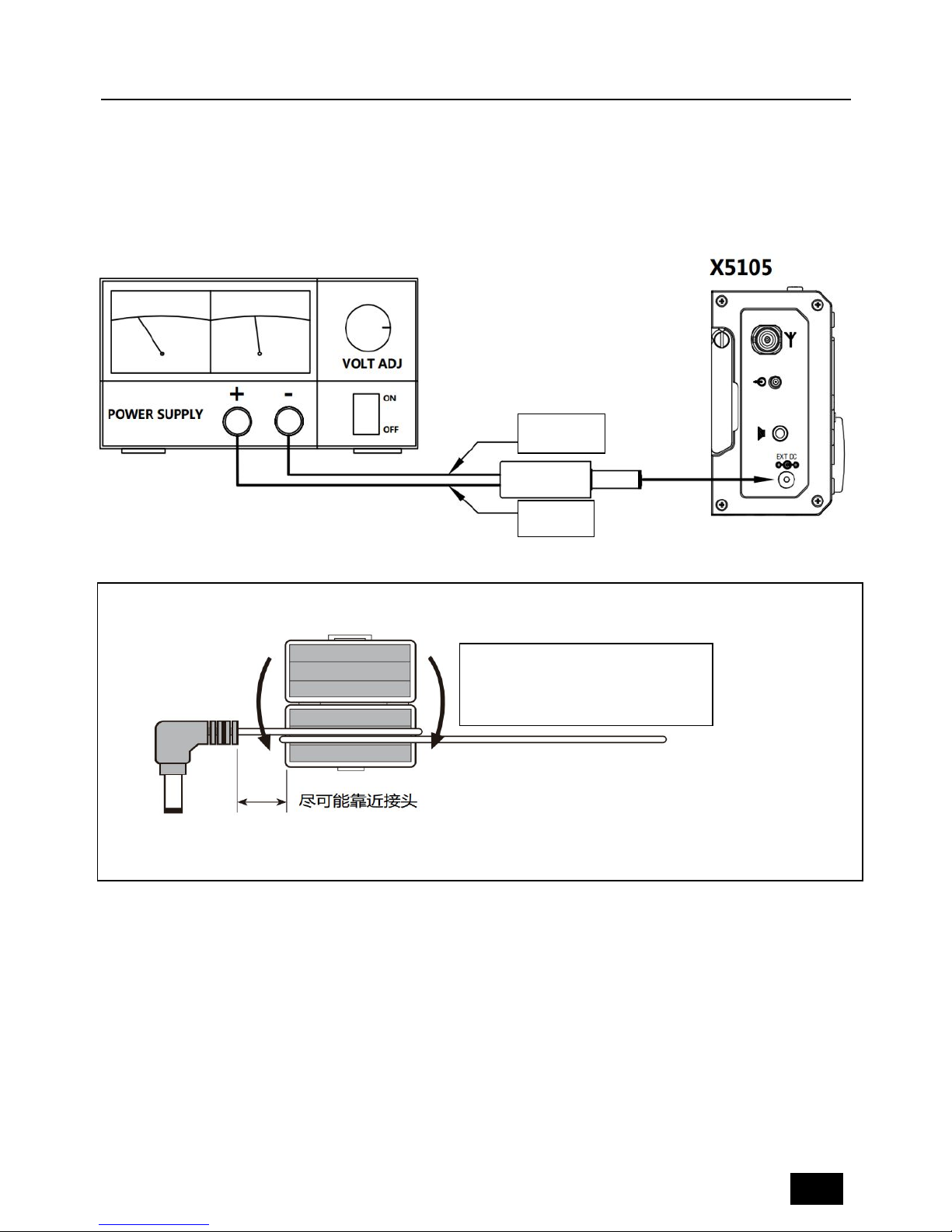
4The external power supply voltage is set between 13.5V-15.0V and the power supply
is connected to the X5105 external power supply.
The host will automatically start charging.
5The maximum charge time is about 12~15 hours. When the battery is full, the
charging will stop automatically.
When the battery is powered for X5105, when the battery power is about to run out, the
power indication sign on the upper right corner of the screen is displayed as . At this
point, the X5105 should be charged or switched to an external power supply. During the
charging process, the casing of the machine has a slight fever.
Normally, the lifetime of the internal battery is about 3 years. When there is a significant
drop in capacity or charging failure, contact the dealer to replace the battery (outside
the warranty period, you will be charged for a fee).
When using an external power supply, do not exceed the rated voltage of the device,
otherwise it will cause damage to the device.
Please turn off the power immediately when the machine shell is very hot near the
battery, and put the equipment in a safe and ventilated place. After confirming the
safety situation, please contact us for proper handling.

9
External power supply connection
External DC power supply output voltage: 13.8;electric current load capacity:3A
Cable connection method:
white wire connect "+", shielded wire connect "-".
EMC magnetic ring installation method:As shown;
Shielded
white
The headphone cable Loop two Loop
around the magnetic ring .

10
2 Description of equipment
2.1 Front panel button function
①Power button
Press this button for a second to turn on or turn off the radio.
②Mode button
With this key, you can change the mode of operation and will cycle in the following mode:
[LSB-USB-CW-CWR-NFM-AM]
③PRE/ATT button
With this key, the preamplifier or pre attenuator will be turned on or be turn off in the
following states: [PRE=ON--ATT=ON--PRE/ATT=OFF]
④RIT button
With this key, the receive frequency adjustment function is turned on.
⑤NB button
With this key to turn on or turn off the NB function.
⑥MENU button
With this key, you can switch the current display of the multi-function menu.
⑦-⑩Multifunctional menu button
Press these four buttons to turn on or off the corresponding function displayed on the
menu area on the current screen.
○
11 Major tuning knob
The main tuning knob of X5105, can be used either for frequency regulation or set the
parameters.
○
12 ATU button

11
When the key is pressed for a short time, the automatic antenna tuner will be connected
to the antenna port, by pressing this button for a long time, the automatic antenna tuner
will be started.
○
13 Po button
With this key, and with the main tuning knob, the power of the transmitter can be
adjusted. The range of adjustment is from 0.5W-5W, stepping for 0.5W.
○
14 A/B button
With this key, you will switch between VFOA/VFOB.
○
15 <button
With this key, the current frequency step carries one bit to the left.
○
16 >button
With this key, the current frequency step carries one bit to the right.
○
17 V/M button
With this key, you can switch between VFO mode and MEMO mode.
○
18 Up button
With this key, X5105 can be switched to higher frequency bands.
○
19 DN button
With this key, X5105 can be switched to lower frequency bands.
○
20 -button
With this key, you can reduce current volume.
○
21 +button
With this key, you can increase current volume.
○
22 PTT button
Press and hold this button, X5105 will go into the transmit state.
○
23 LOCK button
If you press this button for a short time, you will lock all buttons and knobs on the panel;
By pressing this button for a long time, you can set the backlight on / off.
Status indicator
A [T/R] B [DATA]
C [LINK]
Transmit/Receive
switch indication
Data
indication
Peripheral indicator
light
Indicator color description:
A T/R indicator
When the X5105 is in receiving mode, the indicator light is green.
When the X5105 is in transmitting mode, the indicator light is red.

12
B DATA indicator
When the data signal or channel are busy, the indicator light flashes.
C LINK indicator
When the host is connected with the external equipment, the indicator light will shine.
Function menu corresponding to 4 multi-function buttons below screen.
1.
A=B SPL NR NTH
Copy VFOA to the
background
Split On/Off Digital noise
reduction
number Notch
2.
AGC FIL SRM SWR
Automatic gain
control selection
Filter selection Scan receiving mode
SWR scanning
3.
M > V MW MC TAG
Save the VFO
frequency on the
channel
Store current
channel
Clear current
channel
Channel information
/ custom
characters(Press this
button for a long
time to enter the
editor)
4.
BK KEY KSP -
CW insert function
on / off
Key manual /
automatic mode
selection
Automatic key rate
selection
-

13
5.
RE1 RE2 RE3 CSN
Set CW message
1(Press this button
for a long time to
enter the message
editing)
Set CW message
2(Press this button
for a long time to
enter the message
editing)
Set CW message
3(Press this button
for a long time to
enter the message
editing)
Power on display
call sign
editing(Press this
button for a long
time to enter the
editor
)
6.
SQL CMP MTR VLT
Squelch function Speech compression
Display switch of
multi-function table
Power / voltage
display switching
7.
CHG MSL IFO VER
Charging switch Built-in / external
MIC selection
IF output switch Firmware version
display
8
MDN -CAR -AFC ------
Digital MODEM Carrier Tracking
(MDN=ON)frequency tracking
(MDN=ON)
9 AFF -HPF -LPF SPK
Digital audio filter high-pass filter lower-pass filter Speaker / headphone
mode selection
Screen display information

14
2.2 Left panel interface function
①Left bracket
Rotate the bracket when using it, when after using it, take it back to the side shield.
②Antenna interface
Connect the antenna to the 50 ohm coaxial cable with the BNC connector.
③IF signal output port
The first IF signal is output for use by the XDT1.
*XDT1 is a data terminal equipment of Xiegu.
④External speaker / earphone interface
This interface is 3.5mm stereo socket (3 line), it can connect external speaker (impedance
4-16).
Before inserting the headset into the interface, be sure to select earphone mode first so
as to avoid damage to your hearing and headset.
⑤DC power interface
The external DC power input interface, it uses the standard power cord to connect the
external stable DC power to this interface. The external DC power supply must be able to
provide the power output of the 13.8V@3A. The interface can also be used to charge for
internal battery.
2.3 Right panel interface function

15
①ACC interface
The interface is a 8PIN micro DIN interface, it can be used for external power amplifier
connection, PTT control, band signal transmission, it can also be used to communicate
with the computer for PSK communication when the audio signal input / output.
②KEY interface
The interface is 3.5mm stereo interface, which can be used to connect manual /
automatic telegraph keys.
Key connection is shown in this figure:
Manual key, you need to "drop"
And "click" connected together
③ATU interface
The interface is a 3.5mm interface (3 lines) that can be used to control external power
amplifiers with antenna tuning.
④CIV interface
The interface is a 3.5mm interface (3 wire) which used for the connection of the
computer aided control system or firmware update.
⑤Right bracket
Rotate the bracket when using it, when after using it, take it back to the side shield.
⑥MIC (microphone) interface
The interface can be used for microphone connections.
2.4 Handheld microphone function

16
1. LOCK button, you can lock the host button and the mouse button via this button, and
press it again to unlock.
2. PTT button, transmitting control button.
3. Move up/down, Increase and decrease of frequency.
4. Receiving / Transmitting indicator light, microphone operated indicator light.
5. Digital key
6. FIL button, built in filter selection.
7. MODE button, selection of host operating mode.
8. Function indicator lamp, No indication.
9. Function button, F1/F2 custom settings button.
10.MW button, store operation.
11.V/M button, frequency / channel switching.
12.XFC button, No function.
13.CALL button, press this button for a long time to start the automatic antenna tuning in
the host.
3Operation
3.1 Turn on / off transceiver
1. Turn on the transceiver: just press for a long time
2. Turn off the transceiver: in the boot state, press the key for a long time.
Press the button of the switch to delay one second, in order to prevent the misoperation
of the switch key.
Forced reset: When the host system is in a halted state, such as the key is not
responding, or can not exit the transmit state and the key is not responding, long press
the power button and hold for more than 8 seconds, will force reset the MCU and shut
down.
3.2 Battery / voltage display
1. When the battery is powered by the built-in battery, the remaining battery power of
the current battery will be displayed in the upper right corner of the display.
2. When using an external power supply, after switching to the [VLT] Page 6 menu, this
location shows the voltage level of the external DC power currently connected to the
transceiver.

17
If you have not used the X5105 transceiver for more than 20 days, we recommend
that you plug it in with an external power source and charge the device until the
display is done. For details, please refer to [Charge] section.
3.3 Operating frequency band selection
The frequency range of X5105 covers 1~54MHz. The amateur frequencies in this range
are divided into multiple frequency bands and can be switched in a number of different
ways. You can complete the equipment operation according to the operation instructions
in this section.
Operation method: press DN or UP key to switch to the next or last operation band
respectively.
3.5MHz 7.0MHz 10MHz 14MHz
18MHz
21MHz
24MHz
1.8MHz
28MHz
5.2MHz
50MHz
A. The opening of the 5MHz frequency band is based on the regulations of the country
(or region) where it is located.
B. Different versions of the machine have different frequency divisions, depending on
their country (or region) regulations.
C. VFO-A and VFO-B are two separate VFO modes, which can be set to different working
conditions, please refer to the [VFO settings].
3.4 Work mode selection
Press the [MODE] button to switch between all modes in a fixed order.
USB CWR
LSB
AM
CW
FM
*VFO-A and VFO-B can be set to different operating modes in the same frequency
band, thus realizing the different operation modes of "voice /CW".

18
3.5 Adjust the volume
Adjust the output volume according to the volume plus and minus buttons.
When using the AF- IN/OUT port of the ACC interface, please adjusting the volume level
in the system menu.
3.6 Regulated transmit power
Press the [Po] transmit power setting button, you can set the transmit power.
A. Press the [Po] button to enter the power setting state, the screen will display the Po
power setting number.
B. Rotate the big knob, set the power, step 0.5W.
When you do not understand the current state of the antenna, minimize the set transmit
power value for the first time you use the X5105 transceiver.
3.7 Use the host PTT button
X5105 comes with a PTT button, you can start the transceiver's transmission through this
button.
Operation method:
A. Press this button to start the transmitting function.
B. Speaking into the built-in MIC hole, can be completed communications.

19
3.8 Set operating frequency
There are two ways to set the X5105 operating frequency, use the big knob to set the
frequency, or use the multi-function mic to set the frequency.
Operation method:
A. Use large knob to set frequency
Press the button [<] or [>], move the cursor of the frequency bit to the left or to the
right, select the frequency of the desired step.
Rotating frequency knob sets the frequency of the current step.
B. Use a multi-function microphone for frequency setting
Press the [F-INP ENT] button on the cursor, and the X5105 enters the frequency setting.
The cursor appears on the left of the frequency display bit.
Enter the desired frequency value in turn, and then press [F-INP ENT] button again to
complete the frequency setting.
For example, set the current frequency to 51.050000MHz, and press the order as
follows:
First, press the [F-INP ENT] button.
Please press the 51.050000 numeric key in turn.
Once again press the [F-INP ENT] button to complete the settings.
3.9 Start the ATU (automatic antenna tuner) into the tuning function
X5105 transceiver built-in an efficient automatic antenna tuner, which can help you easily
complete the erection and debugging of the antenna.
Press the [ATU] button shortly to access the built-in tuner and the "TUNE" logo appears
on the top of the screen.
Press the [ATU] button for a long time, it will start the ATU auto tuning function. When
the tuning is complete, the host will automatically return to the receiving state.
3.10 RIT (receive frequency trimming)
Relative to the set frequency, the RIT function can set the offset value of the actual
In actual operation, if the [HI-SWR] icon flashes on
the screen, the tuning fails, and the SWR is large
and needs to be tuned again.

20
receiving frequency of the maximum ±1.5kHz.
Operation method:
A. Press [RIT] button to start RIT function.
B. The rotating knob can change the receiver frequency in the range of ±5kHz. The
screen has the corresponding area to display the frequency change value.
C. If you want to clear the RIT offset, press [RIT] button for about 2 seconds, in the
system prompt tone "beep" sound, the value of RIT settings will be cleared.
If the frequency offset range more you want, you can use split frequency transceiver
mode. Please refer to the VFO instructions for details.
3.11 Automatic gain control (AGC)
By adjusting the appropriate AGC automatic gain control speed, the receiver can achieve
the best effect. Operation method:
A. Switch to the second page menu, press [AGC] function button shortly.
B. The AGC function will be selected in the following order:
When you select "AGC-AUTO", the CW mode is actually "AGC-FAST", in voice mode is
"AGC-SLOW."
If AGC-OFF is selected, the AGC system is turned off and the display of the S table is
stopped.
3.12 Preamplifier / preamplifier (PRE/ATT)
Pre amplifier (PRE) and pre attenuator (ATT) can improve the receiver's listening effect.
When the signal is weak, the preamplifier can be switched on to increase the signal
strength. When the signal is strong, the preamplifier can be switched on to reduce the
signal strength.
Of course, you can also choose to turn off the circuit unit so that the signal will by pass.
Operation method:
A. Press the [PRE/ATT] button to start the function.
B. The switching sequence will follow the following loop:
In the low frequency waves (less than 10MHz) operation, the preamplifier can be closed,
then let signal in by-pass state, it will be more conducive to improve the receiving effect,
AGC
-
FAST
AGC-
SLOW
AGC
-
AUTO
AGC-
OFF
ATT
PRE
OFF
Other manuals for X5105
7
Table of contents
Other XIEGU Transceiver manuals