Icom ID-800H User manual

INSTRUCTION MANUAL
ID-800H
VHF/UHF DIGITAL TRANSCEIVER
This device complies with Part 15 of the FCC rules. Operation is sub-
ject to the following two conditions: (1) This device may not cause
harmful interference, and (2) this device must accept any interference
received, including interference that may cause undesired operation.
ID-800H_1.qxd 2007.06.14 3:08 PM Page a

i
Thank you for purchasing this Icom product. The ID-800H
VHF
/
UHF DIGITAL TRANSCEIVER
is designed and built with Icom’s
state of the art technology and craftsmanship. With proper care,
this product should provide you with years of trouble-free oper-
ation.
We want to take a couple of moments of your time to thank
you for making your ID-800H your radio of choice, and hope
you agree with Icom’s philosophy of “technology first.” Many
hours of research and development went into the design of
your ID-800H.
DD
FEATURES
❍DV mode (Digital voice + low-speed data
communication) available
– GPS receiver connection
– Text message and call sign exchange
❍Switchable VHF and UHF transceiver
❍55 W*—high transmit output power
*VHF band; 50 W for UHF band
❍Detachable controller for flexible installation
❍Large tuning dial and band switch button
❍Selectable backlit color from amber, green
and yellow
❍Total 512 memory channels with bank link
scan
❍Remote control microphone standard
FOREWORD
ID-800H_1.qxd 2007.06.14 3:08 PM Page i

ii
IMPORTANT
READ ALL INSTRUCTIONS carefully and completely
before using the transceiver.
SAVE THIS INSTRUCTION MANUAL— This in-
struction manual contains important operating instructions for
the ID-800H.
EXPLICIT DEFINITIONS
WORD DEFINITION
RWARNING!
CAUTION
NOTE
Personal injury, fire hazard or electric shock
may occur.
Equipment damage may occur.
Recommended for optimum use. No risk of
personal injury, fire or electric shock.
Icom, Icom Inc. and the logo are registered trademarks of Icom
Incorporated (Japan) in the United States, the United Kingdom, Ger-
many, France, Spain, Russia and/or other countries.
ID-800H_1.qxd 2007.06.14 3:08 PM Page ii

iii
RWARNING RF EXPOSURE! This device emits Radio
Frequency (RF) energy. Extreme caution should be observed when
operating this device. If you have any questions regarding RF expo-
sure and safety standards please refer to the Federal Communica-
tions Commission Office of Engineering and Technology’s report on
Evaluating Compliance with FCC Guidelines for Human Radio fre-
quency Electromagnetic Fields (OET Bulletin 65).
RWARNING! NEVER connect the transceiver to an AC out-
let. This may pose a fire hazard or result in an electric shock.
RWARNING! NEVER operate the transceiver while driving a
vehicle. Safe driving requires your full attention—anything less may
result in an accident.
NEVER connect the transceiver to a power source of more than
16 V DC. This will damage the transceiver.
NEVER connect the transceiver to a power source using reverse
polarity. This will damage the transceiver.
NEVER cut the DC power cable between the DC plug and fuse
holder. If an incorrect connection is made after cutting, the transceiver
may be damaged.
NEVER expose the transceiver to rain, snow or any liquids. The
transceiver may be damaged.
NEVER operate or touch the transceiver with wet hands. This may
result in an electric shock or damage the transceiver.
NEVER place the transceiver where normal operation of the vehi-
cle may be hindered or where it could cause bodily injury.
NEVER let objects impede the operation of the cooling fan on the
rear panel.
DO NOT push the PTT when not actually desiring to transmit.
DO NOT allow children to play with any radio equipment contain-
ing a transmitter.
During mobile operation, DO NOT operate the transceiver with-
out running the vehicle’s engine. When the transceiver’s power is ON
and your vehicle’s engine is OFF, the vehicle’s battery will soon be-
come exhausted.
AVOID using or placing the transceiver in direct sunlight or in
areas with temperatures below –10°C (+14°F) or above +60°C
(+140°F).
BE CAREFUL! The transceiver will become hot when operat-
ing it continuously for long periods.
AVOID setting the transceiver in a place without adequate venti-
lation. Heat dissipation may be affected, and the transceiver may be
damaged.
AVOID the use of chemical agents such as benzine or alcohol
when cleaning, as they can damage the transceiver’s surfaces.
USE Icom microphones only (supplied or optional). Other manu-
facturer’s microphones have different pin assignments and may dam-
age the transceiver if attached.
For U.S.A. only
CAUTION: Changes or modifications to this device, not ex-
pressly approved by Icom Inc., could void your authority to
operate this device under FCC regulations.
PRECAUTIONS
ID-800H_1.qxd 2007.06.14 3:08 PM Page iii

iv
SUPPLIED ACCESSORIES
qDC power cable (3 m) ………………………………………1
wMobile mounting bracket …………………………………1
eMicrophone (HM-133)* ……………………………………1
rFuse (20 A) …………………………………………………1
tMounting screws, nuts and washers …………………1 set
yMicrophone hanger …………………………………………1
uSeparation cable†(3.5 m; 11.5 ft) …………………………1
*HM-118N
HAND MICROPHONE
supplied versions are also available.
†A ferrite core is adapted for the USA version.
qw
ert
yu
ID-800H_1.qxd 2007.06.14 3:08 PM Page iv

v
FOREWORD .............................................................................. i
IMPORTANT ............................................................................. ii
EXPLICIT DEFINITIONS .......................................................... ii
PRECAUTIONS ....................................................................... iii
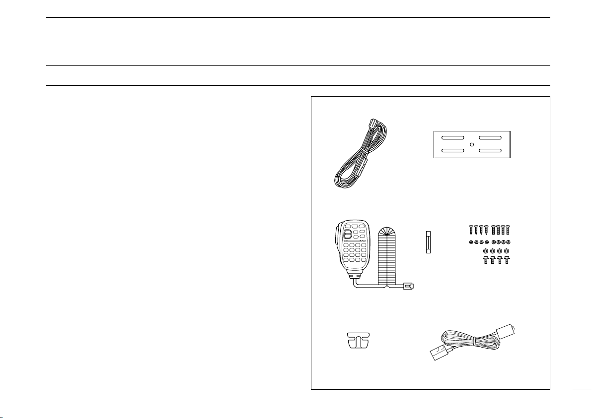
SUPPLIED ACCESSORIES ..................................................... iv
TABLE OF CONTENTS ............................................................ v
QUICK REFERENCE GUIDE ............................................... I–X
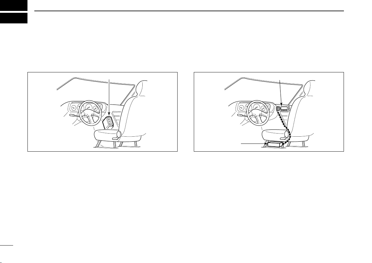
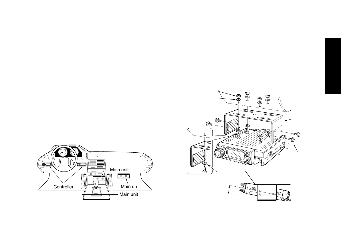
■Installation .......................................................................... I
■Your first contact ............................................................. VII
■Repeater operation .......................................................... IX
■Programming memory channels ....................................... X
1 PANEL DESCRIPTION .................................................. 1–10
■Front panel—controller ..................................................... 1
■Function display ................................................................ 3
■Rear panel ........................................................................ 5
■Microphone (HM-133) ....................................................... 7
■Microphone keypad .......................................................... 8
■Optional microphone (HM-118N) ..................................... 10
2 SETTING A FREQUENCY ........................................... 11–14
■Preparation ...................................................................... 11
■Using the tuning dial ....................................................... 12
■Using the [Y]/[Z] keys .................................................... 12
■Using the keypad ............................................................ 12
■Tuning step selection ...................................................... 13
■Lock functions ................................................................. 14
3 BASIC OPERATION .................................................... 15–19
■Mode selection ................................................................ 15
■Receiving ........................................................................ 16
■Monitor function .............................................................. 16
■Squelch attenuator .......................................................... 17
■Audio mute function ........................................................ 18
■Transmitting .................................................................... 18
■Selecting output power ................................................... 19
■One-touch PTT function .................................................. 19
4 REPEATER OPERATION ............................................ 20–27
■General ........................................................................... 20
■Accessing a repeater ...................................................... 21
■Subaudible tones (Encoder function)............................... 23
■Offset frequency ............................................................. 26
■Auto repeater (USA version only) ................................... 27
5 MEMORY OPERATION ............................................... 28–39
■General description ......................................................... 28
■Memory channel selection .............................................. 28
■Programming a memory channel .................................... 29
■Copying memory contents .............................................. 31
■Programming channel names ........................................ 33
■Memory clearing ............................................................. 36
■Memory bank selection ................................................... 37
■Memory bank setting ...................................................... 38
■Transferring bank contents ............................................. 39
6 CALL CHANNEL OPERATION ................................... 40–41
■Call channel selection ..................................................... 40
■Call channel transferring ................................................. 40
■Programming a call channel ........................................... 41
7 SCAN OPERATION ..................................................... 42–48
■Scan types ...................................................................... 42
■Scan start/stop ................................................................ 43
■Scan edges programming ............................................... 45
TABLE OF CONTENTS
ID-800H_1.qxd 2007.06.14 3:08 PM Page v

vi
■Skip channel setting ........................................................ 47
■Scan resume condition ................................................... 48
8 PRIORITY WATCH ....................................................... 49–50
■Priority watch types ......................................................... 49
■Priority watch operation .................................................. 50
9 DTMF MEMORY ENCODER ........................................ 51–54
■Programming a DTMF code ........................................... 51
■Transmitting a DTMF code ............................................. 53
■DTMF speed ................................................................... 54
10POCKET BEEP AND TONE SQUELCH ...................... 55–59
■Pocket beep operation .................................................... 55
■Tone/DTCS squelch operation ........................................ 58
■Tone scan ....................................................................... 59
11DIGITAL MODE OPERATION ...................................... 60–91
■Digital mode operation .................................................... 60
■Call sign programming .................................................... 60
■Digital voice mode operation .......................................... 65
■About D-STAR system .................................................... 68
■Digital repeater operation ............................................... 69
■Received call sign ........................................................... 75
■Copying the call sign ....................................................... 77
■Message items ................................................................ 80
■Break-in communication ................................................. 84
■Pocket beep operation .................................................... 85
■Digital squelch function ................................................... 86
■EMR communication ....................................................... 87
■Low-speed data communication ..................................... 88
■GPS operation ................................................................ 89
12OTHER FUNCTIONS ................................................. 92–118
■Set mode ........................................................................ 92
■Initial set mode .............................................................. 104
■Weather channel operation (USA version only) ............ 111
■Packet operation ........................................................... 112
■Microphone keys ........................................................... 115
■Partial reset ................................................................... 116
■All reset ......................................................................... 116
■Data cloning .................................................................. 117
13MAINTENANCE ....................................................... 119–120
■Troubleshooting ............................................................ 119
■Fuse replacement ......................................................... 120
14SPECIFICATIONS AND OPTIONS .......................... 121–122
■Specifications ................................................................ 121
■Options ......................................................................... 122
15MODE ARRANGEMENT ......................................... 123–126
1
2
3
4
5
6
7
8
9
10
11
12
13
14
15
ID-800H_1.qxd 2007.06.14 3:08 PM Page vi

I
QUICK REFERENCE GUIDE
■Installation
DInstallation methods
• Single body installation
• The supplied mounting bracket (or optional MB-17A) can be
used for the main unit installation.
• Remote installation
• The supplied OPC-600/R
SEPARATION CABLE
can be used for
remote installation.
• Optional OPC-601/R
SEPARATION CABLE
(7 m; 23 ft) is avail-
able for extend installation.
• Optional MB-58
REMOTE CONTROLLER BRACKET
and MB-65
MOUNTING BASE
are available for increasing front panel
mounting possibilities.
• Optional OPC-440
MICROPHONE CABLE
(5.0 m; 16.4 ft) and
OPC-647 (2.5 m; 8.2 ft) are available to extend the micro-
phone cable.
• Optional OPC-441
SPEAKER CABLE
(5.0 m; 16.4 ft) is avail-
able to extend the speaker cable.
Main unit
Front panel
Transceiver
ID-800H_1.qxd 2007.06.14 3:08 PM Page I

II
QUICK REFERENCE GUIDE
DLocation
Select a location which can support the weight of the trans-
ceiver and does not interfere with driving. We recommend the
locations shown in the diagram below.
NEVER place the transceiver or remote controller where nor-
mal operation of the vehicle may be hindered or where it
could cause bodily injury.
NEVER place the transceiver or remote controller where air
bag deployment may be obstructed.
DO NOT place the transceiver or remote controller where hot
or cold air blows directly onto it.
AVOID placing the transceiver or remote controller in direct
sunlight.
DUsing the mounting bracket
qDrill 4 holes where the mounting bracket is to be installed.
•Approx. 5.5–6 mm (1⁄4″) when using nuts; approx. 2–3 mm (1⁄8″)
when using self-tapping screws.
wInsert the supplied screws, nuts and washers through the
mounting bracket and tighten.
eAdjust the angle for your suitable position.
25˚
Nut
Spring washer
When using
self-tapping
screws
Flat washer
Mounting nut
Mounting
bracket
;;@@ÀÀ
;;QQ¢¢
;@À
;Q¢
;@À
;Q¢
;@À
;Q¢
Controller
Main unit
Main unit
Main unit
Quick reference guide
ID-800H_1.qxd 2007.06.14 3:08 PM Page II

III
QUICK REFERENCE GUIDE
DMicrophone connection
Connect the supplied microphone as illustrated below.
DSeparation cable connection
Using the supplied separation cable (3.5 m; 11.5 ft) or the op-
tional separation cable (7 m; 23 ft), the controller can be sep-
arated from the main unit, doubling as a remote controller.
qDetach the controller as below.
wConnect a separation cable between the controller and
main unit using the supplied screws as illustrated below.
A ferrite core is adapted for the USA version.
CAUTION!
NEVER short the terminals of the separation connector.
The 13.8 V power line is available in the connector, so the
transceiver may damage when short circuited.
NEVER short the terminals
•Controller’s rear panel •Main unit
OPC-600/R or OPC-601/R
q
w
e
Release latch
ID-800H_1.qxd 2007.06.14 3:08 PM Page III

IV
QUICK REFERENCE GUIDE
DOptional MB-58 installation
The optional MB-58
REMOTE CONTROLLER BRACKET
is avail-
able for separate installation.
qDrill 2 or 4 holes where the bracket is to be installed.
•Approx. 4 mm (1⁄8″) when using nuts; approx. 1–2 mm (1⁄16″)
when using self-tapping screws.
wInsert the supplied screws, bolts and washers through the
mounting base and tighten.
eAdjust the angle for the clearest view of the function dis-
play and tighten 2 screws when the mounting base is used.
rAttach the supplied Velcro pads (large) to the remote con-
troller and bracket.
tAttach the supplied Velcro pads (small) or rubber pad to
the bracket as shown below; then attach the remote con-
troller.
•When using the optional MB-65
MB-58
MB-65
Adjust the viewing angle
for maximum visibility of
the function display.
MB-58 ID-800H remote controller
Bracket
When using self-
tapping screws.
Mounting
base
Mounting
bolt
Quick reference guide
ID-800H_1.qxd 2007.06.14 3:08 PM Page IV

V
DBattery connection
RWARNING! NEVER remove the fuse holders from the DC
power cable.
NEVER connect the transceiver directly to a 24 V battery.
DO NOT use the cigarette lighter socket for power connec-
tions. (See p. 6 for details)
Attach a rubber grommet when passing the DC power cable
through a metal plate to prevent a short circuit.
•CONNECTING TO A DC POWER SOURCE
DDC power supply connection
Use a 13.8 V DC power supply with at least 15 A capacity.
Make sure the ground terminal of the DC power supply is
grounded.
•CONNECTING TO A DC POWER SUPPLY
See p. 108 for fuse replacement.
DC power
supply 13.8 V
to an
AC
outlet
Fuses
20 A
black
red⊕
−
⊕
−
ID-800H
ID-800H
Fuses
20 A
black
red⊕−
12 V
Grommet
NOTE:
Use terminals for the
cable connections.
WARNING!
NEVER
remove the
fuse holders.
Crimp Solder
12 V
battery
Supplied
DC power cable
+red
_black
QUICK REFERENCE GUIDE
ID-800H_1.qxd 2007.06.14 3:09 PM Page V

VI
QUICK REFERENCE GUIDE
DAntenna installation
•Antenna location
To obtain maximum performance from the transceiver, select
a high-quality antenna and mount it in a good location. A non-
radial antenna should be used when using a magnetic mount.
•Antenna connector
The antenna uses a PL-259 connector.
•PL-259 CONNECTOR
qSlide the coupling ring
down. Strip the cable
jacket and soft solder.
wStrip the cable as shown
at left. Soft solder the cen-
ter conductor.
eSlide the connector body
on and solder it.
rScrew the coupling ring
onto the connector body.
(10 mm ≈3⁄8 in)
NOTE: There are many publications covering proper an-
tennas and their installation. Check with your local dealer
for more information and recommendations.
30 mm
10 mm (soft solder)
10 mm
1–2 mm
solder solder
Soft
solder
Coupling ring
To antenna
Roof-mount antenna
(Drill a hole or use a magnetic mount.)
Gutter-mount antenna
Trunk-mount
antenna
Quick reference guide
ID-800H_1.qxd 2007.06.14 3:09 PM Page VI

VII
QUICK REFERENCE GUIDE
■Your first contact
Now that you have your ID-800H installed in your car or
shack, you are probably excited to get on the air. We would
like to take you through a few basic operation steps to make
your first “On The Air”an enjoyable experience.
1. Turning ON the transceiver
Before powering up your ID-800H, you may want to make
sure the audio volume and squelch level controls are set in
9–10 o’clock positions.
Although you have purchased a brand new transceiver, some
settings may be changed from the factory defaults because
of the quality control process. Resetting the CPU is neces-
sary to start from factory default.
➥While pushing both [SET•LOCK] and [S.MW•MW], push
and hold [PWR] for 1 sec. to reset the CPU.
2. Selecting the operating frequency band
The ID-800H has 2 m and 70 cm transmittable bands.
➥Push [BAND•MODE] momentarily to enter band selection
mode.
➥Rotate [DIAL] to select the desired frequency band, then
push [BAND•MODE] to set the selected band.
[DIAL]
[BAND•MODE]
[PWR]
[SET•LOCK]
[S.MW•MW]
[VOL]
[SQL]
ID-800H_1.qxd 2007.06.14 3:09 PM Page VII

VIII
QUICK REFERENCE GUIDE
Using the HM-133
You can select the desired frequency band from the HM-133.
3. Tune the frequency
The tuning dial will allow you to dial in the frequency you want
to operate. Pages 12 and 13 will instruct you on how to adjust
the tuning step size.
Using the HM-133
You can directly enter the frequency with the HM-133 keypad
for the main band.
[EXAMPLE]: Setting frequency to 145.3625 MHz.
Push
Push
Push
Push
Rotate [DIAL] to tune to the frequency.
[DIAL]
Push
push
Then
Push or to select the band.
Quick reference guide
ID-800H_1.qxd 2007.06.14 3:09 PM Page VIII

IX
QUICK REFERENCE GUIDE
■Repeater operation
1. Setting duplex
➥Push [BAND•MODE] and rotate [DIAL], then push
[BAND•MODE] to select the desired frequency band.
➥Push and hold [LOW•DUP] for 1 sec. once or twice to se-
lect minus duplex or plus duplex.
•The USA version has an auto repeater function, therefore, set-
ting duplex is not required.
2. Repeater tone
Push [TONE•T-SCAN] several times until “T”appears, if the
repeater requires a subaudible tone to be accessed.
Using the HM-133
Plus or minus duplex selection and the repeater tone setting
can be made easily via HM-133.
Push and hold [
DUP
–7(TONE)] for minus duplex;
[
DUP
+8(TSQLSS)] for plus duplex selection, push [FUNC]
then [
DUP
–7(TONE)] to turn the repeater tone ON.
Push
Push , then
Push
[TONE•T-SCAN]
[LOW•DUP]
ID-800H_1.qxd 2007.06.14 3:09 PM Page IX

■Programming memory channels
X
QUICK REFERENCE GUIDE
Quick reference guide
The ID-800H has a total of 512 memory channels (including
10 scan edges and 2 call channels) for storing often used op-
erating frequency, repeater settings, etc.
1. Setting a frequency
In VFO mode, set the desired operating frequency with re-
peater, tone and tuning steps, etc.
➥Push [V/MHz•SCAN] to select VFO.
➥
Rotate [DIAL] to set the desired frequency.
•Set other data, such as repeater tone, duplex information, tuning
step, if desired.
2. Selecting a memory channel
Push [S.MW•MW], then rotate [DIAL] to select the desired
memory channel.
•“!”indicator and memory channel number blink.
3. Writing a memory channel
Push and hold [S.MW•MW] for 1 sec. to program.
•3 beeps sound
•Return to VFO mode automatically after the program.
•Memory channel number automatically increases when continuing
to push [S.MW•MW] after programming.
Using the HM-133
qIn VFO mode, set the desired operating frequency, includ-
ing offset direction, tone settings, etc.
➥Push [VFO/LOCK] to select VFO.
➥Push [
ENT
C(T-OFF)] first, then enter the desired oper-
ating frequency via the keypad.
•Set other data, such as repeater tone, duplex information,
tuning step, if necessary.
wPush [FUNC] then [
CLR
A(MW)].
•“!”indicator and memory channel number blink.
ePush [YY]/[ZZ]to select the desired memory channel.
rPush [FUNC] then push and hold [
CLR
A(MW)] for 1 sec.
to program.
•3 beeps sound
•Memory channel number automatically increases when continu-
ing to push [
CLR
A(MW)] after programming.
Push ,
then
[S.MW•MW]
ID-800H_1.qxd 2007.06.14 3:09 PM Page X

■Front panel—controller
qSET•LOCK SWITCH [SET•LOCK]
➥Enters set mode when pushed. (p. 92)
➥Switches the lock function ON and OFF when pushed
and held for 1 sec. (p. 14)
wTUNING DIAL [DIAL]
Selects the operating frequency (p. 12), memory channel
(p. 28), the setting of the set mode item and the scanning
direction (p. 43).
eVOLUME CONTROL [VOL] (p. 16)
Adjusts the audio level.
rPOWER SWITCH [PWR]
Turns power ON and OFF when pushed and held for
1 sec.
tMICROPHONE CONNECTOR
Connects the supplied or an optional microphone.
q+8 V DC output (Max. 10 mA)
wChannel up/down
e8 V control IN
rPTT
tGND (microphone ground)
yMIC (microphone input)
uGND
iData IN
ySQUELCH CONTROL [SQL]
Varies the squelch level. (p. 16)
•The RF attenuator activates and increases the attenuation when
rotated clockwise to the center position and further. (p. 17)
qi
Front panel view
q w Function display (p. 3) e r
t
yuio!0!1!2!3
!4
1
PANEL DESCRIPTION
1
ID-800H_1.qxd 2007.06.14 3:09 PM Page 1

2
1
PANEL DESCRIPTION
1
uMONITOR•DTMF•EMR SWITCH [MONI•DTMF•EMR]
➥Push to switch the monitor function ON and OFF. (p. 16)
❍While in the analog (FM) mode operation
➥Turns DTMF memory encoder ON and OFF when
pushed and held for 1 sec. (p. 51)
❍While in the digital (DV) mode operation
➥Push and hold to turn the EMR function ON and OFF.
(p. 87)
iOUTPUT POWER•DUPLEX SWITCH [LOW•DUP]
➥Each push changes the output power selection. (p. 19)
➥Push and hold for 1 sec. to select DUP–, DUP+ and
simplex operation. (p. 21)
oTONE•TONE SCAN•BREAK-IN SWITCH
[TONE•T-SCAN•BK]
❍While in the analog (FM) mode operation
➥Each push selects a tone function. (pgs. 21, 55)
•Subaudible tone encoder, pocket beep (CTCSS), tone
squelch, pocket beep (DTCS), DTCS squelch or tone func-
tion OFF can be selected.
➥
Push and hold for 1 sec. to start the tone scan. (p. 59)
❍While in the digital (DV) mode operation
➥Each push selects a digital squelch function. (pgs. 85,
86)
•Pocket beep (DSQL), digital call sign squelch, pocket beep
(CSQL), digital code squelch or digital squelch function
OFF can be selected.
➥Push and hold until 2 short and 2 long beeps sound
to turn the break-in function ON. (p. 84)
!0MEMORY/CALL•PRIORITY SWITCH [M/CALL•PRIO]
➥Push to select and toggle memory, call and weather
channel* modes. (pgs. 11, 28, 40, 111)
*Weather channels are available for USA version only.
➥Starts priority watch when pushed and held for 1 sec.
(p. 50)
!1VFO/MHz TUNING•SCAN SWITCH [V/MHz•SCAN]
➥Selects and toggles VFO mode and 1 MHz (or 10 MHz
for some versions) tuning when pushed. (pgs. 11, 12)
➥Starts scan when pushed and held for 1 sec. (p. 43)
•Cancels a scan when pushed during scan.
!2BAND•MODE SWITCH [BAND•MODE]
➥While VFO operation, push to select the operating fre-
quency band. (p. 11)
➥While call channel operation, push to select the call
channel 1or 2 during call channel operation. (p. 40)
➥While memory channel operation, push to select mem-
ory bank condition. (p. 37)
➥Push and hold for 1 sec. and rotate [DIAL] to select the
operating mode. (p. 15)
!3MEMORY WRITE SWITCH [S.MW•MW] (pgs. 29, 41, 45)
➥Selects a memory channel for programming when
pushed.
➥Programs the selected memory channel when pushed
and held for 1 sec.
!4CONTROLLER RELEASE LATCH
While pushing this latch, slide the controller to the left to
remove it.
ID-800H_1.qxd 2007.06.14 3:09 PM Page 2

3
1PANEL DESCRIPTION
■Function display
qTRANSMIT INDICATOR
➥Appears while transmitting. (p. 18)
➥Blinks while transmitting with the one-touch PTT func-
tion. (p. 19)
wFREQUENCY READOUT
Shows the operating frequency, channel names, set mode
contents, call signs, message, and etc.
•Frequency decimal point blinks while scanning. (p. 43)
•“d”appears in place of the 1st digit while the DTMF memory
function is in use. (p. 51)
eS/RF INDICATORS
➥Shows the relative signal strength while receiving sig-
nals. (p. 16)
➥Shows the output power level while transmitting. (p. 19)
rBUSY INDICATOR
➥Appears when a signal is being received or the squelch
is open. (p. 16)
➥Blinks while the monitor function is activated. (p. 16)
!4
!5
!7 !6
!3
!0
uy o
e
w
q
t i
r
!1 !2
ID-800H_1.qxd 2007.06.14 3:09 PM Page 3
Other manuals for ID-800H
5
Table of contents
Other Icom Transceiver manuals