Icom IC-F50V User manual

VHF TRANSCEIVER
S-14406XZ-C1
Sep. 2007

This service manual describes the latest service information
for the IC-F50V/F51V VHF TRANSCEIVER at the time of
publication.
NEVER connect the transceiver to an AC outlet or to a DC
power supply that uses more than specified. This will ruin
the transceiver.
DO NOT reverse the polarities of the power supply when
connecting the transceiver.
DO NOT apply an RF signal of more than 20 dBm (100 mW) to
the antenna connector. This could damage the transceiver’s
front-end.
To upgrade quality, any electrical or mechanical parts and
internal circuits are subject to change without notice or
obligation.
Be sure to include the following four points when ordering
replacement parts:
1. 10-digit Icom parts numbers
2. Component name
3. Equipment model name and unit name
4. Quantity required
<ORDER EXAMPLE>
1110003491 S.IC TA31136FNG IC-F50V MAIN UNIT 5 pieces
8820001210 Screw 2438 screw IC-F51V Top cover 10 pieces
Addresses are provided on the inside back cover for your
convenience.
Icom, Icom Inc. and logo are registered trademarks of Icom Incorporated (Japan) in the United States, the United
Kingdom, Germany, France, Spain, Russia and/or other countries.
ORDERING PARTS
1. Make sure the problem is internal before disassembling
the transceiver.
2. DO NOT open the transceiver until the transceiver is
disconnected from its power source.
3. DO NOT force any of the variable components. Turn
them slowly and smoothly.
4. DO NOT short any circuits or electronic parts. An
insulated tuning tool MUST be used for all adjustments.
5. DO NOT keep power ON for a long time when the
transceiver is defective.
6. DO NOT transmit power into a Standard Signal
Generator or a Sweep Generator.
7. ALWAYS connect a 50 dB to 60 dB attenuator between
the transceiver and a Deviation Meter or Spectrum
Analyzer when using such test equipment.
8. READ the instructions of test equipment throughly
before connecting a test equipment to the transceiver.
REPAIR NOTES
INTRODUCTION
CAUTION
Model Version Symbol
Channel
spacing
(kHz)
Vibration Voice
storage
F50V
USA
USA [A]
15.0/30.0
N/A N/A
USA-01 [B] Yes N/A
USA-02 [C] Yes Yes
Export
EXP [D]
12.5/25.0
N/A N/A
EXP-01 [E] Yes N/A
EXP-02 [F] Yes Yes
F51V
Europe
EUR [G]
12.5/20.0/25.0
N/A N/A
EUR-01 [H] Yes N/A
EUR-02 [I] Yes Yes
China
CHN [J]
12.5/25.0
N/A N/A
CHN-01 [K] Yes N/A
CHN-02 [L] Yes Yes
UNIT ABBREVIATIONS:
F=FRONT UNIT
M=MAIN UNIT
V=VR UNIT
CO=CONNECT UNIT

CONTENTS
SECTION 1 SPECIFICATIONS
SECTION 2 INSIDE VIEWS
SECTION 3 DISASSEMBLY INSTRUCTIONS
SECTION 4 CIRCUIT DESCRIPITON
4-1 RECEIVER CIRCUITS. . . . . . . . . . . . . . . . . . . . . . . . . . . . . . . . . . . . . . . . . . . . . . . . . . . . . . . . 4-1
4-2 TRANSMITTER CIRCUITS . . . . . . . . . . . . . . . . . . . . . . . . . . . . . . . . . . . . . . . . . . . . . . . . . . . . 4-3
4-3 FREQUENCY SYNTHESIZER CIRCUITS . . . . . . . . . . . . . . . . . . . . . . . . . . . . . . . . . . . . . . . . 4-6
4-4 OTHER CIRCUITS . . . . . . . . . . . . . . . . . . . . . . . . . . . . . . . . . . . . . . . . . . . . . . . . . . . . . . . . . . 4-7
4-5 VOLTAGE BLOCK DIAGRAM . . . . . . . . . . . . . . . . . . . . . . . . . . . . . . . . . . . . . . . . . . . . . . . . . . 4-7
4-6 CPU (F: IC401) PORT ALLOCATIONS . . . . . . . . . . . . . . . . . . . . . . . . . . . . . . . . . . . . . . . . . . . 4-8
SECTION 5 ADJUSTMENT PROCEDURES
5-1 PREPARATION . . . . . . . . . . . . . . . . . . . . . . . . . . . . . . . . . . . . . . . . . . . . . . . . . . . . . . . . . . . . . 5-1
5-2 FREQUENCY ADJUSTMENT . . . . . . . . . . . . . . . . . . . . . . . . . . . . . . . . . . . . . . . . . . . . . . . . . . 5-4
5-3 TRANSMIT ADJUSTMENT . . . . . . . . . . . . . . . . . . . . . . . . . . . . . . . . . . . . . . . . . . . . . . . . . . . . 5-6
5-4 RECEIVE ADJUSTMENT . . . . . . . . . . . . . . . . . . . . . . . . . . . . . . . . . . . . . . . . . . . . . . . . . . . . . 5-10
SECTION 6 PARTS LIST
SECTION 7 MECHANICAL PARTS
SECTION 8 BOARD LAYOUTS
SECTION 9 BLOCK DIAGRAM
SECTION 10 VOLTAGE DIAGRAM
FRONT UNIT (Incl. CONNECT and VR UNITS) . . . . . . . . . . . . . . . . . . . . . . . . . . . . . . . . . . . . 10-1
MAIN UNIT (Left side) . . . . . . . . . . . . . . . . . . . . . . . . . . . . . . . . . . . . . . . . . . . . . . . . . . . . . . . . 10-2
MAIN UNIT (Right side). . . . . . . . . . . . . . . . . . . . . . . . . . . . . . . . . . . . . . . . . . . . . . . . . . . . . . . 10-3

1 - 1
SECTION 1 SPECIFICATIONS
MGENERAL
• Frequency coverage : TX/RX 136–174 MHz
• Number of conventional channels : 128 ch / 8 banks
• Type of emission : Wide 16K0F3E (25.0 kHz)
Middle 14K0F3E (20.0 kHz) [EUR] only
Narrow 11K0F3E (12.5 kHz)
• Antenna impedance : 50 Ω(Nominal)
• Operating temperature range : –30˚C to +60˚C; –22˚F to +140˚F [USA], [EXP], [CHN]
–25˚C to +55˚C [EUR]
• Power supply requirement (nominal) : Specified Icom's battery packs only (7.2 V DC; negative ground)
• Current drain (Approx.) : Receiving 85 mA (stand-by)
500 mA (max. audio with internal speaker)
350 mA (max. audio with external speaker)
Transmitting 1.8 A (at 5.0 W)
0.7 A (at 1.0 W)
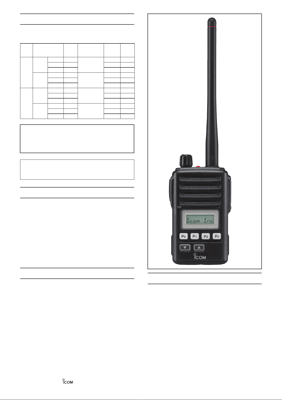
• Dimensions (Projections not included) : 56.0 (W)×97.0 (H)×36.4 (D) mm; 2 7/32 (W)×3 13⁄16 (H)×1 7⁄16 (D) in.
• Weight (Incl. BP-227) : Approx. 280 g; 9 7/8 oz.
MTRANSMITTER
• Output power : 5 W (High)/2 W (Low2)/1 W (Low1)
• Modulation : Variable reactance frequency modulation
• Maximum frequency deviation : ±5.0 kHz (Wide)
±4.0 kHz (Middle) [EUR] only
±2.5 kHz (Narrow)
• Frequency stability : ±2.5 ppm
• Spurious emissions : 70 dB typ. [USA], [EXP], [CHN]
0.25 μW (≤1 GHz), 1.0 μW (>1 GHz) [EUR]
• Adjacent channel power : 70 dB min. (Wide, Middle)
60 dB min. (Narrow)
• Audio harmonic distortion : 3% (at AF 1 kHz 40% deviation)
• FM Hum and noise (without CCITT filter)
[USA], [EXP], [CHN] only
: 40 dB min., 46 dB typ. (Wide)
34 dB min., 40 dB typ. (Narrow)
• Residual modulation (with CCITT filter)
[EUR] only
: 50 dB min., 55 dB typ. (Wide)
43 dB min., 53 dB typ. (Middle)
40 dB min., 50 dB typ. (Narrow)
• Limitting charact of modulator : 60–100% of max. deviation
• Microphone impedance : 2.2 kΩ
MRECEIVER
• Receive system : Double-conversion superheterodyne system
• Intermediate frequencies : 1st IF: 46.35 MHz, 2nd IF: 450 kHz
• Sensitivity : 0.25 μV typ. at 12 dB SINAD [USA], [EXP], [CHN]
–4 dBµ V (EMF) typ. at 20 dB SINAD [EUR]
• Squelch sensitivity (at threshold) : 0.25 μV typ. [USA], [EXP], [CHN]
–4 dBµ V (EMF) typ. [EUR]
• Adjacent channel selectivity : 70 dB min., 75 dB typ. (Wide, Middle)
60 dB min., 65 dB typ. (Narrow)
• Spurious response : 70 dB
• Intermodulation rejection ratio : 70 dB min., 74 dB typ. [USA], [EXP], [CHN]
65 dB min., 67 dB typ. [EUR]
• Hum and noise (without CCITT filter)
[USA], [EXP], [CHN] only
: 40 dB min., 45 dB typ. (Wide)
34 dB min., 40 dB typ. (Narrow)
• Hum and noise (with CCITT filter)
[EUR] only
: 45 dB min., 55 dB typ. (Wide)
43 dB min., 53 dB typ. (Middle)
40 dB min., 50 dB typ. (Narrow)
• Audio output power
(at 5% distortion with an 8 Ω load)
: 0.7 W typ. (max. audio with internal speaker)
0.5 W typ. (max. audio with external speaker)
• Audio output impedance : 8 Ω
Specifications are measured in accordance with TIA/EIA 603 ([USA], [EXP], [CHN]) or EN 300 086 ([EUR]).
All stated specifications are subject to change without notice or obligation.

2 - 1
SECTION 2 INSIDE VIEWS
CPU CLOCK
(X401: CR-764)
RESET IC
(IC408: BD5242G)
CPU
(IC401: HD64F2268TFV)
AF POWER AMP
(IC405: TDA8547TS)
EXPANDER
(IC410: CD4094BPWR)
EXPANDER
(IC12: CD4094BPWR)
MIC AMP
(IC407: NJM12904V)
AF BUFFER, AF MIXER
(IC5: NJM12904V)
AF BUFFER
(IC6: NJM12904V)
TX POWER AMP
(Q7: RD07MVS2-T112)
DRIVE AMP
(Q8: RD01MUS1-T113)
LOCK VOLTAGE SWITCH
(IC17: TC4S66F)
BASE BAND IC
(IC10: AK2346)
RF CIRCUITS
• FRONT UNIT
• MAIN UNIT
EEPROM
(IC409: HN58X24256FPIE)
DISCRIMINATOR
(X1: CDBKB450KCAY24)
DAC
(IC6: M62363FP-650C)
VIBRATION MOTOR
(MF1: QX10A(R5.5X3))

3 - 1
SECTION 3 DISASSEMBLY INSTRUCTION
1. REMOVING THE CHASSIS UNIT
qUnscrew the ANT nut, and remove the VR knob.
wRemove the VR washer, and unscrew the top screw.
eUnscrew side screws and washers.
rUnscrew bottom screws.
tTake off the CHASSIS UNIT in the direction of the
arrow.
yDisconnect the flat cable from the CHASSIS UNIT
(MAIN UNIT).
2. REMOVING THE FRONT UNIT
qDisconnect the VR cable from J402.
wDisconnect the flat cable from J403.
3. REMOVING THE MAIN UNIT
qUnsolder 6 points from the shield cover.
wUnsolder 4 points from the contact spring.
eUnsolder 1 point from the antenna connector.
Unsolder ×6
(shield cover)
Unsolder ×4
(contact spring) Unsolder ×1
(antenna connector)
MAIN UNIT
CHASSIS
VR knob
ANT nut
Flat cable
VR washer
Top screw
Side screw & Washer
Bottom screws
Side screw & washer
rUnscrew 2 screws, and remove the shield cover.
t
Disconnect the motor connector* from the MAIN UNIT.
Shield cover
Unscrew ×2
Disconnect
(motor connector)
CHASSIS
MAIN UNIT
Unscrew ×5
CHASSIS
MAIN UNIT
yUnscrew 5 screws, and take off the MAIN UNIT.
VR cable
Flat cable
J403
J402
eUnscrew 4 screws.
rUnsolder 2 points (at the speaker leads).
tTake off the FRONT UNIT in the direction of the
arrow.
FRONT UNIT
Unscrew ×4
Unsolder ×2
(Speaker leads)
*
*: Except [A], [D], [G], [J]

4 - 1
SECTION 4 CIRCUIT DESCRIPTION
While transmitting, serial-connected PIN diodes are ON,
thus the TX line is connected to the antenna, and the RX
line is connected to the GND simultaneously to prevent TX
signal entering.
The limitter protects RX line from over-level RF inputs, and
the BEF (=trap) damps unwanted signals to GND.
The tuned-BPF is adjusted so that it responds to receiving
frequency and rejects all others, by the variable capacitor
whose capacitance is varied by added voltage "T1" and "T2."
The RF AMP amplifies RX signals to a level suited to the 1st
mixer.
4-1 RECEIVER CIRCUITS
RF CIRCUITS
RF circuits consist of RF filters, antenna switch (ANT SW),
RF amplifier (RF AMP), etc., and extracts and amplifies the
signals of frequency which desired to receive.
The received signals (RX signals) from the antenna are passed
through the LPF, ANT SW (as an LPF in RX), limitter , BEF
(Band Eliminate Filter) and the two-staged tuned BPF. The
filtered RX signals are amplified by the RF AMP, and passed
through another two-staged tuned BPF. The filtered RX signals
are then applied to the 1st IF circuits.
The ANT SW toggles RX line and TX line. While receiving,
the TX line and the antenna is disconnected to prevent RX
signals entering. The RX line is disconnected from the GND
simultaneously, and an LPF which guides received signals
to the RX circuits is composed.
1ST IF CIRCUITS
The 1st IF circuits consist of 1st mixer, 1st IF filter and 1st IF
amplifier (IF AMP). And it converts the RX signals into the
1st IF signal, then filters to remove unwanted signals and
amplifies.
The filtered RX signals are applied to the 1st mixer to be
converted into the 1st IF signal, by being mixed with the 1st
Local Oscillator (LO) signals “1stLO” from the RX VCO via
the LPF.
C55
D10
L13
C60
FL-335
FI1
1
IN
2OU T 3
GND
4GND
56
R30
R48
1stIF
R25
Q3
L14
2
C54
Q4
C322
D9
R2 2
R34
C56
C5 8 C4 1
C5 1
1
R31
R20
C39
C53
C324
C36
C44
C52
R3 3
3
R23
L11
R29
R21
C48
C35
L1
1stLO
2
C183
C321
C323
R26
R35
R32
C57
C50 R28
C59
C329
R2 7
C45
C38
C40
D26
C49
R5V R5V R5V
LPF
LIMITTER
1st IF
AMP
1st
MIXER
Two-staged
TUNED BPF
1st IF
FILETR
C14
D10
C26
C186
R11
L14
R12
R172
C42
6P
C25
R15 R18
R13
C322
D9
R2 2
C28
C27
C4 1
L5
C2 2
R20
C39
D23
C324
C36
C44
L6
D6
L31
C19
C23
C43
C17
Q2
R23
C37
L11
D8
R21
R171
Q1
L7
C20
R19
R174
L9
C29
C35
L1
1stLO
2
C183
R173
C24
C184
C32
R213
C323
C16
R14
C18
C33
R175
D5
L8
R16
C31
R17
D4
C30
C45
C38
D7
C40
C49
T2
T1
RSSI
R5V
BEF
LPF
LPF (ANT SW)
LPF
LIMITTER
RF
AMP
AGC LINE
DRIVER
Two-staged
TUNED BPF
Two-staged
TUNED BPF
C2
To ANT
L2 L1C6
C5
C1
R51
C4
C3
To TX AMP
The converted 1st IF signal is passed through the 1st IF filter
to be removed unwanted signals. The filtered 1st IF signal is
applied to the 1st IF AMP via the limitter. The amplified 1st
IF signal is then applied to the 2nd IF circuits.
• RF CIRCUITS
• 1ST IF CIRCUITS

4 - 2
2ND IF AND FM DEMODULATOR CIRCUITS
The 2nd IF circuits consist of 2nd mixer, 2nd IF filter, 2nd
IF amplifier. And it converts the 1st IF signal into the 2nd
IF signal, then filters to remove unwanted signals and
amplifies. IF IC "TA31136FNG" contains whole of the 2nd IF
circuits and FM demodulator circuit too.
The 1st IF signal is applied to the IF IC, and converted into
the 2nd IF signal, by being mixed with the 2nd LO signal
(from the X2 via the PLL IC (IC4, pins 1, 2) and tripler), at
internal 2nd mixer. The converted 2nd IF signal is filtered by
external 2nd IF filter (ceramic filter), and saturation-amplified
by internal 2nd IF AMP. The amplified 2nd IF signal is
FM-demodulated by the quadrature detector.
The demodulated AF signals "SQLI" are applied to the RX
AF circuits.
C169
C67
1stIF
C69
R38
C65
R42
L35
C166
C185
C161
C66
C6 1
Q19
C162
R4 5
C168 C6 2
C165
C167
R46
C188
L33
R4 3
C70
TA31136FNG
IC1
1OSCIN
2OSCOUT
3M IXOUT
4VCC
5IFIN
6DEC
7FILOUT
8FILIN 9
AFOUT
10
QUAD
11
IFOUT
12
RSSI
13
N-DET
14
N-REC
15
GND
16
MIXIN
C68
X1
C71
C163
C63
FI2
IO
R3 9
R4 4
C75
C164
R115
Ref.Freq.
R116
R40
R36
NOIS
RSSI
SQLI
SQLO
IF IC
QUADRATURE
DETECTOR
2nd IF
FILTER
TRIPLER
(×3)
NOISE
FILTER
2nd
Mixer
FM
Detector
16
Noise Det.
Noise
AMP
RSSI
1110
Noise
Filter
2nd IF
AMP
IF IC (TA31136FNG) BLOCK DIAGRAM
914
12
2
873
5
RX AF CIRCUITS
The RX AF circuits consist of AF filters, AF amplifier (AF
AMP), AF power amplifier, etc., and amplify, filter the AF
signals FM-demodulated by the FM IF IC.
This transceiver employs the base band IC for audio signal
processing for both transmit and receive. The base band
IC is an audio processor and composed of RF AMPlifier,
compressor, expander, scrambler, etc. in its package.
The demodulated AF signals from the IF IC are applied to
the base band IC (IC10, pin 23). The applied AF signals are
amplified at the amplifier section and level adjusted at the
volume controller section, then suppressed unwanted 3 kHz
and higher audio signals at LPF. The filtered AF signals are
applied (bypassed) the TX/RX HPF, scrambler, de-emphasis
sections in sequence.
The TX/RX HPF filters out 250 Hz and lower audio signals,
and the de-emphasis circuit obtains –6 dB/oct of audio
characteristics. The expander expands the compressed
audio signals and also noise reduction function is provided.
The AF signals are then level adjusted at the volume
controller section and amplified at the amplifier section, then
output from pin 20 (IC10).
The processed AF signals from the base band IC (IC10) are
applied to the FRONT UNIT via J1 (MAIN) and J401
(FRONT).
The AF signals from the MAIN UNIT "SIGNAL" are passed
through the AF mute SW, LPF and variable register (VR
UNIT) for audio level adjustment, then applied to the AF
power AMP. The amplified AF signals "AFO" are applied to
the internal speaker, or external speaker via the [SP MIC]
jack (MP701; CHASSIS).
Scrambler/
De-scrambler
TX/RX
HPF
Pre-
emphasis Limiter Splatter VR2
Expander VR4
RXA2
SMF
De-
emphasis
Com-
pressor
VR1
(HPF)
RX
LPF
VR3
(HPF)
7 MOD
18
19
20 SIGNAL
3TXIN
• BASE BAND IC BLOCK DIAGRAM
23RXIN
21SDEC
TXA1
RXA1
BASE BAND IC (IC10)
• 2ND IF AND FM DEMODULATOR CIRCUITS

4 - 3
4-2 TRANSMITTER CIRCUITS
TX AF CIRCUITS
The TX AF circuits consist of microphone amplifier (MIC
AMP) and AF filters. The AF filter cuts off the signals except
voice signals (300 Hz or lower and 3 kHz or higher).
The audio signals from the internal microphone (MIC
signals) are passed through MIC mute SW and amplified by
two MIC AMPs (#1 and #2).
The MIC signals from the external microphone "EXMIC” are
applied to the FRONT UNIT via [SP MIC] jack, and amplified
by MIC AMP (#2).
The amplified MIC signals "MIC” are applied to the MAIN
UNIT via J401(FRONT UNIT) and J1 (MAIN UNIT).
The MIC signals from the FRONT UNIT are applied to the
baseband IC (IC10, pin 3) and processed.
SQUELCH CIRCUITS
• NOISE SQUELCH
The noise squelch cuts off the AF output signals when
no RF signals are received. Extracting noise components
(approx. 30 kHz signals) in the demodulated AF signals,
the squelch circuit turns the AF power amplifier and AF
switches ON and OFF.
A portion of FM-demodulated AF signal from the IF IC is
adjusted its level (=squelch threshold level) by DAC (D/A
converter; IC6, pins 1, 2), then passed through the noise
filter (M: IC1, pins 7, 8 and R42, 44–46, C68–70) to extract
the noise components (approx. 30 kHz signals) only. The
noise components are rectified to be converted into the
pulse-type signal by noise detector to produce DC voltage
corresponding to the noise level "NOIS". Then the DC
voltage is applied to the CPU (IC401, pin 41) and compared
with the reference level preset in the CPU.
If the CPU interpretes that the noise level is higher than
preset one, the CPU sets the "AFON" signal to "High" to
turn the AF power AMP controller OFF, and the AF mute
SW is turned OFF simultaneously. Thus closing the squelch
is accomplished.
• TONE SQUELCH
The tone squelch connects the RX AF line and activates
the AF power amplifier to emit the AF signals only when
receiving a signal which contains the tone frequency
matched with preset in the CPU. Detecting signal in the
demodulated AF signals, the tone squelch circuit turns the
AF power amplifier and AF switches ON and OFF.
<CTCSS/DTCS>
A portion of FM-demodulated AF signals from the FM IF
IC are passed through the tone filter (M: Q6, pins 5, 6) to
remove unwanted voice siganls. The filtered tone signals
are applied to the CPU (IC401, pin 44).
<2/5 TONE, DTMF>
A portion of FM-demodulated AF signals are output from
the baseband IC (M: IC10, pin 21), and passed through
the tone filter (M: R136, C220) to remove unwanted voice
siganls. The filtered tone signals are applied to the CPU
(IC401, pin 43).
The CPU compars the tone frequency/code preset in the
CPU, and if the applied tone frequency/code is matched to
preset one, the CPU controls the AF power AMP and AF
mute SW as same as "NOISE SQUELCH."
C512
R524
C405
R522
C437
C497
Q406
Q401, Q402
C510
R525
C513
R446
C404
W401
C421
R518
R407
R408
SP401
Q415
R511
R426
R519
R405
R513
W402
C496
C502
C481
C407
R401
R428
IC403
13
12
14
R539
C426
R520
C498
IC406
1
2
3
45
6
7
8
MC401
C503
C482
C435
R537
R433
R541
J402
1
2
3
4
56
C425
R523
C401
Q413
IC407
2
3
1
C406
R402
R445
R521
R538
R517
C423
R406
R430
R434
IC407
6
5
7
R432
R535
R512
R429
IC405
1
GND1 2
NC 3
OUT1 + 4
MODE 5
SVRR 6
SELECT 7
NC 8
OUT2 + 9
NC 10
GND2
11 VCC2
12 NC
13 OUT2-
14 IN2-
15 IN2+
16 IN1+
17 IN1-
18 OUT1-
19 NC
20 VCC1
SIGNAL
AFON
VCC
BEEP
DUSE
MIC
EXMIC
SPON
AFON
BPMAX
PWON
AFO
VR UNIT
W601
1
2
3
4
MIC/AF
MUTE SW
MIC AMP
#1 MIC AMP
#2
LPF
AF POWER AMP
CONTROLLER
AF POWER AMP
AUDIO
LEVEL
ADJUST
DAC
1 2 Noise
AMP
Fc=30 kHz
Active filter
From IF IC (Pin16)
To RX AF circuits
Noise detector
Rectify
“NOIS”
NOISE SQUELCH DIAGRAM
• TX AF CIRCUITS

4 - 4
<CTCSS/DTCS>
CTCSS/DTCS signals ("CEN0"–"CEN2") are generated by
the CPU (F: IC401, pins 79–81) and converted its wave
form by R461–R463 (F), then passed through the LPF (F:
IC403, pins 3, 1). The filtered CTCSS/DTCS signals are
then level-adjusted by DAC (M: IC6, pins 9, 10) and applied
to the AF mixer (M: IC5, pin 2) to be mixed with MIC signals,
then applied to the TX VCO as the modulation signals. The
CTCSS/DTCS signals are also applied to the reference
signal oscillator (M; X2) too, via the buffer (M: IC16, pins 2, 1).
<2/5 TONE, DTMF>
2/5 tone and DTMF signals are ("SEN0"–"SEN3") are
generated by the CPU (F: IC401, pins 72–75) and converted
its wave form by R471–R474 (F), then passed through
the two-staged LPF (F: IC403, pins 5, 7 and pins 10, 8).
The filtered 2/5 tone and DTMF signals are applied to the
AF mixer (M: IC5, pin 2) to be mixed with MIC signals.
The mixed signals are then applied to the TX VCO as the
modulation signals). The CTCSS/DTCS signals are also
applied to the reference signal oscillator (M: X2, pin 1) too,
via the buffer (M: IC16, pins 2, 1).
The modulated VCO output is buffer-amplified by two buffers
(Q12, Q10), and applied to the pre-driver via TX/RX SW.
C126
R65
C107
R87
C99
0.001
C93
TX
C129
C190
C122
L21
C195
C110
L41
C103
L42
L27
Q12
R82
from VCO
C191
C127
R72
C113
D1 6
C194
D21
L38
C193
C118
C148
C95
1stLO
To PLL
R8 4
C102
R71
C124
C108
0.01
C104
R69
C114
R81
R9 8
L43
R88
L26
R67
D17
EP1
R76
Q15
1
2
34
5
Q11
C137
C205
L25
R7 5
C105
C117
D15
C111
C120
R86
C121
Q14
D1 9
Q10
C100
LV
C109
R68
L39
R77
L24
Q17
D18
Q16
D14
D2 0
C133
C203
L37
R80
R8 5
C116
L28
R7 9
C139
C192
C119
D22
C123
R8 3
C134
C115
R78
Q13
R70
LVA
RX VCO
TX VCO
R5V
VCC
T5V
MOD
BUFFERBUFFER
BUFFER
RIPPLE
FILTER
VCO
SW
TX/RX
SW
Freq.
adjust
Freq.
adjust
Modulation
L14
C324 C183
C323
C49
LPF
• MODULATION CIRCUIT AND TX/RX VCOs
The applied MIC signals are amplified at the amplifier
(TXA1), and level adjusted at the volume controller (VR1).
The level adjusted MIC signals are applied (bypassed) the
compressor section, pre-emphasis section, TX/RX HPF,
de-scrambler, limiter, splatter, in sequence, then applied to
another volume controller.
The compressor compresses the MIC signals to provide
high S/N ratio for receive side, and the pre-emphasis obtains
+6 dB/oct audio characteristics. The TX/RX HPF filters out
250 Hz and lower audio signals, the limiter limits its level and
the splatter filters out 3 kHz and higher audio signals. The
filtered MIC signals are level adjusted at another volume
controller (VR2), and then output from pin 7 via smoothing
filter (SMF).
The output MIC signals are passed through the FM/PM
SW (IC11, pins 6, 1) and LPF (IC5, pins 2, 1) then applied
to the DAC (D/A Converter; IC6, pin 4) and level-adjusted
(deviation adjustment). The level-adjusted MIC siganls are
output from pin 3, then applied to the modulation circuit as
the modulation signals "MOD” via buffer (IC5, pins 6, 7).
MODULATION CIRCUIT
The modulation circuit FM-modulates the VCO oscillating
signal with the modulation signals from the TX AF circuits.
• VOICE SIGNAL
The buffer-amplified AF signals are applied to the variable
capacitor (VD) to change its reactance for FM modulation.
• TONE SIGNALS
Tone signals are generated in the CPU and applied to the
both of the VCO and reference frequency oscillator to be
modulated.

4 - 5
TRANSMIT AMPLIFIERS
The transmit amplifiers consist several RF amplifiers (pre-
driver, driver, power), and amplify the TX VCO output to the
transmit output level.
The TX VCO output is applied to the pre-drive amplifier via
the TX/RX switch. The amplified TX signal is amplified by
drive amplifier, then power-amplified by the power amplifier
to obtain 5 W (max.) of TX output power.
The power-amplified TX signal is passed through the LPFs
(as a harmonic filter), ANT SW (TX), and another LPF, then
applied to the antenna.
APC CIRCUIT
The APC (Automatic Power Control) circuit stabilizes
transmit output power to prevent transmit output power level
change which is caused by load mismatching or heat effect,
etc. The APC circuit also selects transmit output power from
high, middle and low power.
A portion of the TX signal is rectified by the power detector
to be converted into DC voltage which is in proportion to the
transmit output power level. The detected voltage is applied
to the comparator. The transmit power setting voltage is ap-
plied to another input terminal as the reference voltage.
The comparator compares the detected voltage and refer-
ence voltage, and the difference of voltage is output. The
output voltage controls the bias of the TX amplifiers to re-
duce/increase the gain of these amplifiers for stable transmit
output power.
The change of transmit power is carried out by changing
reference voltage.
C72
R65
C83
R59
Q7
C99
0.001
L20
C93
TX
MP 1
2681
C302
C78
C2
C81
C91
To ANT
C98
L18
C80
L16
Q9
C292
C15
C73
L2
C101
L1
C308
R61
Q8
C89
C10
R6
C6
C9
C77
R1
D1
C95
C88
R58
C79
C108
0.01
R69
C5
R55
C12
R67
R63
IC2
1
2
3
4
5
C1
R8
C7
R5
R52
R62
L19
L17
C106
D15
R57
C11
R10
C74
L15
C87
C291
R53
0
0
R54
R4
R68
C84
R51
C90
C94
C76
0.1
D14
C8
C96
R2
C4
D2
L4
D25
C85
EP2
R7
C13
C82
C97
C92
C3
R9
C86 L3
R3
T2
TMUT
LPF
LPF
R
APC CIRCUIT
COMPARATOR
TX/RX
SW
LPF
PWR
AMP
DRIVE
AMP
Pre-
DRIVE
ANT SW
(TX)
TX POWER
DETECTOR
L14
C324 C183
C323
C49
LPF
• TRANSMIT AMPLIFIERS AND APC CIRCUIT

4 - 6
4-3 FREQUENCY SYNTHESIZER CIRCUITS
VCOs
A VCO is an oscillator which its oscillation frequency is
determined by the applied voltage. This transceiver has
two VCOs; RX VCO and TX VCO. The RX VCO generates
the 1st LO signals for the 1st IF produce, and TX VCO
generates TX signal. The VCO SW toggles these VCOs.
• RX VCO
The RX VCO oscillates 89.65 to 127.65 MHz LO signals.
The generated 1st LO signals are applied to the 1st mixer
(Q3) via two buffers (Q12 and Q10) and LPF.
• TX VCO
The TX VCO oscillates 136 to 174 MHz TX signal. The
generated TX signal is applied to the pre-driver (one of TX
AMPs) via the TX/RX SW.
A portion of the VCO output is applied to the PLL IC via the
buffer (Q11).
C126
R65
C107
R87
R59
C99
0.001
C93
TX
C129
C190
C122
L21
C195
C110
L41
C103
Q9
L42
L27
Q12
R82
from VCO
C191
C127
R72
C113
D1 6
C194
R61
D21
L38
C193
C118
C148
C95
1stLO
To PLL
R8 4
C102
R71
C124
C108
0.01
C104
R69
C114
R81
R9 8
L43
R88
L26
R67
R63
D17
EP1
R76
Q15
1
2
34
5
Q11
C137
C205
R62
L19
L25
C106
R7 5
C105
C117
D15
C111
C120
R86
C121
Q14
D1 9
Q10
C100
LV
C109
R68
L39
R77
L24
C90
Q17
C94
D18
Q16
D14
D2 0
C133
C203
L37
R80
C96
R8 5
C116
L28
R7 9
C139
C192
C119
D22
C123
R8 3
C134
C92
C115
R78
Q13
R70
LVA
RX VCO
TX VCO
R5V
T5V
MOD
BUFFERBUFFER
BUFFER
RIPPLE
FILTER
VCO
SW
TX/RX
SW
Pre-
DRIVE
Freq.
adjust
Freq.
adjust
Modulation
L14
C324 C183
C323
C49
LPF
• PLL CIRCUITS
R92
C126
D24
CP1
R105
R94
R87
C129
C155
C158
C190
C122
C1
3
C195
R9 3
C213
L32
L42
L27
R82
from VCO
C191
Q18
C127
C113
D1 6
C194
R10
1
D21
47K
L38
C193
R103
C118
C141
C148
C209
R8 4
C124
C104
C153
C114
R100
R81
L43
R
L26
C152
R118
3.3 MSVA
C147
D17
R96
C143
0.001
A CZ1005Y
EP6
C1
5
C137
CR-783
X2
1VCON
2GND 3
OUT
4
VCC
C211
L25
R109
C117
C120
R86
C157
C121
R9 5
Q14
D1 9
C149
R97 LV
E
L39
L24
R90
C146
R110
C151
C140
D18
C156
D2 0
C133
C203
L37
R8 5
C116
L28
R7 9
C150
R187
C138
C154
C192
C119
D22
R108
R104
C123
R8 3
IC16
2
3
1
R117
C132
C134
C115
R9 1
R89
C208
C207
C145
C206
MB15A02PFV1
IC4
1
OSCIN 2
OSCOUT 3
VP 4
VCC 5
DO 6
GND 7
LD 8
FIN
9CLOCK
10 DATA
11 LE
12 FC
13 NC
14 FOUT
15 P
16 B
Q13
BAL
REF
PLST
SCK
SO
LVA
UNLK
LVIN
RX VCO
TX VCO
PLL
S5V
MOD
LOOP
FILTER
LPF
PLL IC
Ref. Freq.
OSCILLATOR Freq.
adjust
Freq.
adjust
Modulation
PLL (Phase Locked Loop) CIRCUIT
The PLL circuit provides stable oscillation for both of the
transmit and 1st LO frequencies (for receive). By comparing
the feed backed VCO output and the reference frequency
signal, the oscillating frequency is stabilized.
The PLL output frequency is controlled by the serial data
including divide ratio from the CPU.
A portion of VCO output from the buffer (Q11) is applied
to the PLL IC via LPF. The applied VCO output is divided
according to the serial data including divide ratio from
the CPU, at the prescaler and programmable divider. In
the same way, the reference frequency signal from the
reference frequency signal oscillator is applied to the PLL
IC and divide so that these are the same frequency.
The frequency-matched signals are applied to the phase
comparator and phase-compared. The resulted phase
difference is detected as a phase-type signal, and level-
adjusted at the charge pump then output. The output pulse
type signal is passed through the loop filter to be converted
into the DC voltage (=Lock Voltage).
Applying the lock voltage to the variable capacitors
(VD) which composes a part of the resonator of VCO,
the capasitance of VDs changes corresponding to the
applied lock voltage. This causes the change of resonation
frequency that determines the VCO oscillating frequency to
keep the VCO frequency constant.
When the oscillation frequency drifts, its phase changes
from that of the reference frequency, causing a lock voltage
change to compensate for the drift in the VCO oscillating
frequency.
• VCOs AND BUFFERS

4 - 7
VIBERATION MOTOR CIRCUIT
(except [A], [D], [G], [J])
MF1 is a vibration motor. When the matched RX code signal
is received, MF1 rotates to produce viberation.
In vibration mode, and when the transceiver is called, "VIB"
signal from the expander (IC12, pin 6) turns to "High(=VCC
level)" and motor driver (Q30, Q31) is activated to rotate the
vibration motor (MF1).
AGC (Automatic Gain Controller) CIRCUIT
The AGC circuit effectively reduces the RX signal level if
the signal is strong, and raises it when it is weaker. The
AGC circuit detects the overall strength of the signal and
automatically adjusting the gain of the RF AMP to maintain
an approximately constant average level of the received
signals.
RSSI signal which is in proportion to the RX signal level is
applied to the gate terminal of AGC line driver. The driver
controls the voltage which supplied to the RF AMP to
control the gain of RF AMP.
C26
C186
R11
R12
R172
C
42
6P
C25
R15 R18
R13
D9
R2 2
C28
C2 2
R20
C39
D23
C36
C23
Q2
C37
D8
R171
Q1
L7
C20
R19
R174
L9
C29
C35
R173
2
4
C184
C32
R213
R14
C33
R175
L8
R16
C31
R17
D4
C30
C38
R5V
RF
AMP
AGC LINE
DRIVER
Two-staged
TUNED BPF
• AGC CIRCUIT
+5
REG
IC9
T5
REG
REG
R5
Q22
Q21
REG
S5
Q23 Q24 Q25
VCC
+5V
S5V
R5V
T5V Pre-drive AMP (Q9), APC AMP (IC2), etc.
IF IC (IC1), 1st IF AMP (Q4), 1st mixer (Q3), RF AMP (Q2), etc.
PLL IC (IC4), VCOs, etc.
Base-band IC (IC10), DAC (IC6), etc.
CPU (IC401), EEPROM (IC409), expander (IC410)
S5C
R5C
T5C
CPU5
PWR
MAIN UNITVR UNIT
FRONT UNIT
FRONT UNIT
R601
SW
POWER
Q26
F1 1
BATTERY PACK
2
4-5 VOLTAGE BLOCK DIAGRAM
Voltage from the battery pack is routed to whole of the transceiver via switches and regulators.
Q31
MF1
R202
C317
C315
Q30
C316
R203
C318
R201 VIB
VCC
M
• MOTOR DRIVER
4-4 OTHER CIRCUITS

4 - 8
Pin
No.
Line
name Description I/O
1–
11 SEG23–13
LCD segment ports. O13 SEG12
15–
25 SEG11–1
26 SO Serial data to DAC (M: IC6) and
audio strage IC (M: IC18). O
27 SCK Serial clock to DAC (M: IC6) and
audio strage IC (M: IC18). O
28 MDIO Data I/O for baseband IC (M: IC10). I/O
29 MSCK Clock to the baseband IC (M: IC10). O
30 SS Chip select signal to the Voice
strage IC* (M: IC18). O
31 PLST Strobe signal to the PLL IC (M: IC4). O
32 SDA Serial data to DAC and voice strage
IC* (M: IC18). O
33 SCL Serial clock to DAC (M: IC6) and
voice strage IC* (M: IC18). O
34 INT Interupt signal to voice strage IC* (M:
IC18). O
35 EXSF Strobe to the expander (F: IC410). O
36 EXSM Strobe to the expander (M: IC12) O
37 EXOE
Output enable signal to the
expander ICs (F: IC410 and M:
IC12).
O
38 BEEP Beep sounds. O
39 MTDT Data (MSK TX data) to the
baseband IC (M: IC10). O
40 MTCK Clock (for MSK TX data) to
baseband IC (M: IC10). O
41 NOISE Noise level from FM IF IC (M: IC1). I
43 SDEC Tone signals (DTMF, 2/5tone). I
44 CDEC CTCSS/DTCS signals. I
45 VOXV VOX detect.
"High"=start to transmit. I
46 KR1
Key input for [UP], [P0] and [P3]
keys.
(Pulled up)
I
47 KR0 Key input for [DOWN], [P1] and [P2]
keys. (Pulled up) I
48 BATV Battery volatge for monitoring. I
49 LVIN Lock voltage for monitoring. I
50 RSSI RSSI voltage from FM IF IC (M:
IC1). I
51 TEMP
Voltage divided by thermal register
(M: R190) and R191. (temperature
monitor)
I
52 OPTV Optional unit detect.
"High"=An optional unit is connected. I
55 UNLK PLL unlock signal from IC4.
"Low"=PLL is unlocked. I
59 RES Reset signal from the reset IC (F:
IC408). I
68 BPMAX
Beep sound level control signal to
BEEP SW (F: Q415).
"Low"=Maximum beep sound level.
O
69 RAC Row address clock to the Voice
strage IC* (M: IC18). O
Pin
No.
Line
name Description I/O
70 PTT [PTT] key (F: S401).
(Pulled up) I
71 MDIR Serial data I/O control signal to the
baseband IC (M: IC10). O
72–
75
SENC3–
SENC6 2/5 tone, DTMF signals. O
78 MRDF MSK data RX flag/flame detect
signal to the baseband IC (M: IC6). O
79–
81
CENC0–
CENC2 CTCSS/DTCS signals. O
82 DAST Strobe signal to the DAC (M: IC6). O
88–
91
COM4–
COM1 LCD common terminals. –
92–
100 SEG32–24 LCD segment ports. O
*; [C], [F], [I], [L] only
4-6 CPU (F: IC401) PORT ALLOCATION

5 - 1
SECTION 5 ADJUSTMENT PROCEDURE
5-1 PREPARATION
¤ REQUIRED EQUIPMENTS
EQUIPMENT GRADE AND RANGE EQUIPMENT GRADE AND RANGE
Cloning software CS-F50V CLONING SOFTWARE
(Revision 1.0 or later)
JIG cable
(Modified OPC-
966C/UC)
(See the page 5-3)
RF power meter
(terminated type)
Measuring range : 0.1–10 W
Frequency range : 100–300 MHz
Impedance : 50 Ω
SWR : Less than 1.2 : 1
Standard signal
generator (SSG)
Frequency range : 0.1–300 MHz
Output level : 0.1 mV to 32 mV
(–127 to –17 dBm)
Frequency counter
Frequency range : 0.1–300 MHz
Frequency accuracy: ±1 ppm or better
Input level : Less than 1 mW
Oscilloscope Frequency range : DC–20 MHz
Measuring range : 0.01–20 V
AC millivoltmeter Measuring range : 10 mV to 10 V
Modulation
Analyzer
Frequency range : 30–300 MHz
Measuring range : 0 to ±10 kHz External speaker Input impedance : 8 Ω
Capacity : More than 1 W
Audio generator Frequency range : 300–3000 Hz
Output level : 1–500 mV Attenuator Power attenuation : 30 dB
Capacity : More than 10 W
¤ CLONING ADJUSTMENT CHANNELS
Before starting adjustment, clone adjustment frequencies and other conditions into the transceiver using CS-F50V
CLONING SOFTWARE as below.
• ADJUSTMENT CHANNELS
CAUTION!: BACK UP the originally programmed memory data in the transceiver before programming the adjustment frequen-
cies. When program the adjustment frequencies into the transceiver, the transceiver’s memory data will be overwrit-
ten and lose original memory data at the same time.
NOTE: FOR [EUR], [EUR-01] AND [EUR-02], when adjust “Devation” and “Modulation Balance” in the middle band, change the
bandwidth to “Middle” as below.

5 - 2
¤ STARTING SOFTWARE ADJUSTMENT
qConnect the transceiver and PC with OPC-966/U. (see the page 5-3)
wTurn the transceiver power ON.
eBoot up Windows, and click the program group ‘CS-F50V’
in the ‘Programs’ folder of the [Start] menu, then
CS-F50V’s window appears. (Or click the shortcut
‘CS-F50V’
on the desktop.)
rClick [Adjust Read] button.
[Clone Write]
[I/O Update F5]
[I/O Check]
[Adjust Read]
*This screen is an example only. Each transceiver has its own specific values for each setting.
tThe 'CAUTION' dialog appears. Click [OK].
yThe adjustment window shows transceiver’s condition and adjustment items as below.
uSet or modify adjustment data as specified in the guidances (pages 5-4 to 5-12).
iWhen the adjustment is completed, click [Clone Write] button.

5 - 3
to an RS-232C port
JIG CABLE
JIG CABLE
RS-232C cable
(straight)
PC
CAUTION: Attach the [SP
MIC] jack snugly, but do
not overtighten.
An overtightened jack will
damage the connector
pins in the transceiver.
OPC-966
(RS-232C type)
OPC-966U (USB type)
Add a jumper wire here
OPC-966U
(USB type Cloning cable)
+
GND
MIC
PTT
GND
GND
SP
PTT SWITCH
+−
AC MILLIVOLTMETER
(10 mV to 10 V)
AUDIO GENERATOR
(300–3000 Hz/1–500 mV)
+−
+−
<SETTING>
Frequency
: 1 kHz
Level : 150 mV rms
4.7 µF
EXT. SPEAKER
(1 W/8 Ω)
PTT SWITCH
+
MICE
MIC
PTT
PTTE
Add a jumper wire here
OPC-966
(RS-232C type Cloning cable)
AUDIO GENERATOR
(300–3000 Hz/1–500 mV)
+−
+−
AC
MILLIVOLT-
METER
(10 mV to 10 V)
SETTING;
Freq.
: 1 kHz
Level : 150 mV rms
4.7 µF
GND
SP
+−
EXT. SPEAKER
(1 W/8 Ω)
▄PC CONNECTIONS
▄JIG CABLES

5 - 4
5-2 FREQUENCY ADJUSTMENT
Select an adjustment item using [↑] / [↓] keys, then set to the specified value using [←] / [→] keys on the connected PC’s keyboard.
ADJUSTMENT
[ADJUST ITEM] ADJUSTMENT CONDITION OPERATION VALUE
PLL LOCK
VOLTAGE
[RX LVA]
1•
•
Channel : 1-1
Receiving
Click [I/O Update (F5)] in the [Adjust]
menu (see the page 5-2), then check
the “LVIN” item on the I/O check win-
dow as below.
3.5 V
[TX LVA] 2 •
•
•
Channel : 1-1
Connect an RF Power Meter to the
antenna connector.
Transmitting
3.5 V
CONVENIENT: The “PLL LOCK VOLTAGE” can be adjusted automatically.
1: Set the Lock voltage preset ([RX LVA] and [TX LVA]) to “179.”
2: Push the [ENTER] key on the connected PC’s keyboard.
PLL LOCK
VOLTAGE
(verify)
1•
•
Channel : 1-13
Receiving
Click [I/O Update (F5)] in the [Adjust]
menu (see the page 5-2), then check
the “LVIN” item on the I/O check win-
dow as below.
0.9–1.5 V
(Verify)
2•
•
Channel : 1-13
Transmitting
0.9–1.5 V
(Verify)
RF POWER METER
(10 W/50 Ω)
Lock Voltage
Check
*This screen is an example only. Each transceiver has its own specific values for each setting.
• I/O CHECK WINDOW

5 - 5
ADJUSTMENT
[ADJUST ITEM] ADJUSTMENT CONDITION OPERATION VALUE
REFERENCE
FREQUENCY
[REF]
1 • Channel : 1-2
Connect an RF Power Meter to the
antenna connector.
Transmitting
Loosely couple a Frequency Counter to
the antenna connector.
174.000 MHz
•
•
(Loose Coupling)
FREQUENCY COUNTER
(0.1–300 MHz)
RF POWER METER
(10 W/50 Ω)
5-2 FREQUENCY ADJUSTMENT (continued)
Select an adjustment item using [↑] / [↓] keys, then set to the specified value using [←] / [→] keys on the connected PC’s keyboard.

5 - 6
ADJUSTMENT
[ADJUST ITEM] ADJUSTMENT CONDITION OPERATION VALUE
TRANSMIT
OUTPUT
POWER
(Hight)
[Hi]
1 • Channel : 1-3
Transmitting
Connect an RF power meter to the
antenna connector.
5.0 W
•
(Low2)
[L2]
2•
•Channel : 1-4
Transmitting
2.0 W
(Low1)
[L1]
3•
•Channel : 1-5
Transmitting
1.0 W
5-3 TRANSMIT ADJUSTMENT
Select an adjustment item using [↑] / [↓] keys, then set to the specified value using [←] / [→] keys on the connected PC’s keyboard.
RF POWER METER
(10 W/50 Ω)
Other manuals for IC-F50V
2
This manual suits for next models
1
Table of contents
Other Icom Transceiver manuals

Icom
Icom IC-970A User manual

Icom
Icom UHF IC-F60 User manual

Icom
Icom IC-7200 User manual

Icom
Icom IC-DELTA100H User manual

Icom
Icom IC-505 User manual

Icom
Icom IC-H16T MKII User manual

Icom
Icom IC-7300 Installation instructions

Icom
Icom IC-M602 User manual

Icom
Icom ID-52A User manual

Icom
Icom IC-V82 User manual
Popular Transceiver manuals by other brands

Kenwood
Kenwood TS-50S instruction manual

Kenwood
Kenwood TS-430S manual

SmartTrunk Systems
SmartTrunk Systems ST-2112D Service manual

Kenwood
Kenwood TH-27A instruction manual

Uniden
Uniden ATLANTIS250 BK - ATLANTIS 250 VHF Radio Guide d'utilisation

Delta Electronics
Delta Electronics Sonet OC-48/SDH Technical specifications