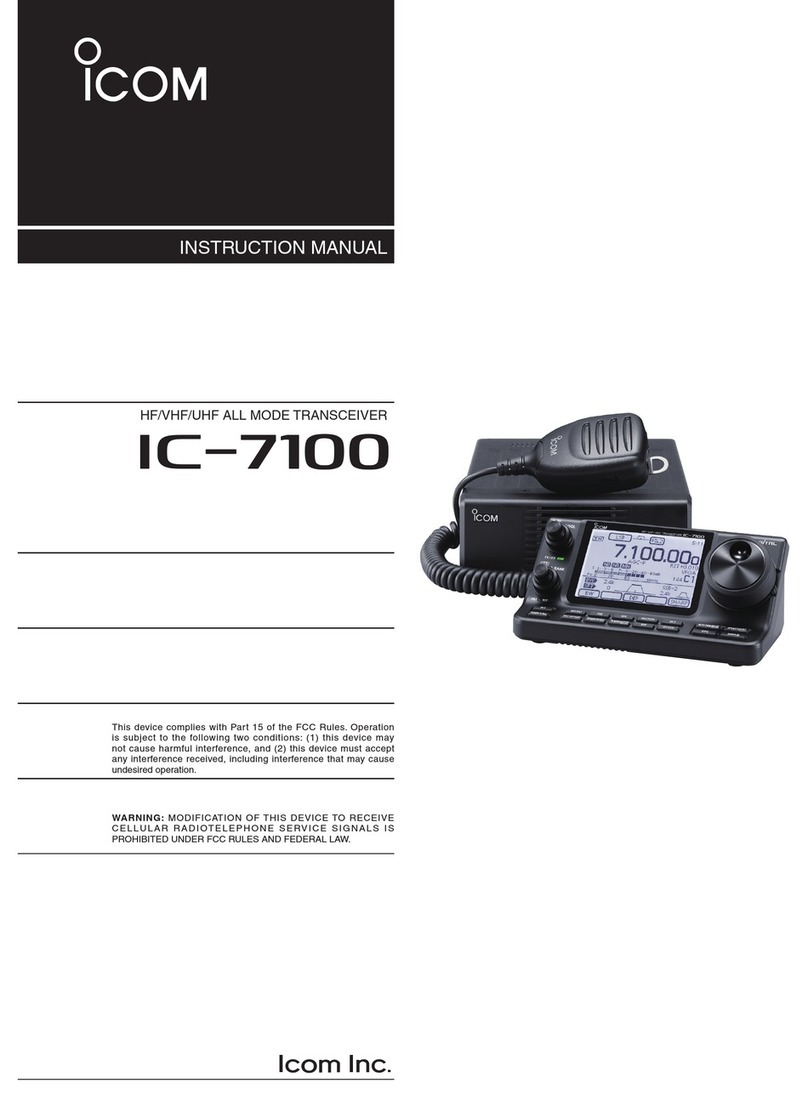
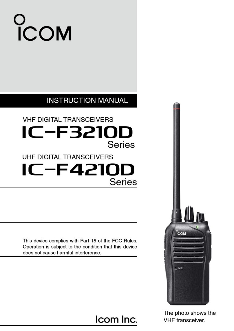
Icom iF3200DEX series User manual

OPERATING INSTRUCTIONS
iF3200DEX
series
5 SPEAKER MICROPHONE
4 NXDN™OPERATION
3 BASIC OPERATION
2 PANEL DESCRIPTION
1 ACCESSORIES
INTRODUCTION
VHF DIGITAL/ANALOG TRANSCEIVERS
iF4200DEX
series
UHF DIGITAL/ANALOG TRANSCEIVERS
(Limited functions only)

i
INTRODUCTION
FOREWORD
Thank you for choosing this Icom product.
The IDAS™NXDN™system operation is built into your
transceiver.
IMPORTANT
FIRST, CAREFULLY READ INSTRUCTIONS
qPRECAUTIONS and wINSTRUCTIONS that are
provided with the transceiver.
SAVE THIS OPERATING GUIDE— This op-
erating guide contains additional important operating
instructions for the IC-F3201DEX, IC-F3202DEX and
IC-F3203DEX v h f digital/a n a l o g t r a n s c e i v e r s and
the IC-F4201DEX, IC-F4202DEX and IC-F4203DEX
u h f digital/a n a l o g t r a n s c e i v e r s .
NOTE
To use in explosive environments, read the “SAFETY
MANUAL” leaflet that comes with the transceiver.
Icom, Icom Inc. and the Icom logo are registered trademarks
of Icom Incorporated (Japan) in Japan, the United States,
the United Kingdom, Germany, France, Spain, Russia and/
or other countries.
IDAS is trademark of Icom Incorporated (Japan).
NXDN is a trademark of Icom Incorporated and Kenwood
Corporation.
All other products or brands are registered trademarks or
trademarks of their respective holders.
1-1
Section 1ACCESSORIES
Supplied accessories..............................................................1-2
Attaching accessories ............................................................1-3
Flexible antennaD......................................................................1-3
Battery packD............................................................................1-3
Belt clipD....................................................................................1-4
Connector coverD......................................................................1-4

1ACCESSORIES
1-2
Supplied accessories
The following accessories are supplied.
Battery pack*
Belt clip* Connector cover
(with screw)
Battery charger* Power adapter*
* Not supplied, or the shape is different, depending on the transceiver’s version.
Flexible antenna
(This illustration is for the VHF type.)

1ACCESSORIES
1-3
Attaching accessories
Flexible antennaD
Connect the supplied flexible antenna to the antenna
connector.
CAUTION:
• NEVER carry the transceiver by holding only the
antenna.
• DO NOT connect any antenna other than those
listed in the basic instructions.
• Transmitting without an antenna will damage the
transceiver.
Battery packD
To attach the battery pack:
Slide the battery pack on the back of the transceiver in the
direction of the arrow (q)
until the battery release button
makes a ‘click’ sound.
To remove the battery pack:
Slide
the battery release button in the direction of the
arrow (w), as shown to the right. The battery pack is
then released, and you can remove it.
NEVER remove or attach the battery pack when the
transceiver is wet or soiled. This may result in water
or dust getting into the transceiver/battery pack and
may damage them.
NOTE: Keep the battery pack terminals clean. It’s a
good idea to occasionally clean them.
q
w
Battery release
button

1ACCESSORIES
1-4
Belt clipD
Before attaching or detaching the belt clip, remove the
battery pack if it is attached.
To attach the belt clip:
Slide the belt clip in the direction of the arrow until it➥
locks and makes a ‘click’ sound.
To detach the belt clip:
Lift the tab up (➥q), and slide the belt clip in the direc-
tion of the arrow (w).
Attaching accessories (Continued)
Connector coverD
To attach the connector cover:
Place the connector cover over the multi-connector.q
(q)
Tighten the screw. (ww)
To detach the connector cover:
Remove the screw using a Phillips screwdriver. (qe)
Detach the connector cover to connect optionalw
equipment. (r)
Belt clip
w
q
Ta b
r
e
q
w
CAUTION:
Attach the connector cover when the optional ac-
cessory is not used. Otherwise, the terminals of the
multi-connector may be shorted, and this could dam-
age the transceiver.

2PANEL DESCRIPTION
2-2
Front, top and side panels
qROTARY SELECTOR
Rotate to select the preprogrammed memory chan-
nels or scan lists, depending on the presetting.
wVOLUME CONTROL [VOL]
Rotate to turn the power ON or OFF, and adjust the
audio level.
eSTATUS INDICATOR (p. 2-3)
Lights red while transmitting.➥
Lights green while receiving a signal, or when the➥
squelch is open.
Lights/blinks orange when a matched 2/5-Tone➥
code is received, depending on the presetting.
rMULTI CONNECTOR
Connect an optional accessory.
CAUTION:
Attach the connector cover
when an optional accessory
is not used. Otherwise, the
terminals of the multi-con-
nector may be shorted, and
this could damage the trans-
ceiver.
tPTT SWITCH [PTT]
Hold down to transmit, release to receive.
yLOWER KEY [Lower]
uUPPER KEY [Upper]
A desired functions can be preset. (p. 2-4)
iEMERGENCY KEY [Emer]
A desired functions can be preset. (p. 2-4)
oANTENNA CONNECTOR
Connect the antenna.
Connector
cover
Microphone
Speaker
wVOLUME
CONTROL
eSTATUS INDICATOR
yLOWER KEY
uUPPER KEY
qROTARY
SELECTOR
oANTENNA
CONNECTOR
rMULTI
CONNECTOR
tPTT SWITCH
iEMERGENCY
KEY

2PANEL DESCRIPTION
2-3
Status indicator
• TX:
Lights Red while transmitting.
• RX busy:
On an analog channel, lights Green when the noise
squelch opens. On a digital or mixed channel, lights
Green while detecting a frame synchronization.
• Call LED:
Turns ON or blinks* when receiving a matched 2/5-
Tone, or a Call Alert.
*Depending on the presetting.
• Fast or Slow scan:
Blinks when scanning for a channel to search for a
signal.
• Low Battery 1:
You should charge the battery soon. (blinks slowly)
• Low Battery 2:
You must charge the battery. (blinks fast)
• TX low Battery 1:
Low Battery was detected in the TX mode.
• TX low Battery 2:
Very Low Battery was detected
in the
TX mode.
• Channel Error:
Continuously blinks when a non-programmed chan-
nel is selected.
• Power ON:
Blinks at transceiver startup.
R
G
O
O O
G G
G G
G G G G
The status indicator indicates the various parameters
of the transceiver as described below.
(Reference: R is Red, G is Green, O is Orange)
R O R O R O R O R O R O R O R O
R O GRO G
R R
R R R R
(When turns ON)
(When blinks)

2PANEL DESCRIPTION
2-4
Programmable function keys
The following functions can be assigned to the [Upper],
[Lower] and [Emer] programmable function keys.
LOWER KEY
UPPER KEY
EMERGENCY
KEY

2PANEL DESCRIPTION
2-5
Programmable function keys (Continued)
The following functions can be assigned to the [Upper],
[Lower] and [Emer] programmable function keys.
SCAN
Push to start and cancel scanning.
• When the scan started with the Power ON Scan or Auto
Scan function, push to pause the scan. The paused scan
resumes after the preset time period has passed.
PRIORITY A CHANNEL, PRIORITY B CHANNEL
Push to select the Priority A or Priority B channel.
PRIORITY A CHANNEL (REWRITE),
PRIORITY B CHANNEL (REWRITE)
Push to select the Priority A or Priority B channel.➥
Hold down [Prio A (Rewrite)] or [Prio B (Rewrite)]➥
for 1 second to assign the operating channel to the
Priority A or Priority B channel, respectively.
MEMORY CHANNELS 1, 2, 3, 4
Push to directly select memory channel 1, 2, 3 or 4, if
preprogrammed.
LONE WORKER (p. 3-13)
Hold down for 1 second to turn ON the Lone Worker➥
function.
• When the Lone Worker function is turned ON, and no
operation is performed for the preset time period, the
Emergency function is automatically turned ON.
Push to turn OFF the Lone Worker function.➥
MONITOR, MONITOR (AUDIBLE)
Push to turn the CTCSS (DTCS) or 2/5-Tone squelch➥
Mute ON or OFF.
• Only during LMR operation, push to open any squelch
functions, or deactivate any mute functions.
• Only during PMR operation, push to activate one or two
of the following functions on each channel.
- Hold down to unmute the channel (Audible mode).
- Push to mute the channel (Inaudible mode).
- Push to send a ‘reset code’ after the communication is
finished.
*Depending on the presetting.
NOTE: The unmute condition may automatically
return to the mute condition, after a preset time
period.
Depending on the presetting, holding down this key➥
for 1 second cancels a scan.
LOCK
Hold down to electronically lock all programmable keys
except [Moni(Audi)], [Call] (including Call A and Call B),
[Emergency], [Surveillance] and [Lone Worker].
HIGH/LOW (p. 3-12)
Select the transmit output power level temporarily or
permanently, depending on the presetting.
TALK AROUND
Hold down for 1 second to turn ON the Talk Around➥
function.
• The Talk Around function equalizes the transmit frequen-
cy to the receive frequency for transceiver-to-transceiver
communication.
Push to turn OFF the Talk Around function.➥
DTMF AUTODIAL
Push to transmit a programmed DTMF code.
RE-DIAL
Push to transmit the last-transmitted DTMF code.
NOTE: TX memories are cleared after turning OFF
the transceiver.
WIDE/NARROW
Push to switch the channel width to Wide.➥
Hold down for 1 second to switch the channel width➥
to Narrow.
CALL, CALL A, CALL B
Push to transmit a 2/5-Tone code.
• Tone call transmission may be necessary before you call
another station, depending on your signaling system.
• [Call A] and/or [Call B] keys may be selectable when your
system employs selective ‘Individual/Group’ calls.
EMERGENCY
Hold down for a preset time period to transmit an emer-
gency call.
• The emergency call transmits with beeps, and the status
indicator lights red.
• The transceiver can transmit an emergency call without the
beep sounding and the status indicator lighting.
• If you want to cancel the emergency call, hold down the key
again before transmitting the call.
• The emergency call is transmitted one time only, or repeat-
edly until receiving an acknowledgement signal, or until the
power is turned OFF.
Depending on the presetting, receiving a matching signal
cancels the transmission.

2PANEL DESCRIPTION
2-6
Programmable function keys (Continued)
SURVEILLANCE
Hold down for 1 second to turn ON the Surveillance➥
function.
• When this function is turned ON, the beep is not heard
and the status indicator does not light when a signal is
received, or a key is pushed.
Push to turn OFF the Surveillance function.➥
SIREN
Hold down for 1 second to sound a siren.
This function can be used for situations other than an
emergency alert, such as a security alarm for exam-
ple.
The transceiver sounds the siren until the power is
turned OFF.
ENCRYPTION
While in the digital mode, hold down for 1 second to➥
turn ON the Encryption function.
Push to turn OFF the Encryption function.➥
ANNOUNCE
Push to turn the Channel Announce function ON or
OFF.
• When this function is ON, the position of [ROTARY SELEC-
TOR] (between 1 and 16) is announced as you rotate it be-
tween 1 and 16.

3-1
Section 3BASIC OPERATION
Turning ON the power .............................................................3-2
Selecting a channel.................................................................3-3
Selecting a channelD.................................................................3-3
Priority A channel selectionD.....................................................3-3
Call procedure .........................................................................3-4
Receiving and transmitting ....................................................3-5
Transmitting notesD...................................................................3-5
DTMF transmissionD.................................................................3-6
Receiving a Stun, Kill and Revive commandD...........................3-6
Setting the Beep function .......................................................3-7
Setting the beep level..............................................................3-8
Setting the ringer level............................................................3-9
Setting the microphone gain ..................................................3-10
Setting the squelch level ........................................................3-11
Setting the output power level ...............................................3-12
Making an Emergency Call.....................................................3-13
Lone Worker Emergency CallD..................................................3-13
Man Down Emergency CallD.....................................................3-13

3BASIC OPERATION
3-2
Turning ON the power
Prior to using the battery pack for the first time, or after
not using it for a long time, you must fully charge the
pack for optimum battery life and operation. See BASIC
INSTRUCTIONS that are provided with the transceiver
for details.
Rotate [VOL] to turn ON the power.➥
[VOL]

3BASIC OPERATION
3-3
Selecting a channel
Selecting a channelD
To select the desired operating channel:
Rotate [ROTARY SELECTOR].➥
Push one of the memory channel keys, [MR-CH 1]➥
to [MR-CH 4].
Push [Prio A], [Prio B], [Prio A (Rewrite)] or [Prio B➥
(Rewrite)].
AUTOMATIC SCAN TYPE:
Selecting a channel is not necessary. When turning ON
the power, the transceiver automatically starts scan-
ning. Scanning stops when a signal is detected.
Priority A channel selectionD
When one of the following operations is performed, the
transceiver automatically selects the Priority A chan-
nel.
• Turning ON the power
The Priority A channel is selected each time the trans-
ceiver power is turned ON.
• Auto reset
The Priority A channel is selected when the Auto Reset
timer ends.

3BASIC OPERATION
3-4
Call procedure
When your system uses tone signaling (excluding CTC-
SS and DTCS), the tone call procedure may be neces-
sary prior to voice transmission.The tone signaling that
is used in the transceiver may be a selective calling
system, which allows you to call only specific station(s),
and prevents unwanted stations from contacting you.
Select a desired TX code channel or 2/5-Tone code,q
according to your System Operator’s instructions.
• This may not be necessary, depending on the preset-
ting.
Push [Call] (assigned to [Upper], [Lower] or [Emer]).w
(p. 2-5)
After transmitting a 2/5-Tone code, the remainder ofe
your communication can be made normally.
Selective calling Non-selective calling

3BASIC OPERATION
3-5
Receiving and transmitting
Receiving:
Rotate [VOL] to turn ON the power.q
Select a channel.w
Rotate [ROTARY SELECTOR].➥
Push one of the memory channel keys, [MR-CH 1]➥
to [MR-CH 4].
When receiving a call, adjust the audio output to ae
comfortable listening level.
NOTE: When the Auto TX function is ON, after re-
ceiving a matched RX code signal, the transceiver
automatically transmits its microphone audio for a
preset time period.
Transmitting:
CAUTION: Transmitting without an antenna will dam-
age the transceiver. See page 1-3 for antenna at-
tachment.
Wait for the channel to become clear to avoid interfer-
ence.
While holding down [PTT], speak into the micro-q
phone at your normal voice level.
Release [PTT] to receive.w
NOTE: To maximize the readability of your signal:
1. Pause briefly after pushing [PTT].
2.
Hold the microphone 5 to 10 cm (2 to 4 inches)
from your mouth, then speak at
your
normal voice
level.
Transmitting notesD
• Transmit inhibit function
The transceiver has several inhibit functions, which re-
strict transmission under the following conditions:
- The channel is muted. (PMR operation only)
- The channel is busy.
- A signal with an unmatched (or matched) CTCSS (or
DTCS) tone is received.
- The selected channel is a ‘receive only’ channel.
• Time-out timer
After continuously transmitting longer than the preset
time period, the time-out timer stops further transmitting.
• Penalty timer
Once the time-out timer activates, transmitting is further
inhibited for a time period determined by the penalty
timer.
• PTTID call
The transceiver automatically sends the ID code (5-
Tone, DTMF, BIIS or MDC) when [PTT] is pushed (be-
ginning of the transmission) and/or released (end of
transmission), depending on the presetting.

3BASIC OPERATION
3-6
Receiving and transmitting (Continued)
DTMF transmissionD
If the transceiver has [DTMF Autodial] assigned to it,
you can use the automatic DTMF transmission func-
tion.
Push [DTMF Autodial] to transmit the DTMF code.➥
The dispatcher can send a command signal that will
stun, kill or revive your transceiver.
When the Stun command is received, a beep sounds*,
and the transceiver becomes unusable. Receiving a
Revive command is necessary to operate the trans-
ceiver again in this case.
When the Kill command is received, a beep sounds*,
and the transceiver becomes unusable. Cloning the
transceiver is necessary to operate the transceiver
again in this case.
*Depending on the presetting.
Receiving a Stun, Kill and Revive commandD

3BASIC OPERATION
3-7
Setting the Beep function
The Beep function can be turned ON or OFF. When it is
OFF, the channel announcement is also turned OFF.
NOTE: You must turn ON the Beep function when
you set the microphone gain or the squelch level to
check the current level setting with the beep sound-
ing. (pp. 3-10, 3-11)
Rotate [VOL] to turn OFF the transceiver power.q
Set [ROTARY SELECTOR] to any channel otherw
than Channel 16.
While holding down [Lower], rotate [VOL] to turn ONe
the power to enter the Beep level adjustment mode.
Push [Lower] to turn the Beep function ON or OFF.r
• When a beep sounds after pushing [Lower], the Beep
function is ON. When no beep sounds after pushing
[Lower], the Beep function is OFF.
• If desired, push [Upper] to adjust the Beep level. See
page 3-8 for details.
Rotate [VOL] to turn OFF the power to exit the Beept
level adjustment mode.
NOTE: This operation may not be available, depend-
ing on the presetting.
[ROTARY SELECTOR]
[VOL]
[Lower]
[Upper]

3BASIC OPERATION
3-8
You can adjust the beep level between 1 and 5, or 1
(linked) and 5 (linked).
When a linked level is selected, you can adjust the beep
level by rotating [VOL].
Rotate [VOL] to turn OFF the transceiver power.q
Set [ROTARY SELECTOR] to any channel otherw
than Channel 16.
While holding down [Lower], rotate [VOL] to turne
ON the power and enter the beep level adjustment
mode.
Push [Upper] to change the beep level as shown tor
the right.
• A beep sounds every time you push [Upper]. Therefore,
you can determine the current level setting by the in-
creasing loudness of the beep that sounds.
• To determine if you have selected a linked level, set [VOL]
to minimum, then push [Upper] repeatedly, listening for
the loudest beep (level 5). Pushing [Upper] once after the
loudest beep will select 1 (Linked). Repeatedly push [Up-
per] to select the desired linked level.
Rotate [VOL] to turn OFF the power to exit the beept
level adjustment mode.
NOTE: This operation may not be available, depend-
ing on the presetting.
Setting the beep level
2
5
4
3
1
5 (Linked)
4 (Linked)
3 (Linked)
2 (Linked)
1 (Linked)
Pushing
[Upper]
[ROTARY SELECTOR]
[VOL]
[Lower]
[Upper]
This manual suits for next models
1
Table of contents
Other Icom Transceiver manuals

Icom
Icom IC-2340H User manual

Icom
Icom IC-U82 User manual

Icom
Icom IC-24AT User manual

Icom
Icom IC-F620 Guide

Icom
Icom IC-A14 User manual

Icom
Icom IC-703 User manual

Icom
Icom IC-V85 User manual

Icom
Icom IC-F29DR User manual

Icom
Icom IC-F8101 User manual

Icom
Icom DC-197 Installation and operating instructions