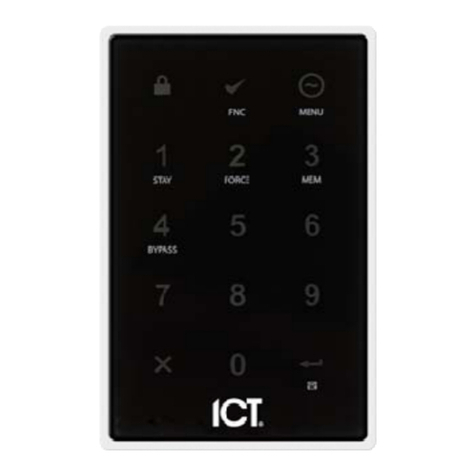
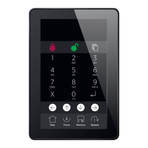
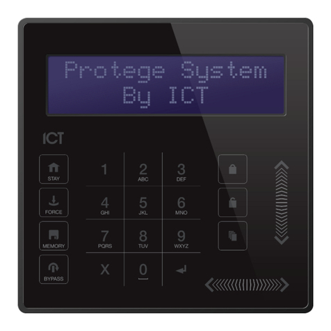
ICT PRT-TS50 User manual

PRT-TS50
Protege LCD Touchscreen Keypad
Installation Manual

The specifications and descriptions of products and services contained in this document were correct at the time
of printing. Integrated Control Technology Limited reserves the right to change specifications or withdraw
products without notice. No part of this document may be reproduced, photocopied, or transmitted in any form or
by any means (electronic or mechanical), for any purpose, without the express written permission of Integrated
Control Technology Limited. Designed and manufactured by Integrated Control Technology Limited, Protege® and
the Protege® Logo are registered trademarks of Integrated Control Technology Limited. All other brand or product
names are trademarks or registered trademarks of their respective holders.
Copyright © Integrated Control Technology Limited 2003-2021. All rights reserved.
Last Published: 08-Oct-21 2:04 PM
PRT-TS50 | LCD Touchscreen Keypad | Installation Manual 2

Contents
Introduction 4
Installation Requirements 5
Mounting 6
Mounting Instructions 6
Technical Diagram 7
Wiring Diagram 8
Communication 9
Connections 10
End of Line Termination (EOL) 10
Inputs 11
Trouble Inputs 12
Outputs 13
Configuration 14
Language 14
Keypad Address 14
Theme 14
Backlight Brightness Setting 14
Screen Timeout Setting 14
Default Configuration 14
Keypad Information 14
Keypad Functions 15
Orientation 16
Status Indicators 17
Error Messages 18
Technical Specifications 19
New Zealand and Australia 20
European Standards 21
FCC Compliance Statements 23
Industry Canada Statement 24
Disclaimer and Warranty 25
PRT-TS50 | LCD Touchscreen Keypad | Installation Manual 3

Introduction
The Protege LCD Touchscreen Keypad provides a sleek, user friendly human interface to the Protege System, an
advanced technology security product providing seamless and powerful integration of access control, security
and building automation.
The current features of the keypad include:
⦁Securely login with user codes from 1 to 8 digits.
⦁Intuitive menu function allowing scrollable options according to user security level, with quick access short cut
keys for the power user.
⦁Dual code and master code features for secure ATM and banking vault area access with automatic timeout
and delayed opening functions.
⦁Individual reportable duress code trouble for each Protege keypad.
⦁Activation of 3 reportable panic events (Panic, Medical and Fire).
⦁Smoke detector reset provided on Clear and Enter keys, selectable for an output or output group.
⦁4 inputs (duplex mode) that can be used to perform any system alarm and automation functions, along with a
dedicated enclosure tamper switch.
⦁1 low current output for driving any signaling device.
⦁5" capacitive touchscreen.
⦁480 x 800 color LCD display.
⦁Configurable for portrait or landscape orientation.
⦁Available in white or black.
PRT-TS50 | LCD Touchscreen Keypad | Installation Manual 4
Installation Requirements
This equipment is to be installed in accordance with:
⦁The product installation instructions
⦁AS/NZS 2201.1 Intruder Alarm Systems
⦁The Local Authority Having Jurisdiction (AHJ)
PRT-TS50 | LCD Touchscreen Keypad | Installation Manual 5

Mounting
The keypad should be mounted on a wall with adequate air flow around and through it.
The LCD Touchscreen Keypad can operate in either portrait or landscape orientation and can be changed by
loading the appropriate firmware version. For more information, see Orientation (page16).
Mounting Instructions
1. Select where to mount the LCD Touchscreen Keypad, ensuring it is mounted a minimum of 1.1m (3.5ft) away
from other wiring such as ACM power, computer data wiring, telephone wiring and wiring to electric lock
devices. Use the Technical Diagram provided below as a guide to correctly position the unit.
2. Hold the rear case half against the wall and mark the mounting holes and cable entry area. The cable entry
area should align with a hole cut through the plaster wall-board. Cables are intended to be run inside the wall.
Use appropriate screws (not supplied) to affix the case to the wall.
3. Run the wiring. Refer to the Communication section of this manual (see page9) for the electrical connections.
Leave about 20cm (8") of wire protruding through the center of the mounted half of the case and connect the
wiring to the reader electronics.
4. Align the top of the front body of the reader onto the recessed hinge points at the top of the rear case, then
press gently on the front body until the bottom portion snaps in to place onto the rear case.
PRT-TS50 | LCD Touchscreen Keypad | Installation Manual 6

Technical Diagram
The dimensions shown below outline the essential details needed to help ensure the correct installation of the LCD
Touchscreen Keypad.
PRT-TS50 | LCD Touchscreen Keypad | Installation Manual 7

Wiring Diagram
The end of line (EOL)
jumper should be ON
when the LCD keypad is
located at the start or end
of the module network.
Power supply
and network
communications
connection
EOL ON EOL OFF
1K
1K
Input Wiring (1K and 1K)
Common
1K
PURPLE SB
YELLOW SA
BLUE Output
BROWN Input 2
ORANGE Input 1
WHITE NB
GREEN NA
BLACK 0V
RED +12V
SHIELD
Output Wiring
Example
+12V
0V
RS-485 NA
RS-485 NB
N.C. Tamper
N.C. Tamper
Input 1 N.C.
Input Contact
1K
1K5 OHM
Reader shield is
not terminated
inside the reader
Shield wires connected
at the splice
Input N.C.
Input Contact
Shield is frame
grounded at
one point
End of Line Termination
PRT-TS50 | LCD Touchscreen Keypad | Installation Manual 8

Communication
The Protege system incorporates encrypted RS-485 communications technology for its module network. Each
system controller supports up to 250 keypads.
PRT-TS50 | LCD Touchscreen Keypad | Installation Manual 9

Connections
End of Line Termination (EOL)
The EOL (End of Line) jumper should be placed in the ON position when the keypad is inserted as the first or last
module on the RS-485 network.
EOL Jumper OFF EOL Jumper ON
PRT-TS50 | LCD Touchscreen Keypad | Installation Manual 10

Inputs
The keypad is capable of connecting to 4 inputs, each of which can be programmed to perform the required
function in the Protege system.
The following diagrams show examples of the input wiring configuration settings that can be programmed under
the input options within the Protege software.
Input (No Resistors):
Input (1K and 1K):
Input Duplex Mode (1K and 2K4):
To utilize the input duplex mode configuration shown above, the Duplex Inputs setting must be enabled in the
keypad programming (Keypads | Options 2).
PRT-TS50 | LCD Touchscreen Keypad | Installation Manual 11

Trouble Inputs
Each keypad can monitor up to 8 trouble inputs.
Trouble inputs are used to monitor the module status and in most cases are not physically connected to an
external input.
The following table details the trouble inputs that are configured in the system and the trouble type and group
that they activate.
Trouble
Input Function Type Group
KPXXX:01 Module Tamper
Opens when the keypad is removed from the wall.
Module
Tamper System
KPXXX:02 Reserved - -
KPXXX:03 Keypad Panic
Keys 1 and 3 are pressed together generating a panic message. - -
KPXXX:04
Keypad Duress
A user code with the duress option enabled has entered a code on the
keypad.
- -
KPXXX:05 Reserved - -
KPXXX:06 Reserved - -
KPXXX:07
Too Many Codes
Too many incorrect codes have been entered at the keypad and it has
been locked out for the programmed lockout time.
Number of
Attempts Access
KPXXX:08
Module Offline
The keypad has either been removed from the system or lost
communications.
Module Lost System
Replace 'xxx' with the appropriate address of the module that you are programming.
The panic and duress features have not been evaluated for UL/ULC installations.
PRT-TS50 | LCD Touchscreen Keypad | Installation Manual 12

Outputs
The keypad has 5 programmable outputs. These outputs are used to control the system status indicators, system
beeper and the open collector output. The outputs can be activated and deactivated based on specific events or
functions within the Protege System.
Output Function
KPXXX:01 Open collector output on the keypad connector (P1)
KPXXX:02 Armed status indicator (Red)
KPXXX:03 Disarmed status indicator (Green)
KPXXX:04 Beeper output
KPXXX:05 Confidentiality mode
Replace 'xxx' with the appropriate address of the module that you are programming.
Example Open Collector Output Connection (P1):
Keypad Terminal
Connection
1K5 OHM
LED
+12V AUX
Z2P1 Z1 NB +NA -
Warning: The open collector output can switch to a maximum capacity of 50mA. Exceeding this amount will
damage the output.
PRT-TS50 | LCD Touchscreen Keypad | Installation Manual 13

Configuration
Before the keypad will communicate with the Protege system it must be assigned an address.
To program an address using the system configuration menu, apply power to the keypad, and while the screen
displays Initializing press the [CLEAR] key, then the [ENTER] key. The configuration screen is displayed. Set the
available options as required.
The configuration menu can only be accessed when the keypad powers up and is initializing. It cannot be
accessed when the keypad is operational.
Language
The operating language can be selected by scrolling through the list of available language options.
Keypad Address
The address selection sets the address of the keypad. This address must be a unique address in the Protege
system that is below an address of 250.
Select the Address menu to access the setting. Use the keypad keys to set the new address and press Save to
save the setting. To exit without making changes press Cancel.
Theme
Toggle the Theme slider to select the dark or light keypad display configuration.
Backlight Brightness Setting
The backlight brightness setting adjusts the brightness of the screen when the keypad is in use.
Move the Backlight slider or use the touchscreen keypad to set the brightness level and press Save to save the
setting. To exit without making changes press Cancel.
Screen Timeout Setting
The screen timeout setting controls how long the backlight will stay on with no user interaction before dimming.
Setting the timeout to 0 will cause the backlight to never dim.
Select the Screen Timeout menu to access the setting. Use the keypad keys to set the backlight timeout (in
seconds) and press Save to save the setting. To exit without making changes press Cancel.
Default Configuration
The default option resets the keypad to the factory default settings.
Press Default to default the keypad. You will be prompted to Press [Enter] to default keypad. To exit without
defaulting the keypad press Cancel.
Keypad Information
The information screen displays configuration details about the keypad. Press Info to access the information
screen.Press Cancel to exit.
PRT-TS50 | LCD Touchscreen Keypad | Installation Manual 14

Keypad Functions
Key Function
0-9
The primary function of the numeric keys is to enter user codes. When controlling devices the
[1] key turns the device on, the [2] turns the device off, and in the on state the [3] key latches
the device.
The [ARM] key is used to start the arming process for an area.
The [DISARM] key is used to silence alarms, disarm the area, and cancel an arming sequence.
The [MENU] key is used to access the menu and can be followed by menu shortcut selection
key(s) that represent a menu item.
When the [MENU] key is held for 2 seconds, the keypad will recognize it as the [FUNCTION]
key, which can be programmed to unlock a door.
The [STAY] key is used to initiate the stay arming process for an area.
The [FORCE] key is used to force arm an area.
The [MEMORY] key will take a user directly to the memory view menu.
The [BYPASS] key can be pressed when an area is breached during an arming process to
bypass the displayed area.
The [CLEAR] key will log off the user currently logged in to the keypad. When pressed while
not logged in the display will be refreshed.
The [ENTER] key is used to confirm an action on the keypad, acknowledge memory and alarm
information, and move to the next programming screen.
ARROW
KEYS
The arrow keys are used to scroll the menu, move the focus of a program window to the next
screen, and move the cursor when programming or editing values.
PRT-TS50 | LCD Touchscreen Keypad | Installation Manual 15

Orientation
LCD Touchscreen Keypad orientation is determined by its operating firmware. The keypad can operate in either
portrait or landscape orientation and can be changed by loading the appropriate firmware version.
The required portrait or landscape version will need to be specified when downloading the keypad firmware or
requesting firmware from ICT Technical Support.
Update Keypad Firmware
Protege GX
To update firmware on the LCD Touchscreen Keypad, Protege GX controllers must be running firmware version
2.08.1140 or higher.
1. Log in to the web interface of the Protege GX controller that the keypad is associated with.
2. Navigate to the Application Software menu.
3. In the Update Module Firmware section, select the required keypad from the Module dropdown.
4. Click Upload Firmware and browse to the firmware Bin File (.bin format) supplied by ICT.
5. Open the file to install the new firmware on the selected keypad.
When the update is complete the keypad will restart in the new orientation.
Protege WX
To update firmware on the LCD Touchscreen Keypad, Protege WX controllers must be running firmware version
4.00.607 or higher.
1. Log in to the Protege WX web interface.
2. Navigate to System | Application Software.
3. In the Update Module Firmware section, select the required keypad from the Module dropdown.
4. Click Upload Firmware and browse to the firmware Bin File (.bin format) supplied by ICT.
5. Open the file to install the new firmware on the selected keypad.
When the update is complete the keypad will restart in the new orientation.
Warning: Updating module firmware will put the entire network into maintenance mode, preventing normal
activity for the duration of the update process. Module firmware must not be updated remotely.
PRT-TS50 | LCD Touchscreen Keypad | Installation Manual 16

Status Indicators
The keypad features two status indicators showing the condition of the Protege system.
Armed / Alarm Indicator
When the armed/alarm indicator is flashing the system is in alarm and you need to enter your user code to silence
the alarm. When on, the system is armed.
This indicator is programmable and may not function as described here. Verify the operation with your installation
company or security professional.
Disarmed Indicator
When the disarmed indicator is on the system is disarmed. Alternatively, when the disarmed indicator is on the
system may be ready to arm (all inputs are secure). Enter your user code to arm.
This indicator is programmable and may not function as described here. Verify the operation with your installation
company or security professional.
Confidentiality Mode
Keypads include a confidentiality mode where activation of the onboard output will cause all lights (Power,
Disarm, Arm and LCD backlight) to turn off when the keypad is not in use. This feature is enabled by default. When
the onboard output is not activated, these lights serve their normal functions.
PRT-TS50 | LCD Touchscreen Keypad | Installation Manual 17

Error Messages
When the keypad attempts to register or communicate with the system controller after powering up, errors can be
generated indicating access to the Protege system has been denied or was unsuccessful. This is a normal part of
the Protege system.
Keypad Version Error
The version of the keypad is incorrect for the system controller. This error cannot be corrected without updating
the keypad firmware. The event log in the system controller will display the version of the keypad and the version
that is required if this error has occurred.
Please contact your distributor for information on how to update the firmware.
Keypad Address Too High
The address of the keypad that is programmed is beyond the maximum number of keypads that are allowed to
connect to the controller. Press the [EXIT] key to restart the keypad. Set the keypad address to a lower value.
Duplicate Keypad Address
The address of the keypad is already programmed into the system controller. Press the [EXIT] key to restart the
keypad then set the keypad address to a free address.
Security Violation
The system controller has security enabled and devices cannot be added to the Protege system. Remove the
security setting for the system controller then press the [EXIT] key to restart the keypad.
Invalid Serial Number
The keypad has an invalid serial number programmed and cannot be registered on the Protege system. Return the
keypad to your distributor. This error cannot be corrected without updating the keypad firmware.
PRT-TS50 | LCD Touchscreen Keypad | Installation Manual 18

Technical Specifications
The following specifications are important and vital to the correct operation of this product. Failure to adhere to
the specifications will result in any warranty or guarantee that was provided becoming null and void.
Ordering Information
PRT-TS50-STD-B Protege LCD Touchscreen Keypad - Black
PRT-TS50-STD-W Protege LCD Touchscreen Keypad - White
Power Supply
Operating Voltage 11-14VDC
Operating Current 260mA (340mA Max)
User Interface
User Interface Display 480 x 800 Color LCD display
User Input 5" capacitive touchscreen
Inputs
Inputs 2 standard or 4 using Input Duplex mode
Outputs
Outputs
1 open collector (50mA Max) output. Programmable for all output functions
2 system status indicators
1 system beeper
Dimensions
Dimensions (L x W x H) 131 x 90 x 20mm (5.15 x 3.54 x 0.77”)
Weight 192g (6.77oz)
Operating Conditions
Operating Temperature -10° to 55°C (14° to 131°F)
Storage Temperature -10˚ to 85˚C (14˚ to 185˚F)
Humidity 0%-93% non-condensing, indoor use only (relative humidity)
It is important that the unit is installed in a dry cool location that is not affected by humidity. Do not locate the unit
in air conditioning or a boiler room that can exceed the temperature or humidity specifications.
Integrated Control Technology continually strives to increase the performance of its products. As a result these
specifications may change without notice. We recommend consulting our website (www.ict.co) for the latest
documentation and product information.
PRT-TS50 | LCD Touchscreen Keypad | Installation Manual 19

New Zealand and Australia
General Product Statement
The RCM compliance label indicates that the supplier of the device asserts that it complies with all applicable
standards.
PRT-TS50 | LCD Touchscreen Keypad | Installation Manual 20
Other manuals for PRT-TS50
1
Table of contents
Other ICT Keypad manuals

ICT
ICT EliteSuite ELT-KLES User manual

ICT
ICT Protege PRT-KLCD User manual

ICT
ICT PRT-KLCS User manual

ICT
ICT Protege EliteSuite User manual

ICT
ICT PRT-KLCS User manual

ICT
ICT Protege PRT-KLCS User manual

ICT
ICT EliteSuite User manual

ICT
ICT ELT-KLCS User manual

ICT
ICT PRT-TS50 User manual

ICT
ICT EliteSuite ELT-KLCS User manual