CDVI PROFIL 100 EC User manual

Edition 09/2006 G0301FR0270V01
1
M OU N TING KIT
Qty Description Photo Funtion
1
M5x8 DIAX®screws Keypad mounting screw
1
DIAX® spanner Spanner
4
M4x30 screws 2 * keypad
2 * remote electronics
4
S5 plastic anchors 2 * keypad
2 * remote electronics
1
05D 680K varistor For the lock
2 Wiring Sealed caps Cable to the remote
controller
Keypad: 165 x 43 x 27 MM.
Remote Electronics: 147 x 124 x 55 MM.
OPERATING AND INSTALLATION INSTRUCTIONS
PROFIL 100 EC
Illuminated Mullion Stainless Steel Keypad
Remote Electronics
The PROFIL100EC keypad is available in 1, 2 or 3 relay output.
Refer to page 8 and 9 for the instructions of version 2 and 3 relay.
IP 64 DM

Edition 09/2006 G0301FR0270V01
2
I. PRODUCT INFORMATION
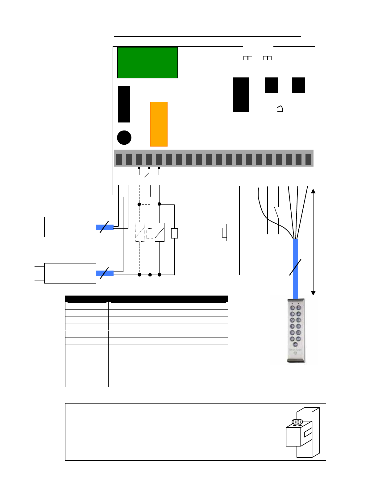
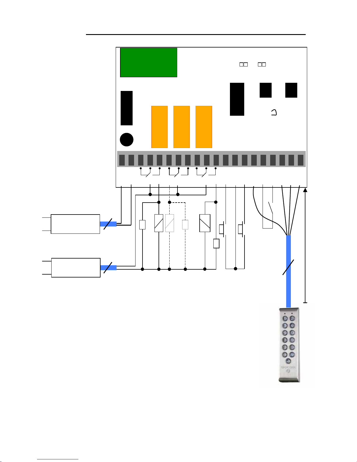
A. DESCRIPTION 1 relay output version
INPUT VOLTAGE 12 – 24 VAC FREE VOLTAGE
INPUT VOLTAGE 12 - 48 VDC FREE VOLTAGE
12-digit back-lit keypad keys
EPROM memory storage
100 Pin code programmables in 4 or 5-digit code
1 relay output N/O & N/C contact 8A/250V
1 programmable master code in 4 or 5-digit
Buzzer audible signal
1 request-to-exit input
P2 jumper: Reset master code and user codes
P3 jumper: modification of individual code by the user
B. DEFAULT VALUES
Illumination time: 10 seconds
Relay release time: 1 second
Code length: 5-digit
Master Code: 12345
Programming mode time: 120 sec
Sub master code for user to reprogram its Pin code (1 relay output version): *, #
C. AUDIBLE SIGNAL
The buzzer indicates different audible signals. It can be turned off by cutting the ST1 wire on the
remote controller (see page 6)
1 short beep Keypad powered
1 long beep data computing in programming or access granted
2 short beeps Enter or Exit from programming
4 short beeps data computing error
D. CODE LENGTH
The master code and the User codes can be of 4 or 5-digit in length.
All the keypad keys can be used to program a code.
The master code and the Pin code can be of 4 or 5-digit code.
The master code CAN NOT be used as a PIN code (User Pin code).
Codes 00000 and 0000 can only be used to delete a user Pin code. To delete a specific User
pin Code replace it by 0000 if code length is 4-digit format or replace it by 00000 if the code
is in 5-digit format.
E. REQUEST-TO-EXIT INPUT
This normally open loop that operates upon activation relay 1 (GALEO, GALEO 2 or GALEO 3) or
relay 2 (GALEO 2 or 3 version). This feature is especially useful when controlling a lock.
P1 input activates relay 1.
P2 input activates relay 2.
(The output can be programmed).
The timer input H if connected allows using the 0 key as a request-to-enter. If the timer
contact is open then the 0 digit key is used for the Pin code and if the contact is closed then
the 0 key is used for the request-to-enter.
F. CONSUMPTION
12VAC: 20mA in stand by, 100mA max all 3 relays activated
24V AC: 10mA in stand by, 50mA max all 3 relays activated
(Lock consumption not included)

Edition 09/2006 G0301FR0270V01
3
WIRING DIAGRAM PROFIL100EC 1 RELAY OUTPUT
V : Varistors
Terminal Description
V Input voltage 12/24 VAC or 12/48 VDC
R1 Contact repos du relais 1
C1 Commun du relais 1
T1 Contact travail du relais 1
P1 Request-to-exit input relay 1
M Common of input
PX Yellow wire request-to-enter Bell button
H Timer Contact
+ White wire keypad
- Brown wire keypad
E Green wire (illumination)
This device comes with a varistor.
The varistor must be connected on the strike terminal (electromagnet…) operated
by the device.
If this product operates more than one strike, each lock should have a varistor.
The varistor controls the overload produced by the strike coil – back emf.
It is recommended to use a separate power supply when using a Shear Lock
Magnet.
Green
Distance 10
meters
maximum
P1
230V
V
Strike fail secure
Input voltage
according to lock
s
p
ecification
2
White
230V 2
P2: Place jumper for reset
P3: Individual Code
modification by user
4
V
Ma
g
net
/
Strike
Fail
safe
V V R1 C1 T1 R2 C2 T2 R3 C3 T3 P1 M P2 Px H H + - E
RL1
P3 P2
ST1
Input voltage
12 to 24 V AC
or
12
to
48
VDC
Brown
Yellow

Edition 09/2006 G0301FR0270V01
4
II. PROGRAMMING
A. RESET MASTER CODE AND DELETE ALL USER CODES
1. Enter the master code twice (12345 default value master code).
2 beeps are emitted to confirm entry in programming mode.
2. Enter *6 to reset the Master Code and the User codes. One beep is emitted. Press
simultaneously on * and # digit keys to reset all memory on the keypad. Wait for two beeps. The
master code is restored to its default value 12345 and all the User codes are deleted from the
keypad. Once the reset is completed then the keypad returns to a stand-by operating mode.
OR
1. Cut the power. Put the jumper on P2.
2. Put the power back. Wait approximately 3 seconds. Two beeps are emitted to confirm reset of
the keypad. Remove P2 jumper. The master code is restored to its default value 12345 and all the
User codes are deleted from the keypad.
B. SETTING CODE LENGTH
1. Enter the master code twice (12345 default value master code). 2 beeps are emitted to
confirm entry in programming mode.
2. Enter *4 to program the code length. One beep is emitted. Enter 4 or 5 for the digit code.
One beep is emitted to confirm programming of the code length.
3. Enter *5 to modify the master code. One beep is emitted. Enter the new 4 or 5-digit master
code. One beep is emitted to confirm programming of the new master code.
Press # to exit from programming mode. 2 beeps are emitted to confirm that the keypad is in
stand-by operating mode.
Master code or user code: 12369
When changing to 4-digit code: Enter 2369
C. CHANGING THE MASTER CODE
The master code is used only to enter in programming mode
1. Enter the master code twice (12345 default value master code).
2 beeps are emitted to confirm entry in programming mode.
2. Enter *5 to modify the master code. One beep is emitted. Enter the new 4 or 5-digit master.
One beep is emitted to confirm that the master code is programmed.
3. Press # to exit from the programming mode. 2 beeps are emitted to confirm that the keypad
is in stand-by operating mode.
D. ADDING USER CODES
Group 1: from user number 00 to user number 99, relay 1
1. Enter the master code twice (12345 default value master code).
Two beeps are emitted to confirm entry in programming.
•To add user codes:
2. To add a user code, enter the user number (from 00 to 99). If the user number is free 1 beep
is emitted, then enter the 4 or 5-digit user code.
Master code Master code
Two beeps
*6
P2
*4
*5

Edition 09/2006 G0301FR0270V01
5
3. To Change a user code enter the user number, 4 beeps are emitted to indicate that user
location is already programmed. Enter a new 4 or 5-digit code. A beep is emitted to confirm the
new user code.
4. To delete a user code enter the user number, 4 beeps are emitted. Enter 00000 in 5-digit
length code or 0000 in 4-digit length code. A beep is emitted to confirm the new user code.
NOTE: If the user code is already programmed or is identical to the master code, then 4
beeps are emitted.
Press # to exit from the programming mode. 2 beeps are emitted to confirm that the keypad is in
stand-by operating mode.
User code list (from user number 00 to 99)
00
25
50
75
01
26
51
76
02
27
52
77
03
28
53
78
04
29
54
79
05
30
55
80
06
31
56
81
07
32
57
82
08
33
58
83
09
34
59
84
10
35
60
85
11
36
61
86
12
37
62
87
13
38
63
88
14
39
64
89
15
40
65
90
16
41
66
91
17
42
67
92
18
43
68
93
19
44
69
94
20
45
70
95
21
46
71
96
22
47
72
97
23
48
73
98
24
49
74
99
E. TIME OUTPUTS
This section allows to program the illumination time and the Relay activation time
1. Enter the master code twice (12345 default value master code).
2 beeps are emitted to confirm entry in programming mode.
2. Enter *0 to program the key-in keypad time and the illumination time. 1 beep is emitted.
Enter the time in 10th of second – 10 for 10 seconds up to 99 for 99 seconds the backlighting
dims 10 seconds after the last keypress or switches off after entering a valid code. Enter 00
for permanent illumination keys. One beep is emitted to validate the time.
3. Enter *1 to program relay 1 output time (door release time). 1 beep is emitted. For a
timed output enter the time in seconds – 01 for 1 second up to 99 for 99 seconds. Enter 00
for a latched output. One beep is emitted to validate the time.
00
to
99
*0
*1

Edition 09/2006 G0301FR0270V01
6
4. Press # to exit from programming mode. 2 beeps are emitted to confirm that the keypad is in
stand-by operating mode.
4 beeps indicate a data computing error.
F. RESET MASTER CODE
On stand-by operating mode, put a jumper on P2. Wait 1 second and then remove the jumper.
One beep is emitted. The master code is restored to its default value 12345 in 5-digit code and
1234 in 4-digit code.
G. CHANGING THE CODE BY THE USER
To authorize a user to modify its own User code put a jumper on P3 (to disable the feature remove
the jumper).
1. Enter the old user code. The relay is activated and a beep is emitted.
2. Enter the 2-digit sub master code (default sub master code A and B).
A beep is emitted to authorize the modification.
3. Enter the new user code. 2 beeps are emitted to confirm the new code.
4. Check the new user code to be sure of the modification.
H. SETTING A SUB MASTER CODE
The Sub Master code allows the user to change its own code without entering in programming
mode. For security reasons the code need to be changed periodically. This feature makes it
easier and faster to change its code.
1. Enter the master code twice (12345 default value master code).
2 beeps are emitted to confirm entry in programming mode.
2. Press *7 to program a sub master code for the user individual Pin code modification. One
beep is emitted. Enter the new 2-digit sub master code. One beep is emitted to confirm
programming of the sub master code.
3. Press # to exit from the programming mode. 2 beeps are emitted to confirm that the keypad
is in stand-by operating mode.
I. AUDIBLE SIGNAL
The audible signal is enabled in programming mode and when the relay is energised after a valid
code.
To enable the audible feedback on a key press:
1. Enter the master code twice (12345 default value master code).
2 beeps are emitted to confirm entry in programming mode.
2. Press * twice. One beep is emitted. Press 0 to disable the audible signal during a keypress.
Press 1 to enable the audible signal during a keypress. One beep confirms the new setting.
4. Press # to exit from programming. 2 beeps are emitted to confirm exit from programming
mode.
P3
*7
**

Edition 09/2006 G0301FR0270V01
7
III. PROCEDURE DE MONTAGE DU PROFIL 100 EC
Drill (bit Ø6MM) the 2 mounting holes (depth minimum = 35MM) and
the wiring access area.
Insert the S5 2 plastic anchors in the holes.
Mount the back plate of the PROFIL 100 EC with the M4x30 screws.
Insert the cable of the PROFIL 100 EC in the wiring access area.
Place the keypad on the back plate top first and then make sure that it
fits on the back plate.
Close the keypad with the DIAX®M5x8 screw and the DIAX spanner.
To mount the remote electronics box, it is suggested to use the
plastic bracket.
Plots de sortie
Correspondances
Terminal
Description
V Input voltage 12/24 VAC or 12/48 VDC
V
I l 12/24 VAC 12/48 VDC
1
2
3
4
R

Edition 09/2006 G0301FR0270V01
8
WIRING DIAGRAM PROFIL100 EC 2 and 3 relay outputs
V : Varistances
P1 P2
230V
V
Strike fail secure
Input voltage
According to lock
s
p
ecifications 2
Green
Brown
White
230V
2
P2: Place jumper for reset
P3: Individual Code
modification by user
Distance
10 meters
maximum
4
V
Magnet / Strike fail safe
V V R1 C1 T1 R2 C2 T2 R3 C3 T3 P1 M P2 Px H H + - E
RL1
P3 P2
ST1
V
RL2
RL3
Input voltage
12 to 24 V AC
or 12 to 48 VDC
Strike fail secure
Yellow

Edition 09/2006 G0301FR0270V01
9
J. OPTIONAL PROFIL100 EC 2 AND 3 RELAY OUTPUTS
Programming instructions are the same as for the KCIN keypad with 1 relay output.
KCIN 2: 2 relay outputs N/O and N/C contacts 8A @ 250V~
Group 1: from user location 00 to user location 59 to activate relay 1
Group 2: from user location 60 to user location 99 to activate relay 2
Release Time of relay 2 enter *2 sub master code enter *8 (default values 1 and 3).
KCIN 3: 3 relay outputs N/O and N/C contacts 8A @ 250V~
Group 1: from user location 00 to user location 59 to activate relay 1
Group 2: from user location 60 to user location 79 to activate relay 2
Group 3: from user location 80 to user location 99 to activate relay 3
Release time for relay 3 enter *3 sub master code enter *9 (default values 4 and 6)
K. Red and Green LEDs’
The red and green LED’s can be powered in 12V DC (resistors are built-in).
Wirings:
Red 2.2K
Green 2.2K
Gray 0V
Orange 12V DC
Pink 12V DC
Light blue 0V
*2
*8
*3
*9
Table of contents
Other CDVI Keypad manuals

CDVI
CDVI Galeo User manual

CDVI
CDVI CAASE User manual

CDVI
CDVI Digicode PROFIL100EC User manual

CDVI
CDVI Galeo User manual

CDVI
CDVI KCIEN User manual

CDVI
CDVI KRYPTO K4 Instruction Manual

CDVI
CDVI KCIEN User manual

CDVI
CDVI GALEO 4.0 - Bluetooth User manual

CDVI
CDVI DGA User manual

CDVI
CDVI GALEOR User manual

CDVI
CDVI Galeo User manual

CDVI
CDVI Galeo User manual

CDVI
CDVI Digicode PROFIL100EC User manual

CDVI
CDVI GALEO 4.0 - Bluetooth User manual

CDVI
CDVI GALEOR User manual

CDVI
CDVI Galeo 2 User manual

CDVI
CDVI KCIN User manual

CDVI
CDVI GALEO/W User manual

CDVI
CDVI SOLAR2R User manual

CDVI
CDVI GALEO 4.0 - Bluetooth User manual