manuals.online logo
Brands
  1. Home
  2. •
  3. Brands
  4. •
  5. injen technology
  6. •
  7. Automobile Accessories
  8. •
  9. injen technology PF2057 User manual

injen technology PF2057 User manual

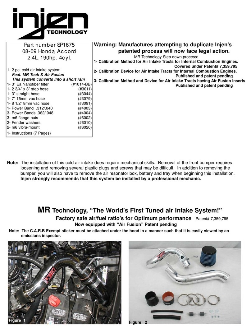
Part number PF2057
2006 Toyota FJ 4.0L V6
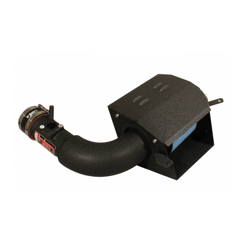
1- MR Tech Power-flow Intake system
1- 8” Inverted top power filter (#1022)
1- Power Box-contents: PB400P-8
1- Powerbox skin plate (A) (#6043)
1- Stabilizer top (B) (#6041)
1- Connecting bottom base (C) (#6042)
1- Top panel pre-filter screen (D) (#6044)
1- 4” velocity stack inlet (E) (#6045)
1- Rect. front pre-filter screen (F) (#6046)
2- main body halfs. (G) (#6048)
4- m6 x 45mm socket head (H) (#6052)
4- m6 x 65mm socket head (I) (#6055)
4- m6 x 12mm socket head (J) (#6056)
1- Power-Box mounting bracket (K) (#20079)
1- 4” straight hose (#3129)
1- 3” straight hose (#3044)
1- 18”- 4mm heater hose (#3104)
2- large Power-Band .462 (.064) (#4006)
2- Power-Band .362 (.048) (#4004)
1- 8mm Vibra- mount (#6062)
1- 8mm flange nut (#6017)
1- 5 page instruction
Note: All parts and accessories are sold
on-line at: “injenonline.com”
Congratulations! You have just purchased the best engineered,
dyno-proven Power-Flow air intake system available.
Please check the contents of this box immediately.
Report any defective or missing parts to the Authorized Injen
Technology dealer you purchased this product from.
Before installing any parts of this system, please read the instructions
thoroughly. If you have any questions regarding installation please
contact the dealer you purchased this product from.
Installation DOES require some mechanical skills. A qualified
mechanic is always recommended.
*Do not attempt to install the intake system while the engine is hot.
The installation may require removal of radiator fluid line that may
be hot.
Injen Technology offers a limited lifetime warranty to the original
purchaser against defects in materials and workmanship. Warranty
claims must be handled through the dealer from which the item was
purchased.
Injen Technology 285 Pioneer Place Pomona, CA 91768 USA
Please check the contents of this box immediately.
Note: This intake system was Dyno-tested with an Injen filter and
Injen parts. The use of any other filter or part will void the
warranty and CARB exemption number. Parts and accessories
are available on line at “Injenonline.com
Note: The installation of this cold air intake does require mechanical skills. Removal of the front bumper requires
loosening and removing several plastic plugs and screws that may be difficult. It is recommended that this
system be installed by a professional mechanic. Be sure to disconnect the negative terminal before proceeding.
Congratulations! You have just purchased the worlds first tuned intake system.
MR Technology, Leading the way!
Patent pending
#1022
(A) and (G)
(B)
(D)
(K)
(E)
Power-Box contents:
POWER-FLOW:An air intake evolution
Tools required:
1- 8mm socket
1- 10mm socket
1- 12mm socket
1- Phillips screw driver
1- 8mm nut driver
1- 55mm allen wrench
1- Disc grinder or Dremel
(C)
(F)
(I)
(H)
(J)
Figure 1
Screw the 8mm vibra-mount into the wheel well
mounting location until the vibra-mount is sitting snug
and flush over the mounting point.
Press the 3” straight hose over the throttle body.
Once the hose has been fitted over the throttle body,
continue to use two power bands over the hose and
tighten the band located over the throttle body.
Loosen and remove the two m8 bolts that secures the
resonator box to the fender well.
align the m8 vibra-mount to the pre-tapped hole located
over the wheel well. It may be necessary to use a
punch to drive a hole through the plastic liner under-
neath when installing the m8 vibra-mount.
Once the cover has been removed, continue to dis-
connect the 4mm vacuum line located behind the air
box cleaner.
Unscrew the two screws from the mass air flow
sensor, continue to remove the mass air flow sensor
from the air box cleaner.
Loosen the two flange nuts on the engine cover (A), then continue to remove the
engine cover off from the intake manifold. Unbolt the m6 bolt located on the
grommet below the air box cleaner (B).
Unbolt the second m6 bolt located on the top of the air box cleaner as shown
above. Removing these two bolt shown in figures one and two will allow you to
remove the entire air box cleaner.
Page 2 of Part# PF2057
The entire air box cleaner and resonator box is now
ready to be removed from the engine compartment. Remove the short 4mm stock vacuum hose from the
fuel pressure regulator. Press the new 18 inch, 4mm
vacuum line over the fuel pressure regulator port.
(A)
(B)
Unplug the crank case breather hose from the air
box cleaner port as shown above.
>>>>>>
>>>>
>>>>
>>>>
Figure 2 Figure 3
Figure 6
Figure 5
Figure 4
Figure 9
Figure 8
Figure 7
Figure 12
Figure 11
Figure 10
An m8 flange nut is used to fasten the power box bracket
to the vibra-mount stud.
Insert the three inch end of the intake into the throttle body hose (A). Once the
3” side has been positioned, continue to insert the 4” end into the power box
straight hose(B).
The intake is now aligned for the best possible fit. Once the intake has been
cleared from any possibility of rubbing, continue to tighten all nuts, bolts and
clamps.
Once the bracket and power box have been assem-
bled, the leg on the bracket will be located on the
radiuses side of the power box.
Press the 4” straight hose over the velocity stack
end. Use the two large power bands over the hose
and tighten the band located over the velocity stack
end.
Loosen and remove the two m6 x 65mm bolts that
secures the velocity stack base to the body. The second 65mm bolt is inserted into base and
body.
Page 3 of Part# PF2057
Align the power box bracket to the holes located on
the base, Use the same m6 x 65mm bolts to fasten
the bracket to the base.
Press the 18” -4mm vacuum line over the 3/16”
intake port as shown above.
Once the Power box is aligned to the intake end,
continue to tighten the flange nut to the vibra-
mount stud.
Lower the assembled power box into the engine
compartment. Insert the upper vibra-mount stud into
the hole located on the bracket.
>>>>
>>>>
>>>>
>>>>
>>>>
>>>>
>>>>
>>>>
>>>>
>>>>
(A)
(B)
>>>>
Figure 15
Figure 14
Figure 13
Figure 18
Figure 17
Figure 16
Figure 20
Figure 19
Figure 23
Figure 22
Figure 21
Rub a dab of light oil around the MAFS O-ring,
then insert it into the sensor adapter. Be careful not
to pinch the O-ring when inserting it into adapter.
The stock breather hose is now aligned to the 5/8” intake
firmly press the hose over the intake port.
Use the stock self tapping screws to secure the MAFS to
the machined sensor adapter. The MAFS and electrical sensor harness have
been installed correctly.
Page 4 of Part# PF2057
You have purchased the Worlds first tuned intake system available anywhere. The Power-Flow intake system features
Injen’s patent pending MR Technology used to tune the intake and Power-Flow box. With Power-Flow, calibrating of the MAF
sensor is not required because the intake system comes tuned for use. Use only Injen replacement filters. The use of any
other filter will change the air/fuel ratio that can cause damage to your engine.
Once the breather hose has been properly installed
over the 5/8” intake port, use the wire tension clamp
to secure the breather hose in place.
Press the electrical sensor harness over the MAFS
until you hear the two devices snap together.
Place the cover in the engine compartment and over the intake. Draw a
line in the area that will be cut in order to get the cover to fit over the intake. Use a grinding wheel , dremel or utility knife to cut the corner section of the
engine cover.
One the engine cover has been fitted and cut along the edge, continue to
install the cover back to its original location and use the stack nuts to secure
the cover in place.
Congratulations! You have just completed the installation of this intake
system. Periodically, we recommend that you check the fitment of the intake
for any shifting of the intake that may cause rattling or rubbing.
>>>>
>>>>
>>>>
>>>>
>>>>
>>>>
Figure 26Figure 25
Figure 24
Figure 29
Figure 28
Figure 27
Figure 31
Figure 30
Figure 33
Figure 32
Assembly and disassembly instructions for the Power Box for the purpose of cleaning screens and filter.
Unbolt the four- 65mm screws from the velocity
stack base located on the corners of the base. Once the screws have been removed, gently pull
the base out of the Power-box body. Unbolt the four- 12mm screws from the velocity
stack base located to the center of the base. Now
separate the base from the velocity stack.
Loosen the clamp on the filter neck in order to
separate the filter and velocity stack. Once the clamp has been loosened, gently
separate the velocity stack from the filter neck. With the velocity stack base out of the way, the
rectangular pre-filter screen will now slide out of the
Power-box channel.
Unbolt the four-45mm screws from the Power-box
top. The screws are located towards the corners of
the top.
Once the screws have been removed separate the
top stabilizer from the Power-Box body. The round pre-filter screen will now detach itself from
the stabilizer top for cleaning.
1. Upon completion of the installation, reconnect the negative battery terminal before you start the engine.
2. Align the entire intake system for the best possible fit. Once the intake has been properly fitted continue
to tighten all nuts, bolts and clamps.
3. Periodically, recheck the alignment of the intake system and make sure there is proper clearance around
and along the length of the intake. Failure to follow proper mainentance procedures may cause
damage to the intake and will void the warranty.
4. Start the engine and listen carefully for any odd noises, rattles and/or air leaks prior to taking it for a test
drive. If any problems arise go back and check the vacuum lines, hoses and clamps that maybe causing
leaks or rattles and correct the problem.
5. Check the filter for excessive dirt build up. Clean or replace the filter with an original Injen filter (can be
bought on-line at “injenonline.com”). Congratulations! You have just completed the installation of the best
intake system sold on the market. Enjoy the added power and performance of your new intake system.
Page 5 of Part# PF2057

Other injen technology Automobile Accessories manuals

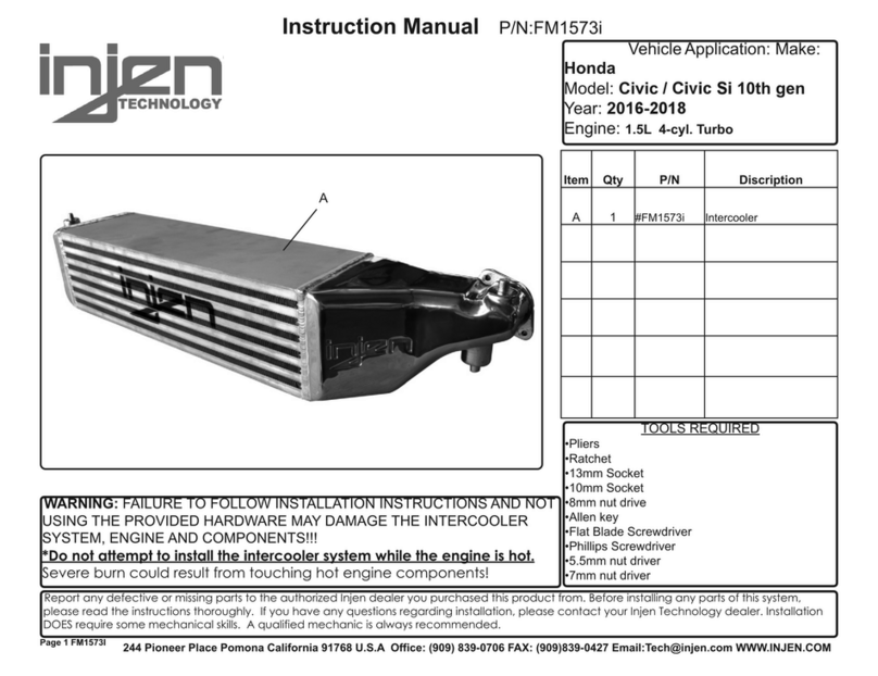
injen technology FM1573i User manual

injen technology

injen technology FM1573i User manual

injen technology SP2115 User manual

injen technology

injen technology SP2115 User manual

injen technology SP1870 User manual

injen technology

injen technology SP1870 User manual

injen technology SP1571 User manual

injen technology

injen technology SP1571 User manual

injen technology SP7035 User manual

injen technology

injen technology SP7035 User manual

injen technology EVO1107 User manual

injen technology

injen technology EVO1107 User manual

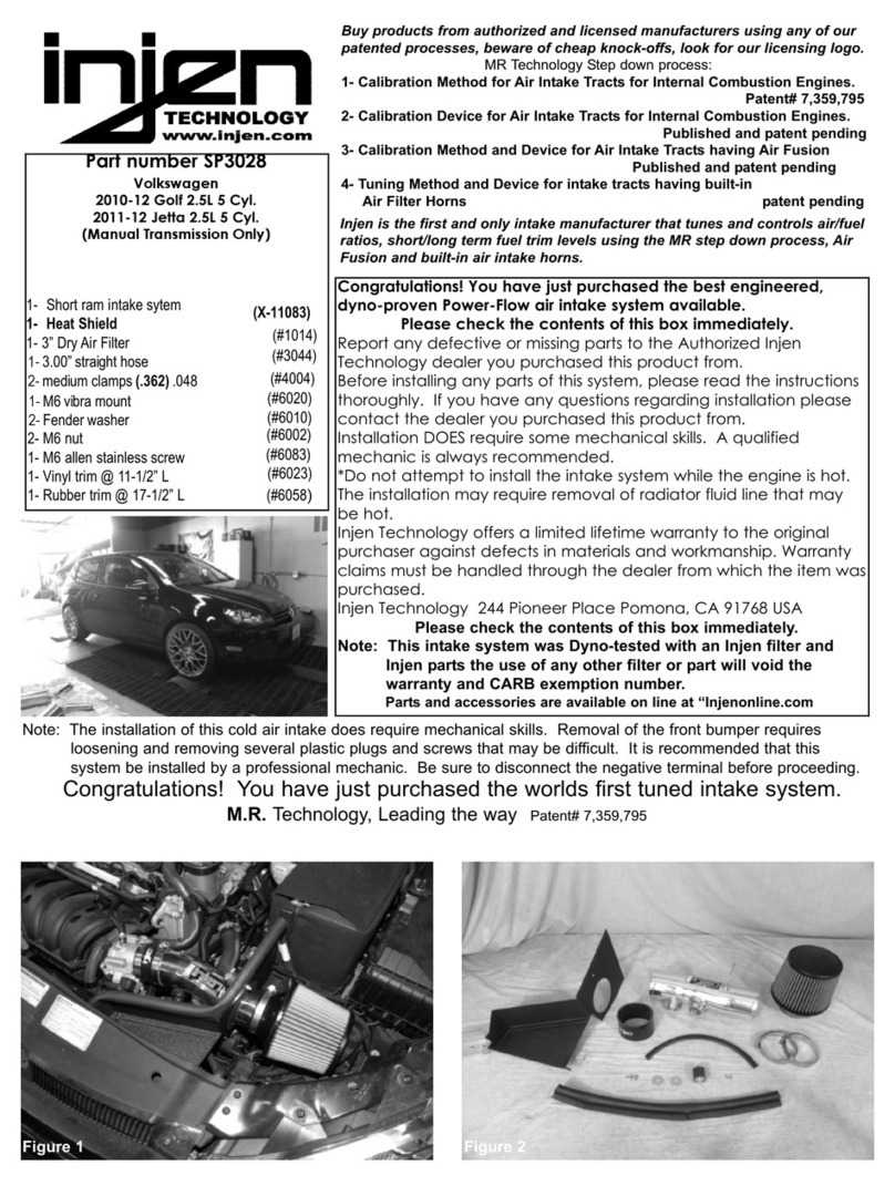
injen technology SP3028 User manual

injen technology

injen technology SP3028 User manual

injen technology RD1482 User manual

injen technology

injen technology RD1482 User manual

injen technology SP1675 User manual

injen technology

injen technology SP1675 User manual

injen technology SP1230 User manual

injen technology

injen technology SP1230 User manual

Popular Automobile Accessories manuals by other brands

Westin 27-1255 installation instructions

Westin

Westin 27-1255 installation instructions

Road Angel Professional user guide

Road Angel

Road Angel Professional user guide

Nokia CK-300 User and installation guide

Nokia

Nokia CK-300 User and installation guide

Allen Sports S104 instructions

Allen Sports

Allen Sports S104 instructions

Tronair 01-1202-0000 Operation & service manual

Tronair

Tronair 01-1202-0000 Operation & service manual

Brodit ProClip 853660 manual

Brodit

Brodit ProClip 853660 manual

NORAUTO MOVING BIKE manual

NORAUTO

NORAUTO MOVING BIKE manual

Whispbar WB751 manual

Whispbar

Whispbar WB751 manual

Whispbar K051W Fitting instructions

Whispbar

Whispbar K051W Fitting instructions

VOLTCRAFT CPS-1500 operating instructions

VOLTCRAFT

VOLTCRAFT CPS-1500 operating instructions

Tronair 01-1109-0010 Operation & service manual

Tronair

Tronair 01-1109-0010 Operation & service manual

Curt Manufacturing 13454 installation instructions

Curt Manufacturing

Curt Manufacturing 13454 installation instructions

Star Headlight & Lantern Mini Phantom ULB9 Installation and instruction manual

Star Headlight & Lantern

Star Headlight & Lantern Mini Phantom ULB9 Installation and instruction manual

Lippert Tire Linc Installation and owner's manual

Lippert

Lippert Tire Linc Installation and owner's manual

Subaru starlink quick guide

Subaru

Subaru starlink quick guide

QA1 5293 Assembly instructions

QA1

QA1 5293 Assembly instructions

Brink 6059 Fitting instructions

Brink

Brink 6059 Fitting instructions

Cruz 923-05 Series Assembly instructions

Cruz

Cruz 923-05 Series Assembly instructions

manuals.online logo
manuals.online logoBrands
  • About & Mission
  • Contact us
  • Privacy Policy
  • Terms and Conditions

Copyright 2025 Manuals.Online. All Rights Reserved.