12
V Ausgänge
Verbraucher
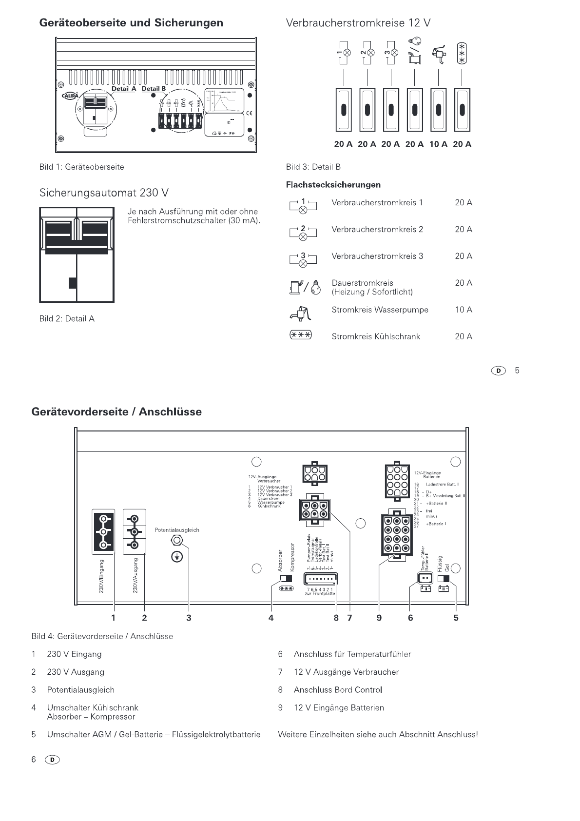
Die Ausgänge
zu
den Verbrauchern (Bild
4,
Pos.
7,
Kontakt 1
bis
3)
führen nur dann +
12
V,
wenn das Verbraucher-Relais
durchgeschaltet hat.
Das
Verbraucher-Relais schaltet erst
durch, wenn +
12
V Steuerspannung am Kontakt
Nr.
4 des
7-poligen Steckers (Bild
4,
Pos.
8)
anliegt. Die Verbraucher-
stromkreise sind
mit
je einer 20 A Sicherung abgesichert.
Heizung und Sofortlicht
Die Heizung und das Sofortlicht werden unabhängig vom Ver-
braucher-Relais versorgt.
Sie
sind am Dauerstrom (Kontakt
4)
angeschlossen und
mit
einer 20 A Sicherung abgesichert.
Wasserpumpe
Die Frischwasserpumpe (Kontakt
5)
wird über das Pumpen-
Relais versorgt. Sie ist
mit
einer 10 A Sicherung abgesichert.
Die
Steuerung dieses Stromkreises erfolgt von Ihrer Bedientafel
über den Kontakt
Nr.
7 des 7-poligen Steckers (Bild
4,
Pos.
8).
Ladevorgang
Ladevorgang Versorgungsbatterie (Batterie
11)
Die Elektroversorgung besitzt einen elektronischen Verpol-
ungsschutz. Nur wenn die Batterie richtig angeschlossen ist
und eine Mindestspannung von 1,5 V anliegt, wird der Lade-
strom freigegeben. Während des Ladevorgangs wird die Bat-
teriespannung ständig über die B+ Messleitung überwacht.
Der Ladevorgang erfolgt gemäß der Ladekennlinie unter ge-
ringster Verlustleistung. (Ladekennlinie siehe Bild
7).
Hauptladephase
(alle Spannungswerte bezogen auf 20
°C
Batterietemperatur)
Ladung
mit
maximalem konstanten Ladestrom bis annähernd
14,4 V Batteriespannung erreicht sind. Sinkt
in
diesem Bereich
der Hauptladephase der Ladestrom bedingt durch den Batte-
rieinnenwiderstand und Leitungswiderstände unter 90 % des
Nennstromes ab, wird die Nachladephase gestartet.
Nachladephase
(alle Spannungswerte bezogen auf 20
°C
Batterietemperatur)
Die Ladespannung wird über eine Zeitdauer von zehn Stunden
bei Gel-Batterien/AGM bzw. vier Stunden bei Flüssigelektro-
lytbatterien konstant auf 14,4 V gehalten. Nach Ablauf dieser
Zeit erfolgt eine Umschaltung
in
die Erhaltungsladephase.
Steigt während dieser Zeit der Strom auf über 90 % des
Nennstromes und sinkt dabei die Batteriespannung für einen
Zeitraum von mehr als 15 Minuten bei Flüssigelektrolytbat-
terien und mehr als zwei Stunden bei Gel- und AGM-Batte-
rien unter 13,2
V,
so erfolgt eine Umschaltung zurück
in
die
Hauptladephase.
Erhaltungsladephase
(alle Spannungswerte bezogen auf 20
°C
Batterietemperatur)
Die Ladespannung ist auf 13,8 V eingestellt. Der Ladestrom
sinkt dabei auf den für die Batterie zur Ausgleichsladung
notwendigen Wert ab. Steigt der Ladestrom bedingt durch
8 ®
Kühlschrank Absorberbetrieb
A
liJ
K Bild
5:
Umschalter (Bild 4,
Pos.
4)
in
Stellung
A-
Absorberbetrieb.
Bei
laufendem
Motor
wird der Kühlschrank über die Licht-
maschine des Fahrzeuges versorgt.
Das
Kühlschrank-Relais
trennt nach Abstellen des Motors den Kühlschrank von der
Versorgungsbatterie.
Die
Ansteuerung erfolgt über die Leitung
vom D+ der Lichtmaschine.
Ein
Betrieb des Kühlschrankes
mit
12
V ist somit nur während der Fahrt möglich.
Bei
Stand-
pausen kann der Kühlschrank nur
mit
Gas
oder Netzspannung
betrieben werden. Eine Entleerung derVersorgungsbatterie
ist somit ausgeschlossen. Dieser Stromkreis (Kontakt
6)
ist mit
einer Sicherung von 20 A abgesichert.
Kühlschrank Kompressorbetrieb
A
[il
K Bild
6:
Umschalter (Bild 4,
Pos.
4)
in
Stellung K- Kompressorbetrieb.
Der Kühlschrank wird über Dauerstrom versorgt, wenn der
Hauptschalter auf der Bedientafel eingeschaltet ist.
® 7
Verbraucher auf seinen Nennwert und sinkt die Batteriespan-
nung für mindestens zwei Minuten unter 13,2
V,
so schaltet
das Gerät wieder
in
die Hauptladephase zurück.
Parallelbetrieb
Wird während der Nachladephase oder der Erhaltungslade-
phase Verbraucherstrom entnommen,
so
wird dieser sofort
nachgeladen.
Ladevorgang Starterbatterie (Batterie
1)
-
Parallelschaltung
Fahrbetrieb
Im
Fahrbetrieb wird die Starterbatterie (Batterie
1)
von der
Lichtmaschine des Kraftfahrzeuges geladen. Solange die
Lichtmaschine läuft und Spannung am D+ Eingang der
Elektroversorgung über 13,7 V ansteigt, werden die Versor-
gungsbatterie und die Starterbatterie parallel geschaltet. Die
Versorgungsbatterie wird nun von der Lichtmaschine
mit
gela-
den. Fällt die Spannung am D+ Eingang der Elektroversorgung
unter 13,2
V,
wird die Parallelschaltung wieder aufgehoben.
Netzbetrieb
(alle Spannungswerte bezogen auf 20
°C
Batterietemperatur)
Bei
230 V Netzanschluss wird die Versorgungsbatterie vorran-
gig geladen. Erreicht die Versorgungsbatterie die Spannung
von 14,3
V,
erfolgt die Parallelschaltung
mit
der Starterbatterie.
Steigt der Ladestrom bedingt durch Verbraucher auf seinen
Nennwert und sinkt die Batteriespannung unter einen Wert
von 13,2
V,
so wird die Parallelschaltung automatisch aufge-
hoben. Die Starterbatterie bleibt somit immer startfähig.
Solarbetrieb
Bei
Anschluss externer Solarzellen wird die Starterbatterie
mitgeladen, wenn die Versorgungsbatterie eine Spannung
von 14,3 V erreicht hat. Fällt die Spannung derVersorgungs-
batterie unter 13,2 V ab, so wird die Parallelschaltung wieder
aufgehoben.