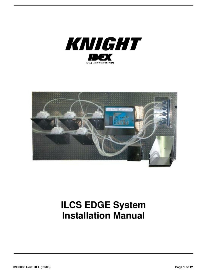
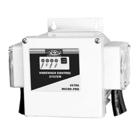
Idex Knight DoseTech DMS User manual

Instrucon Manual
0901048 Rev. C

Page 2 0901048 Rev. C
Table of Contents
Introducon 2
System Control Panel 2
Specicaons 3
Accessory Kit Checklist 3
Installaon Procedures 4
Programming 6
Operaons 11
Troubleshoong 12
Squeeze Tube Replacement 14
Replacement Parts 15
Parts Diagram 16
Wiring Diagram 17
EC - Declaraon of Conformity 18
Mounng Template 22
Warranty Informaon 24
Knight Locaons 24
Introducon
The DoseTech DMS detergent management system is a dispensing system used to transfer precise amounts of pre-soak chemicals into
a pre-wash sink. This chemical dosing system uses an electronically controlled peristalc pump to dispense detergent. Mulple dosing
levels can be programmed to meet specic soil condions for full and half sink levels providing opmal cleaning results prior to
automated decontaminaon steps. The system is comprised of main control/pump unit, water temperature monitor, chemical supply
line with weight and lter, chemical discharge line with check valve and aaching hardware. System is not for use in potenally
explosive environments.
Safety Symbols
Listed below are explanaons of the safety symbols that appear either on the unit, in the instrucon manual, or both. Please
familiarize yourself with the meaning of each symbol.
GENERAL CAUTION: This symbol indicates a general safety cauon.
SHOCK HAZARD: This symbol indicates that hazardous voltages are inside the enclosure.
READ MANUAL: This symbol indicates to read the manual for important instrucons and procedures related to safety.
Safety Precauons
CAUTION: Wear protecve clothing and eye wear whenever operang this system.
CAUTION: Wear protecve clothing and eye wear when dispensing chemicals. Observe safe handling instrucons (MSDS)
provided on chemical container or as supplied by chemical manufacturer.
CAUTION: To avoid severe or fatal shock, physical injury, always disconnect main power when servicing the unit.
•System is for indoor use only
•Do not submerge or place in direct path of spray/moisture
•System operates on safe 24 VDC power
• Only approved, factory authorized technicians to service unit

0901048 Rev. C Page 3
DoseTech DMS Specicaons
Dimensions 6” H x 7” W x 6-1/4” D
15.2 cm x 17.8 cm x 15.9 cm
Case Rang IP-64
Dosing Pump Flow Rate 250 ml/min.
Power Supply / Voltage Wall Mount Type, In: 110-240 VAC 1A 50-60 Hz
Out: 24 VDC 1.67A
Chemical Compability—Dose Pump Industry standard enzymac and other detergents.
Unit Weight 4.3 lbs, 1.95 kg
Temperature Probe Max temperature—257° F, 125° C
DoseTech DMS Accessory Kit Check List
Item No. Part Number Qty. Descripon Check Box*
17020120 1Sucon Cup, 1” OD Vinyl
27901200 1Check Valve, ½ PDI Cracking Pressure, ¼ x ¼ Barb, Viton
30300121 10 Cable Ties
40200009 4Cable Tie Mounts
57020152 4Clamp, Nylon, Snap—.46 Snap
60300519 1Ceramic tube Weight, 3/8 Supply Tube
72201225-EP 1Umbrella Foot Valve
87025841 180 Inches 15 Ft. Tube, T-38 Vinyl, ¼ ID x 3/8 OD (bulk)
97600121 3Mounng Screws and Anchors (sets of two)
10 1600266 1Control Box Cover (Remote Wall Bracket)
*If items are missing from your kit, please contact Knight customer service immediately: 1-800-854-3764. The serial number on your dispenser will be required at
the me of the call.
5
9
1
3
8
10
6
7
4
2

Page 4 0901048 Rev. C
Installation Procedures
1. Tools you will need: drill and drill bit, Phillips screw driver, needle nose pliers, wire cutters, or
something similar to cut tubing and cable ties.
2. To begin the installation of the DoseTech DMS, remove all of the accessories from the included
accessory kit.
3. Remove the faceplate from the DoseTech DMS by removing the screw and pushing up. Attach
the detergent suction tube to the pump as shown in Fig. 1. Use a black nylon clamp to secure
the tube. Replace the faceplate.
4. If you have the time-based option, connect the dispenser discharge tube to the discharge
squeeze tube as shown in Fig 2. Tip: If you soak the end of the tube in hot water for 30 seconds,
it will slide on with less resistance. Use a black nylon clamp to secure the tube.
5. If you have the flow meter option, connect the dispenser discharge tube to the flow meter as
shown in Fig. 3. Use a black nylon clamp to secure the tube. Note: Before connecting the dispenser
discharge tube to the flow meter, run the tube through the black nylon clamp so that it will be
easier to clamp after the tube has been connected to the flow meter. Tip: If you soak the end of
the tube in hot water for 30 seconds, it will slide on with less resistance.
6. Select a place to mount the dispenser. Ensure that it will be mounted within 6’ (1.8m) of a 115
VAC outlet. It is important to keep the cord above the sink level. It is not recommended to use
an extension cord. Verify the dispenser will be mounted within 4’ (1.2m) above the floor, and
no more than 10’ (3m) total distance from the detergent. Note: It is important to mount the
dispenser on a hard, flat surface, that is level. See Fig. 4.
7. Cut out the template on page 22 for mounting the dispenser. Place the template against the
surface that the dispenser will be mounted to. Use the horizontal lines on the template to make
sure the template is level. Tape the template to the wall to secure it in place. Pierce the
template with a sharp pencil to mark where the anchors and screws will go. Remove the
template and pre-drill the holes for the anchors. Insert the anchors and the top two screws.
Make sure to leave enough space between the anchors and the head of the tightened screws
for the key holes on the dispenser to fit. Mount the dispenser by aligning the key holes with the
screws and dropping the dispenser in place. Make sure not to put too much pressure on the
dispenser. Secure the dispenser with the bottom two screws.
8. Route the detergent suction tube to the detergent container. Trim the detergent suction tube
to the proper length after verifying that there is enough tube to reach to the bottom of the
detergent container.
9. Drill or cut a 3/8” hole into the bottle cap of the detergent container and insert the detergent
suction tube through the hole. Slide the ceramic tube weight and umbrella foot valve onto the
detergent suction tube. See Fig 5. Place the cap on the detergent. Push the suction tube to the
bottom of the container. Be sure there are no kinks in the tube or obstructions that would
impede the flow of detergent to the pump..
10. Use the cable e mounts and cable es to secure the detergent sucon tube to
the wall that leads to the dispensing unit. Trim the excess plasc from the cable
es once the detergent sucon tube has been secured. See Fig. 6.
Fig.1
Fig.2
Fig.3
Fig.4
Fig.5

0901048 Rev. C Page 5
11. Route the dispenser discharge tube and temperature probe to the back of the sink
where it will be mounted just above the boom (1-3”), depending on the total
volume of the sink ll. Trim the excess tubing from the dispenser discharge tube
once you have veried the length. Aach the check valve to the end of the
dispenser discharge tube. Make sure that the arrow points in the direcon of the
ow. Use the vinyl sucon cup and cable es to secure the discharge tube and
temperature probe to the inside of the sink. See Fig. 7. Use addional cable es to
secure the dispenser discharge tube to the temperature probe to keep them
together as they go up to the dispenser.
12. Route the power supply cable to the outlet and secure with the cable es. If the
detergent sucon tube and power supply are located on the same side, secure
them together for a cleaner installaon.
13. If mounng the remote control away from the dispenser, you will need to
loosen the strain reliefs on the boom of the dispenser, open the control cover,
cut the zip e, and pull the cables to the length needed (up to 12 feet). Do not
pull on the remote control unit to pull the cables out. Roll up the le over cables
and place them back into the dispenser. Close the control cover and ghten the
strain reliefs. See Fig. 8.
14. Measure the distance between the key holes on the remote wall bracket and
pre-drill the holes for the anchors in the wall. Insert the anchors. Aach the
remote wall bracket with the screws to the anchors. Mount the remote to the
remote wall bracket by sliding it down onto the bracket unl it locks into place.
See Fig. 9.
15. If you will be using the sink top mounng kit, rather than wall mounng the
dispenser, aach the four hex stand o screws to the boom of the dispenser.
Aach the stand base to the hex stand o screws with the four pan head screws.
See Fig 10.
16. If you will be using the foot pedal control (Fig. 11) for hands free dosing, loosen
the strain relief on the boom of the dispenser, insert the wires from the foot
pedal control, remove the remote and open the control cover. Aach the white
wire to the REMOTE START terminal on the barrier strip and the black wire to
the GND terminal on the barrier strip. See Fig. 12. Tighten the strain relief, close
the control cover and aach the remote.
Fig.11 Fig.12
Fig.10
Fig.9
Fig.8
Fig.7
Fig.6
White wire
connecon
Black wire
connecon

Page 6 0901048 Rev. C
Descripon of Screen Display
1.
Power on the unit.
For about 2 seconds you will see the screen to the right.
If the system is equipped with a USB interface, the current USB version will be displayed.
2. Aer about 2 seconds you will see the screen to the right.
3. To enter the programming mode, hold down the ENTER buon unl the display color changes to purple.
4.
Press the UP buon to start/stop priming the detergent. The detergent will ll the detergent will ll the detergent
sucon tube. If the ow meter opon is installed, the ow meter counts will be displayed. The detergent will then ll
the detergent discharge tube. Once there is a steady ow of detergent out of the detergent discharge tube into the
sink, press UP to stop priming.
Important:
1. Check to make sure the roller block is rotang clockwise.
2. Ensure the FLOWMETER CTS has a numerical value. The range of values will vary.
Note: If the ow meter opon is installed and auto prime enabled, when the unit is primed it will use calculaons form
the prime to auto prime the unit when the detergent runs out.
Press ENTER to advance to the next screen.
5.
To access the basic features in the programming mode, you will need a user pass code. To enter a user pass code,
use the SCROLL buon to scroll between digits and the UP and DOWN buons to cycle between 0-9. By default, the
pass code is set to 0000.
Press ENTER to advance to the next screen.
6.
To change the exisng user pass code, use the SCROLL buon to scroll between the digits and use the UP and
DOWN buons to cycle between 0-9.
Press ENTER to advance to the next screen.
7.
To view the reports, there are two opons:
1. Data download (if USB port opon is installed, data will be downloaded to USB sck on coming menu
opons)
2. On-Screen report (data will be displayed directly on LCD)
You can choose either opon by pressing the SCROLL buon. When complete, press ENTER to advance to the next
screen.
Programming DoseTechDMS
USB VERSION
Firmware Ver IXXX
17:05:56AM 08/15/13
LAST DOSE VOLUME 000
LEVELS A&B 025/050
ALARMS TODAY 000
PRESS UP TO START PUMP
PRIMING
PRESS UP TO START PUMP
PRIMING
PRESS SCROLL TO CHANGE
USER CODE
PRESS SCROLL TO CHANGE
USER CODE
SELECT DATA DOWNLOAD OR ON-
SCREEN REPORTS

0901048 Rev. C Page 7
Descripon of Screen Display
8.
To specify date ranges for a report, press the SCROLL buon to scroll between month/date/year, and the UP and
DOWN buons to cycle through the digits.
If no report is necessary, scrolling through the dates is not necessary.
Press ENTER to advance to the next screen
9.
To download the report data (USB port opon required), insert a USB sck into the USB port and press the UP
buon. When the download is complete the screen will display “DONE”. Remove USB sck. This report can then be
viewed with any text editor on a PC. See Fig. 1 on page 13 for an example.
Press ENTER to advance to the next screen.
10.
To access the advanced features in the programming mode, you will need a main pass code. To enter a main pass
code, use the SCROLL buon to scroll between digits and the UP and DOWN buons to cycle between 0-9. By
default, the pass code is set to 0000.
Press ENTER to advance to the next screen.
11.
To access the advanced features in the programming mode, you will need a main pass code. To enter a main pass code,
use the SCROLL buon to scroll between digits and the UP and DOWN buons to cycle between 0-9. By default, the
pass code is set to 0000.
Press ENTER to advance to the next screen.
12.
To change the exisng main pass code, use the SCROLL buon to scroll between the digits and use the UP and
DOWN buons to cycle between 0-9.
If you are not changing the code, press ENTER to advance to the next screen.
13.
To enter a serial number for the dispenser, use the SCROLL buon to scroll between digits and the UP and DOWN
buons to cycle between 0-9.
Press ENTER to advance to the next screen.
14.
To set the me and date, press the SCROLL buon to scroll between hour/minutes/seconds/meridiem/month/
date/year, and the UP and DOWN buons to cycle through the digits.
Note: When entering the me, you must enter it in a 12 hour me format.
15.
To change the language, use the SCROLL buon to toggle between languages.
Press ENTER to advance to the next screen.
ENTER DATE RANGE
TO GET REPORTS
FROM 08-01-13
PRESS UP TO START DATA
DOWNLOAD
TO USB
RUNTIME SCREEN
DISPLAY SELECTION:
LAST DOSE VOLUME YES
DOSAGE COUNTDOWN YES
LEVEL A&B YES
PRESS SCROLL TO
ENTER MAIN CODE
0000
PRESS SCROLL TO CHANGE
USER CODE
PRESS SCROLL TO CHANGE
DATE/TIME
TIME 08:52:06 AM
PRESS SCROLL TO SELECT WHICH
LANGUAGE TO USE
PRESS SCROLL TO
ENTER MAIN CODE
0000

Page 8 0901048 Rev. C
Descripon of Screen Display
16.
To change the units of measure, use the SCROLL buon to toggle between Fahrenheit/Gallons and Celsius/Liter.
Press ENTER to advance to the next screen.
17.
To choose a low level seng, use the SCROLL buon to toggle between N/C and N/O.
Important:
If you are using a ow meter or the me based feature, you have the choice between N/C (normally closed) and N/
O (normally open). The opon you choose should match the low level alarm that you are using.
Press ENTER to advance to the next screen.
18.
To set the alarm sound on or o, use the SCROLL buon toggle to between on and o.
Press ENTER to advance to the next screen.
19.
To set the dispensing volumes, use the SCROLL buon to toggle between volume A and volume B. Use the UP and
DOWN buons to set the numerical value for the amount of detergent you wish to dispense for each volume.
Press ENTER to advance to the next screen.
20.
To set your preferred method of dosing, use the SCROLL buon to toggle between Time Based Dosing and Flow
Metered Dosing.
Press ENTER to advance to the next screen.
21.
If you selected Flow Metered Dosing for the previous step, you will see the auto prime screen. To set auto prime to
on or o, use the SCROLL buon to toggle between on and o. Note: This feature is only available with Flow
Metered Dosing.
Press ENTER to advance to the next screen.
PRESS SCROLL TO
SELECT WHICH UNITS
TO USE
PRESS SCROLL TO SELECT LOW
LEVEL STATE
PRESS SCROLL TO
TURN ALARM SOUND
ON OR OFF
SCROLL TO ENTER
VOLUME A 025 ml
VOLUME B 050 ml
PRESS SCROLL TO
SELECT DOSE MODE
PRESS SCROLL TO
SELECT SCROLL MODE
PRESS SCROLL TO
SELECT WHICH UNITS
TO USE
PRESS SCROLL TO SELECT LOW
LEVEL STATE
PRESS SCROLL TO TURN AUTO
PRIME ON OR OFF

0901048 Rev. C Page 9
Descripon of Screen Display
21.
To calibrate the pump, place the dispensing tube into a 100-200 milliliter graduated cylinder and press the UP
buon. The pump will stop on its own aer dispensing approximately 100 milliliters of detergent and the display
will automacally change to the Entered Captured screen.
22.
To enter the volume captured by the graduated cylinder, use the SCROLL buon to scroll between digits and the UP
and DOWN buons to cycle between 0-9.
Press ENTER to advance to the next screen.
23.
The ow rate for the pump is displayed.
Press ENTER to advance to the next screen.
24. To check for proper calibraon, repeat the pump calibraon steps. The target calibraon volume is 100 mls +/-- 3 mls.
Once you are sased with the calibraon of the pump, press ENTER to advance to the next screen.
25.
To set a temperature range, use the SCROLL buon to toggle between the min range and the max range. Use the
UP and DOWN buons to select a numerical value. Once this range is set, you will have to ensure the sink is lled
with water to meet your minimum seng, but not exceed your maximum. Any variaon below the minimum or
above the maximum will set the alarm o.
Press ENTER to advance to the next screen.
26.
To calibrate the temperature, place a thermometer in the sink lled with water and compare the temperature on
the thermometer and the display of the dispenser. If they are not equal, use the UP and DOWN buons to enter
the correct temperature.
Press ENTER to advance to the next screen.
27.
To turn the temperature hold on or o, use the SCROLL buon to toggle between on and o. If you have
mandatory temperature requirements, you should leave the temperature hold on as this will prevent dosing if the
temperature is not within range.
If no temperature requirements are mandatory, select o and the temperature control with remain o.
Press ENTER to advance to the next screen.
ENTER DATE RANGE
TO GET REPORTS
FROM 08-01-13
PRESS UP TO START DATA
DOWNLOAD
TO USB
RUNTIME SCREEN
DISPLAY SELECTION:
LAST DOSE VOLUME YES
DOSAGE COUNTDOWN YES
LEVEL A&B YES
PRESS SCROLL TO
ENTER MAIN CODE
0000
PRESS SCROLL TO CHANGE
USER CODE
PRESS SCROLL TO CHANGE
DATE/TIME
TIME 08:52:06 AM
PRESS SCROLL TO
ENTER MAIN CODE
0000

Page 10 0901048 Rev. C
Descripon of Screen Display
28.
To clear the usage report data memory, press the SCROLL buon and DOWN buon at the same me. A second
screen will appear asking you “Are you sure?” Press the SCROLL buon and DOWN buon at the same me to
conrm. The screen will display “Done”.
29.
To enter a hospital name, use the SCROLL buon to toggle to between characters, and use the UP and DOWN
buons to select A-Z.
Press ENTER to advance to the next screen.
30.
To enter a department name, use the SCROLL buon to toggle between characters, and use the UP and DOWN
buons to select A-Z.
Press ENTER to advance to the next screen.
31.
To enter a detergent/product name, use the SCROLL buon to toggle between character, and use the UP and DOWN
buons to select A-Z.
Press ENTER to advance to the next screen.
32.
To upload a customized graphic which will be displayed when the dispenser has been in idle, insert USB sck and
press UP to upload. Once upload is complete the screen will display “Done”.
Note: Graphic needs to be 128 x 64 pixels in size, black and white, in a .bmp format, and saved with the lename:
image.bmp.
33.
To change the me for the graphic to display, use the UP and DOWN buons to cycle between 0-9. Enter the
meout in minutes.
Press Enter to advance to next screen.
34.
To set the soak mes for preset A and preset B, use the SCROLL buon to toggle between A and preset B, and use
the UP and DOWN buons to select a numerical value.
Press ENTER to loop back to the rst menu screen.
35. Press and hold ENTER buon to save all of your programming changes. The standard blue screen will appear
nofying you that you have le the programming mode.
PRESS SCROLL AND DOWN TO
CLEAR USAGE DATA MEMORY
ENTER HOSPITAL NAME
ENTER PRODUCT NAME
PRESS UP/DOWN TO
ENTER GRAPHICS
PRESS SCROLL TO
ENTER SOAK TIMER A&B
A <min:sec> 00:20
17:05:56AM 08/15/13
LAST DOSE VOLUME 000
LEVELS A&B 025/050
PRESS UP TO START GRAPHICS
UPLOAD
ENTER DEPARTMENT NAME

0901048 Rev. C Page 11
Descripon of Screen Display
1.
Power on the unit.
For about 2 seconds you will see the screen to the right.
If the system is equipped with a USB interface, the current USB version will be displayed.
2.
If the dispenser has been idle for an extended period of me, the default is an image as shown to the right. The
image is specic to Knight’s product logo unless you have uploaded your own graphic. To uploaded your own
graphic, please refer to step 32 in the programming menu.
To exit the idle mode, press the START buon.
3.
Next you will see the top screen to the right. You are currently in the dispensing runme mode. If the TEMP (F) is
ashing, this means that the temperature is out of range. See troubleshoong secon for soluons if needed.
Level A is the default selecon. To choose between level A or level B, press A or B buon.
Press START to begin dispensing for the selected level. The dispenser will begin pumping in either me-based mode
or ow meter based mode the amount programmed in step 19 of the programming procedures.
4.
To change from the dispensing runme screen to the soak mer runme screen, press the UP or DOWN buon to
toggle between the dispensing runme screen and the soak mer runme screen.
To choose between soak me A and soak me B, press A or B buon.
Press START to begin the countdown of the selected soak mer. The display will show a countdown from the me
programmed in step 34 of the programming procedures.
USB Version
Firmware Ver IXXX
17:05:56AM 08/15/13
LAST DOSE VOLUME 000
LEVELS A&B 025/050
Operang DoseTech DMS
17:05:56AM 08/15/13
LAST DOSE VOLUME 000
LEVELS A&B 025/050
17:05:56AM 08/15/13
LAST DOSE VOLUME 000
LEVELS A&B 025/050
17:05:56AM 08/15/13
LAST DOSE VOLUME 000
LEVELS A&B 025/050

Page 12 0901048 Rev. C
Descripon of Screen Display
If TEMP is ashing on the blue runme screen, the temperature of the water is not within the predened range. Adjust the
water temperature before dispensing.
If TEMP OUT OF RANGE is displayed in green, the temperature of the water is not within the predened range.
If the Chemical empty! Alert is displayed in red, the detergent container is empty and needs to be replaced and the unit re-
primed. Replace the detergent container then press START to begin automac re-prinng.
17:05:56AM 08/15/13
LAST DOSE VOLUME 000
LEVELS A&B 025/050
ALARMS TODAY 000
TEMP OUT OF RANGE
Chemical empty!
Replace Chemical Container,
then press START buon.
DoseTech DMS Runme Alerts
Symptom Soluons/Cause
Temperature Alarm will not shut o
Adjust temperature range
Adjust water temperature
Dosing Alarm will not shut o
Detergent container empty
Recalibrate detergent pump
Detergent discharge tube worn or broken
Can’t access system menus
Reboot the system
User interface switch inoperable
Pump tube broken or worn Replace with factory tube only

0901048 Rev. C Page 13
Dispenser S/N: 0
Report Date: 8/21/2013
From Date: 8/13/2013
To Date: 8/21/2013
Date Time Volume Temperature Events
8/21/2013 8:42:24AM 50 78
8/21/2013 8:42:46AM 50 78
8/21/2013 8:48:38AM 50 77
8/21/2013 8:49:21AM 24 77 Out of Chem.
8/21/2013 8:49:54AM 20 77 Out of Chem.
8/21/2013 8:50:33AM 23 78 Out of Chem.
8/21/2013 8:50:49AM 50 77
8/21/2013 8:51:39AM 50 75 Temp. Error
8/21/2013 8:51:59AM 50 75 Temp. Error
8/21/2013 8:52:43AM 50 77
8/21/2013 8:53:04AM 50 77
8/21/2013 8:53:26AM 50 77
Total Usage: 227.3 Gallons
DoseTech DMS Report Example
Fig. 1

Page 14 0901048 Rev. C
Squeeze Tube Replacement
Removal and Installaon of Front Faceplate
Removal or installaon of the pump faceplate for maintenance purposes should ONLY be performed by qualied and
trained personnel who are considered the Responsible Body for the system.
REMOVAL
IMPORTANT: Unplug the unit before removing the faceplate. To remove the faceplate, remove the screw in the center, then
slide the faceplate up to pull it away from the pump assembly.
INSTALLATION
To install the faceplate, slide the faceplate on the pump assembly and ghten the screw in the center.
The facility operators of the system should NEVER aempt removal or installaon of the pump faceplate and should be
made aware of this by the Responsible Body
Access to internal parts are for Responsible Body (i.e. service personnel).
REPLACING THE SQUEEZE TUBE
1. Purge any chemicals from the sucon and discharge tubes.
2. Remove the faceplate of the pump per the steps shown above.
3. Disconnect the sucon and discharge tubes from pump squeeze tube.
4. Pull the old squeeze tube out of the roller block and remove the barb ngs on each end.
5. Insert the barb ngs into the new squeeze tube and install the new squeeze tube into the roller block.
6. Apply a generous amount of silicone tube lube to the middle third of the tube where the rollers contact it.
7. Re-connect the sucon and discharge tubes to the barbs on the new squeeze tube.

0901048 Rev. C Page 15
Item No. Part No. Qty. Descripon
17010211-LC 1Gear Motor w Cap, 100 RPM
21600265 1Body, Pump, 500 Series
37320195 2Phillips Pan Head #10 Screw, Stainless Steel
47503450 13-Lobe Roller Assembly, Yellow Rollers
57018050 1T-50E, Squeeze Tube, Elasc, 1.
66049024 1Retaining Ring for Pump Tube Barb
76049025 1Barb Fing
80600743 21/8 MNPT X 1/4 Barb Elbow Fing
96204000 1Flow Meter, .4mL, PPS/PPS
10 1900604 2Phillips Pan Head #6 Screw, Stainless Steel
11 1900460 2Phillips Pan Head #6 Screw, Hi-Low, Stainless Steel
12 7225689 1Bracket
13 7020152 1Clamp, Nylon, Snap, .406
14 1900664 2Phillips Pan Head #10 Screw, Stainless Steel
15 1600263 1Pump Shield (Faceplate)
16 1900576 1Phillips Pan Head #4 Screw, Stainless Steel
17 1600266 1Control Box Cover (Remote Wall Bracket)
18 7140817 1Circuit Board Assembly
19 1600708 1Temperature Probe
20 2000519 1Power Supply, 40W, 24VDC, 1.67A, Local Country Power Supply Adapters
21 6049024 1Retaining Ring, Barb (Pump Tube Fing)
22 6049025 1Barb Fing (Pump Tube Sleeve)
23 7020152 1Clamp, Nylon, Snap, .406”
24 7020120 1Sucon Cup, 1” O.D., Vinyl
25 7901200 1Check Valve, 1/2 PSI Cracking Pressure, 1/4” x 1/4” Barb, Viton
26 7025841 1Tube, T-38 Vinyl, 1/4” I.D. x 3/8” O.D., 18” (15.)
27 2201225-EP 1Umbrella Foot Valve
28 0300519 1Ceramic Tube Weight for 3/8” Supply Tube
29 0300121 10 Cable Ties, 3-1/2”
30 0200009 4Cable Tie Mount
31 1201508 1Label with Window
DoseTech DMS Replacement Parts
REPAIR AND SERVICING
Repairs and servicing of the DoseTech DMS are to be performed by factory authorized technicians or the factory only. Contact your
DoseTech DMS supplier for service support.

Page 16 0901048 Rev. C
DoseTech DMS Parts Diagram

0901048 Rev. C Page 17
DoseTech DMS Wiring Diagram

Page 18 0901048 Rev. C

0901048 Rev. C Page 19
Notes

Page 20 0901048 Rev. C
Notes
Table of contents
Other Idex Control System manuals
Popular Control System manuals by other brands

RuiDa
RuiDa RDC644XG user manual

ROL ERGO
ROL ERGO ECS-2 Technical specification

Siemens
Siemens SINUMERIK 828D Turning Function manual

Festo
Festo Checkbox Compact CHB-C-X manual

ORTAL
ORTAL Heat Control System Installation and operation manual

DEEP SEA ELECTRONICS
DEEP SEA ELECTRONICS DSE8610 MKII Operator's manual