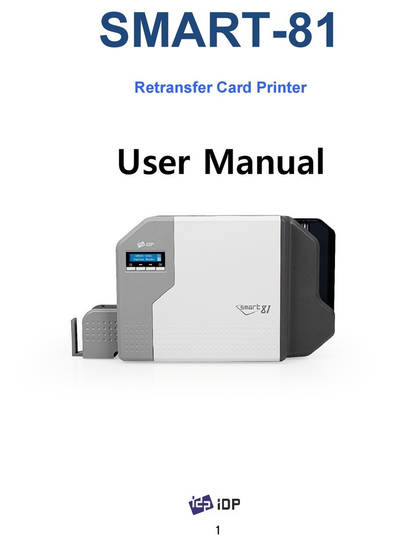
idp SMART-70 User manual

2015.05
SMART-70
User Manual

Copyright Notice
Users must respect the copyright laws applicable in their country. This manual must not be photocopied,
translated, reproduced or transmitted in whole or in part for any reason and by the means that might be, albeit
electronic or mechanical, without the express, written authorization of IDP Corp., LTD.
All information contained herein may be subject to modification without prior notice. IDP Corp., Ltd. accepts no
liability for any possible errors herein, nor for any accidental damage or damage caused through the
dissemination or the use of this manual.
Trademarks
SMART-70 is a trademark and IDP is a registered trademark of IDP Corp., LTD. Windows is registered trademark
of Microsoft Corp. All other trademarks or registered trademarks are marks of their respective holders. SMART-70
Design is a trademark of IDP Corp., Ltd.
Return Materials Authorization
In order to make a warranty claim you must contact an IDP Reseller. You will be responsible for packaging the
printer for shipment and the costs of shipping and insurance of the printer from the point of use of the printer to
the IDP Reseller. The IDP Reseller will bear the costs of shipping and insuring the printer from the repair location
to the address from which the printer was shipped.
Before returning any equipment for in-warranty or out-of warranty repair, contact an IDP Reseller or an IDP
Service Center for a Return Materials Authorization (RMA) number.
Repack the equipment in the original packing material and mark the RMA number clearly on the outside of the
box. For more information about RMA or IDP warranty statements, refer to the Warranty booklet on the quick
install guide.
2

Table of Contents
1. Introduction..............................................................................................................................................................................9
1.1 Overview......................................................................................................................................................................................................9
1.2 Modules .................................................................................................................................................................................................... 11
1.2.1 Input Hopper.................................................................................................................................................................................. 11
1.2.2 Encoding Station .......................................................................................................................................................................... 13
1.2.3 Printer ................................................................................................................................................................................................ 15
1.2.4 Flipper................................................................................................................................................................................................ 20
1.2.5 Laminator ......................................................................................................................................................................................... 21
1.2.6 Output Hopper.............................................................................................................................................................................. 23
1.2.7 Stacker............................................................................................................................................................................................... 24
2. Installation and Operation ............................................................................................................................................ 25
2.1 Hardware installation.......................................................................................................................................................................... 25
2.2 Software installation............................................................................................................................................................................ 44
3. Driver configuration ......................................................................................................................................................... 51
3.1 Printing preferences............................................................................................................................................................................ 51
3.2 Other settings ........................................................................................................................................................................................ 56
4. SMART-70 Utilities ............................................................................................................................................................ 59
4.1 Printer setting......................................................................................................................................................................................... 59
4.2 Printer test ............................................................................................................................................................................................... 67
4.3 Firmware upgrade................................................................................................................................................................................ 71
5. Troubleshooting.................................................................................................................................................................. 74
5.1 Printing quality ...................................................................................................................................................................................... 74
5.2 Card supply ............................................................................................................................................................................................. 75
5.3 Card jam ................................................................................................................................................................................................... 76
5.4 Cleaning.................................................................................................................................................................................................... 84
5.5 TPH replacement .................................................................................................................................................................................. 89
5.6 Laminator Head replacement ......................................................................................................................................................... 91
6. SMART-70 Specifications ............................................................................................................................................... 93
6.1 SMART-70 Input Hopper.................................................................................................................................................................. 93
6.2 SMART-70 Encoding Station........................................................................................................................................................... 93
6.3 SMART-70 Printer................................................................................................................................................................................. 94
6.4 SMART-70 Flipper ................................................................................................................................................................................ 95
6.5 SMART-70 Laminator.......................................................................................................................................................................... 95
6.6 SMART-70 Output Hopper .............................................................................................................................................................. 96
3

Table of Figures
Figure 1 Combination of SMART-70 ..........................................................................................................................................................9
Figure 2 Front side of Input Hopper....................................................................................................................................................... 12
Figure 3 Rear side of Input Hopper ........................................................................................................................................................ 13
Figure 4 Front side of Encoding Station ............................................................................................................................................... 14
Figure 5 Rear side of Encoding Station ................................................................................................................................................. 15
Figure 6 Front side of Printer ..................................................................................................................................................................... 16
Figure 7 Rear side of Printer ....................................................................................................................................................................... 17
Figure 8 Printer control panel .................................................................................................................................................................... 17
Figure 9 Front side of Flipper..................................................................................................................................................................... 20
Figure 10 Rear side of Flipper .................................................................................................................................................................... 20
Figure 11 Front side of Laminator............................................................................................................................................................ 22
Figure 12 Rear side of Laminator ............................................................................................................................................................. 22
Figure 13 Front side of Output Hopper ................................................................................................................................................ 23
Figure 14 Rear side of Output Hopper.................................................................................................................................................. 24
Figure 15 Stacker.............................................................................................................................................................................................. 24
Figure 16 SMART-70 Placement of modules ...................................................................................................................................... 25
Figure 17 Module fastening ........................................................................................................................................................................ 26
Figure 18 Module connection .................................................................................................................................................................... 26
Figure 19 Power connection ....................................................................................................................................................................... 27
Figure 20 Ribbon/film cartridge unlocking .......................................................................................................................................... 27
Figure 21 Pulling out ribbon/film cartridge......................................................................................................................................... 28
Figure 22 Print ribbon/laminating film mounting............................................................................................................................. 28
Figure 23 Print ribbon mounting .............................................................................................................................................................. 29
Figure 24 Laminate film mounting........................................................................................................................................................... 29
Figure 25 Print ribbon/laminating film alignment ............................................................................................................................ 30
Figure 26 Ribbon/film cartridge insertion............................................................................................................................................. 30
Figure 27 Ribbon/Film cartridge locking............................................................................................................................................... 31
Figure 28 Detachment of disposable cleaning roller holder ....................................................................................................... 31
Figure 29 Used disposable cleaning roller removal......................................................................................................................... 32
Figure 30 New disposable cleaning roller mounting ...................................................................................................................... 32
Figure 31 Removal of new disposable cleaning roller protector............................................................................................... 33
Figure 32 Installation of disposable cleaning roller holder.......................................................................................................... 33
Figure 33 Card cartridge release from Input Hopper ..................................................................................................................... 34
Figure 34 Cards thickness adjustment.................................................................................................................................................... 34
4

Figure 35 Card cartridge open................................................................................................................................................................... 35
Figure 36 Removal of the tape for fixing the weight ..................................................................................................................... 35
Figure 37 Card cartridge’s weight fixing ............................................................................................................................................... 36
Figure 38 Card loading .................................................................................................................................................................................. 36
Figure 39 Putting down the card cartridge’s weight....................................................................................................................... 37
Figure 40 Loading card cartridge into Input Hopper...................................................................................................................... 37
Figure 41 Loading card cartridge into Output Hopper.................................................................................................................. 38
Figure 42 Power on ......................................................................................................................................................................................... 38
Figure 43 Module combination checking ............................................................................................................................................. 39
Figure 44 Existing modules combination.............................................................................................................................................. 39
Figure 45 Adjusted modules combination ........................................................................................................................................... 40
Figure 46 Saved module combination ................................................................................................................................................... 40
Figure 47 Completed module combination......................................................................................................................................... 40
Figure 48 System status checking ............................................................................................................................................................ 41
Figure 49 Printer menu.................................................................................................................................................................................. 41
Figure 50 Printer menu (System Config)............................................................................................................................................... 42
Figure 51 Printer menu (Network Config) ............................................................................................................................................ 42
Figure 52 Printer menu (Printer Config) ................................................................................................................................................ 42
Figure 53 Printer menu (Operation) ........................................................................................................................................................ 43
Figure 54 Printer menu (Print Sample)................................................................................................................................................... 43
Figure 55 Sample Card .................................................................................................................................................................................. 43
Figure 56 Printer driver installation 1 ..................................................................................................................................................... 44
Figure 57 Printer driver installation 2 ..................................................................................................................................................... 44
Figure 58 Printer driver installation 3 ..................................................................................................................................................... 44
Figure 59 Printer driver installation 4 ..................................................................................................................................................... 45
Figure 60 Printer driver installation 5 ..................................................................................................................................................... 45
Figure 61 Printer driver installation 6 ..................................................................................................................................................... 45
Figure 62 Printer driver installation 7 ..................................................................................................................................................... 46
Figure 63 Printer driver installation 8 ..................................................................................................................................................... 46
Figure 64 Printer driver installation 9 ..................................................................................................................................................... 46
Figure 65 Printer driver installation 10................................................................................................................................................... 47
Figure 66 Printer driver installation 11................................................................................................................................................... 47
Figure 67 Printer driver installation 12................................................................................................................................................... 47
Figure 68 Printer driver installation 13................................................................................................................................................... 48
Figure 69 Printer driver installation 14................................................................................................................................................... 48
Figure 70 Application installation 1 ......................................................................................................................................................... 48
Figure 71 Application installation 2 ......................................................................................................................................................... 49
5

Figure 72 Application installation 3 ......................................................................................................................................................... 49
Figure 73 Application installation 4 ......................................................................................................................................................... 49
Figure 74 Application installation 5 ......................................................................................................................................................... 50
Figure 75 Application installation 6 ......................................................................................................................................................... 50
Figure 76 Printer properties window....................................................................................................................................................... 51
Figure 77 Layout ............................................................................................................................................................................................... 51
Figure 78 Input / Output settings ............................................................................................................................................................ 53
Figure 79 Printing settings........................................................................................................................................................................... 54
Figure 80 Laminating settings .................................................................................................................................................................... 54
Figure 81 Encoding settings........................................................................................................................................................................ 55
Figure 82 Printer sharing settings............................................................................................................................................................. 56
Figure 83 Ports setting................................................................................................................................................................................... 56
Figure 84 Advanced settings....................................................................................................................................................................... 57
Figure 85 Color Management settings................................................................................................................................................... 57
Figure 86 Security settings........................................................................................................................................................................... 58
Figure 87 Printer status check.................................................................................................................................................................... 58
Figure 88 CardPrinter70Setup Log-in ..................................................................................................................................................... 59
Figure 89 CardPrinter70Setup Start ......................................................................................................................................................... 60
Figure 90 Basic Setup of CardPrinter70Setup..................................................................................................................................... 60
Figure 91 Color density ................................................................................................................................................................................. 62
Figure 92 Resin Black density..................................................................................................................................................................... 62
Figure 93 Overlay density............................................................................................................................................................................. 63
Figure 94 Advanced Setup........................................................................................................................................................................... 64
Figure 95 CardPrinter70Test........................................................................................................................................................................ 67
Figure 96 Monitor ............................................................................................................................................................................................ 68
Figure 97 CardPrinter70Firmware ............................................................................................................................................................. 71
Figure 98 Modules of SMART-70 system (Printer, Flipper) .......................................................................................................... 72
Figure 99 Ready for firmware upgrade.................................................................................................................................................. 72
Figure 100 Manual firmware upgrade .................................................................................................................................................... 73
Figure 101 Printing quality trouble 1...................................................................................................................................................... 74
Figure 102 Printing quality trouble 2...................................................................................................................................................... 74
Figure 103 Printing quality trouble 3...................................................................................................................................................... 74
Figure 104 Printing quality trouble 4...................................................................................................................................................... 75
Figure 105 Printing quality trouble 5...................................................................................................................................................... 75
Figure 106 Card supply problem 1 .......................................................................................................................................................... 75
Figure 107 Card jam in Input Hopper 1 ................................................................................................................................................ 76
Figure 108 Card jam in Input Hopper 2................................................................................................................................................ 76
6

Figure 109 Card jam in Input Hopper 3 ................................................................................................................................................ 76
Figure 110 Card jam in Input Hopper 4 ................................................................................................................................................ 76
Figure 111 Card jam in Input Hopper 5 ................................................................................................................................................ 76
Figure 112 Card jam in Printer 1............................................................................................................................................................... 77
Figure 113 Card jam in Printer 2............................................................................................................................................................... 78
Figure 114 Card jam in Printer 3............................................................................................................................................................... 78
Figure 115 Card jam in Printer 4............................................................................................................................................................... 78
Figure 116 Card jam in Printer 5............................................................................................................................................................... 79
Figure 117 Card jam in Flipper 1 .............................................................................................................................................................. 79
Figure 118 Card jam in Flipper 2 .............................................................................................................................................................. 79
Figure 119 Card jam in Flipper 3 .............................................................................................................................................................. 80
Figure 120 Card jam in Flipper 4 .............................................................................................................................................................. 80
Figure 121 Card jam in Laminator 1 ....................................................................................................................................................... 80
Figure 122 Card jam in Laminator 2 ....................................................................................................................................................... 81
Figure 123 Card jam in Laminator 3 ....................................................................................................................................................... 81
Figure 124 Card jam in Laminator 4 ....................................................................................................................................................... 81
Figure 125 Card jam in Laminator 5 ....................................................................................................................................................... 82
Figure 126 Card jam in Output Hopper 1 ............................................................................................................................................ 82
Figure 127 Card jam in Output Hopper 2 ............................................................................................................................................ 82
Figure 128 Card jam in Output Hopper 3 ............................................................................................................................................ 83
Figure 129 Card jam in Output Hopper 4 ............................................................................................................................................ 83
Figure 130 Card jam in Output Hopper 5 ............................................................................................................................................ 83
Figure 131 Input Hopper cleaning 1 ....................................................................................................................................................... 84
Figure 132 Input Hopper cleaning 2....................................................................................................................................................... 84
Figure 133 Input Hopper cleaning 3....................................................................................................................................................... 84
Figure 134 Input Hopper cleaning 4....................................................................................................................................................... 85
Figure 135 Printer cleaning 1...................................................................................................................................................................... 85
Figure 136 Printer cleaning 2...................................................................................................................................................................... 85
Figure 137 Printer cleaning 3...................................................................................................................................................................... 86
Figure 138 Flipper cleaning 1 ..................................................................................................................................................................... 86
Figure 139 Flipper cleaning 2 ..................................................................................................................................................................... 86
Figure 140 Laminator cleaning 1 .............................................................................................................................................................. 87
Figure 141 Laminator cleaning 2 .............................................................................................................................................................. 87
Figure 142 Laminator cleaning 3 .............................................................................................................................................................. 87
Figure 143 Output Hopper cleaning 1................................................................................................................................................... 88
Figure 144 Output Hopper cleaning 2................................................................................................................................................... 88
Figure 145 Output Hopper cleaning 3................................................................................................................................................... 88
7

Figure 146 TPH replacement 1 .................................................................................................................................................................. 89
Figure 147 TPH replacement 2 .................................................................................................................................................................. 89
Figure 148 TPH replacement 3 .................................................................................................................................................................. 89
Figure 149 TPH replacement 4 .................................................................................................................................................................. 90
Figure 150 TPH replacement 5 .................................................................................................................................................................. 90
Figure 151 TPH replacement 6 .................................................................................................................................................................. 90
Figure 152 Laminator Head replacement 1 ......................................................................................................................................... 91
Figure 153 Laminator Head replacement 2 ......................................................................................................................................... 91
Figure 154 Laminator Head replacement 3 ......................................................................................................................................... 91
Figure 155 Laminator Head replacement 4 ......................................................................................................................................... 92
Figure 156 Laminator Head replacement 5 ......................................................................................................................................... 92
Figure 157 Laminator Head replacement 6 ......................................................................................................................................... 92
8

1. Introduction
1.1 Overview
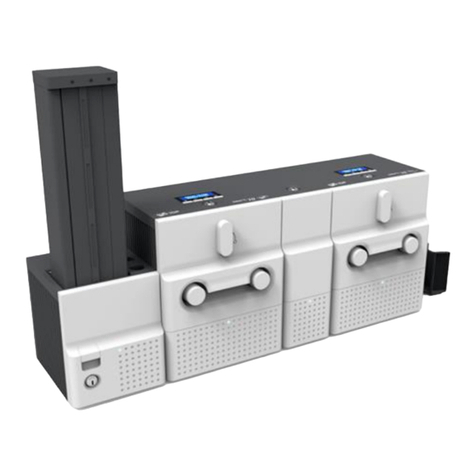
SMART-70 is a high-performance large capacity ID card printer designed by the unique modular
concept that can support various printer configurations to meet different user requirements. 500
cards can continuously be printed, laminated and encoded on various card. SMART-70 consists of
6 different modules (①Input Hopper, ②Encoding station, ③Printer, ④Flipper, ⑤Laminator, ⑥
Output Hopper) that can be configured in various combinations according to different customer
requirements. Required modules can easily be added to extend functions depending on your
needs.
Figure 1 Combination of SMART-70
Key features of SMART-70 are as follows.
Convenience
SMART-70 is sleekly designed, such as modern household appliances, to provide user-
friendly environment with the maximum convenience. Status LED on all modules can
indicate the status of each module at all times. Also, LCD and buttons on Printer and
Laminator are for user to check the status and set the configuration. Card, print ribbon
and other consumables can be changed in intuitive way, and all modules are equipped
①
②
③
⑥
⑤
④
9

with physical locks to provide high security feature.
Clear printing
SMART-70 can print clear images on card by using IDP’s FINE Technology that can
exquisitely control the heat of print head depending on the picture.
High Speed
SMART-70 can print 200 cards/hour for color (YMCKO) and 1,000 cards/hour for
monochrome. Since each module can independently work, multiple cards can be
simultaneously printed, encoded and laminated by the pipeline processing for
enhancing issuance speed.
High Capacity
SMART-70 is designed to support 500 cards capacity in Input Hopper, Printer,
Laminator and Output Hopper. Once card, print ribbon and laminating film are replaced,
500 cards can be continuously issued. Also, cards can be loaded and stacked the up to
3000 cards by using multiple Input / Output Hopper.
Encoding
SMART-70 can encode magnetic stripe and smart cards by using Encoding Station or
the encoding options installed into Printer module. In case of using Encoding station,
magnetic stripe card, contact and contactless smart card can be encoded and 1D & 2D
barcode on card can be scanned. Also, magnetic stripe and contactless smart card
encoder can be installed in Printer module.
Energy Saving
In order to save energy, SMART-70 is designed to minimize unnecessary power
consumption when the system doesn’t work. Since SMART-70 Laminator uses the
instant direct heating mechanism developed by IDP, it requires no warming-up for
laminating and no additional power consumption for maintaining the temperature of
the laminate head while on standby.
Reliability
Since the metal frame, stainless steel shaft and ball bearing is used for the high
durability, SMART-70 can be stably operated under the harsh environments of the
massive issuance environment.
10

Scratch Free
SMART-70 can protect a card surface while the card is in SMART-70 for printing and
encoding. 500 cards can be loaded in Input Hopper but the cards can be taken out
from Input Hopper without scratch by using the patented load distribution structure of
IDP. Also, it is designed that inserted cards don’t get in contact with any other
components except the rollers for card feeding in Printer, Laminator and other module.
In Output Hopper, the stacked cards are lifted up for preventing scratch when a new
card is inserted into Output Hopper.
Software
Since the card design and DB (Database) software for card issuance as well as the
printer driver is provided free of charge, users will not need to purchase additional
software. Utility programs for adjusting the configuration and checking the status of
Printer and powerful SDK (Software Development Kit) for easily developing customized
applications are also provided without coast.
1.2 Modules
SMART-70 can organize the card issuing system by combining the 6 different modules. In this case,
Printer communicates with the PC and controls the other modules. If Laminator is used without
Printer, Laminator will control other modules. This chapter shows the features of each module.
1.2.1 Input Hopper
SMART-70 Input Hopper can be loaded up to 500 cards and supply a card at a time. SMART-70
Input Hopper has the following features.
Cards can be conveniently loaded by using large capacity card cartridge which 500
CR80 cards (card thickness 0.8mm) can be loaded.
The gate of card cartridge can be easily adjusted depending on the thickness of card.
When card cartridge is taken out from Input Hopper, the gate of cartridge is
11

automatically closed for preventing the loss of cards.
In order to prevent the theft of cards, physical locking mechanism can prevent card
cartridge from being taken out from Input Hopper.
For solving the problem caused by dust, both sides of card are cleaned when the card
is supplied.
The cleaning device is easily managed by changing the disposable cleaning roller
included in new print ribbon package whenever print ribbon is changed.
Since cards in cartridge pushed by special structure of IDP’s patented technology, cards
are stably supplied even if the cards are stuck by the static.
500 cards are loaded, but the loaded cards don’t make scratch because the weight of
loaded cards is dispersed when the lowest card has to be supplied.
When card cartridge is empty, Input Hopper can automatically check and notify the
status.
Figure 2 Front side of Input Hopper
1
2
3
①Card cartridge
500 cards can be loaded.
②Disposable cleaning roller holder
Please install the disposable cleaning roller
included with new ribbon.
③Cartridge release button
Please pull up card cartridge while pressing
cartridge release button.
④Indicator LED
The status of Input Hopper is displayed by the
color.
⑤Physical lock
Card cartridge is locked and can’t be taken out
from Input Hopper.
⑥Card gate
Card is supplied to other module.
4
5
6
12

Figure 3 Rear side of Input Hopper
1.2.2 Encoding station (Being developed)
SMART-70 Encoding Station is designed to read barcode printed on card and support various
types of encoding. By using Encoding Station, multiple cards can be simultaneously printed and
encoded to enhance issuance speed.
Various optional encoders can be installed in Encoding Station as below. Optional encoding
modules can be purchased according to your needs.
Barcode reader
1D Barcode: Code32, Code39, Code93, Code128, Codaba, EAN 128, …
2D Barcode: PDF417, MicroPDF417, MaxiCode, DataMatrix, QR Code, …
Magnetic encoder
ISO7811 HiCo / LoCo Card
JIS2 Card
Contact smart card encoder
ISO 7816 A/B/C Card
1
2 3 4 5
①Kensington lock
Kensington lock is usable.
②Communication port
To communicate between SMART-70 modules,
please connect to an adjacent module.
③Serial communication port
This port is used when an external device
controls Input Hopper.
④Power port
Please connect the 24V DC power adaptor
provided with Input Hopper.
⑤Power switch
Turn On/Off
13

ISO 7816 1/2/3/4 microprocessor Cards
Contactless smart card encoder
ISO 14443 A/B Card
Mifare, DESFire Card
ISO 18092(NFC) Card
Felica Card
Figure 4 Front side of Encoding Station
1
2 3
4 5
①Control panel LCD
The status of Encoding Station is displayed.
②Control panel buttons
Buttons are used to check configuration or
status.
③Physical lock
Front cover is locked and can’t be detached.
④Indicator LED
The status of Encoding Station is displayed by
the color.
⑤Card gate
Card gate is to convey cards from module to
module.
14

Figure 5 Rear side of Encoding Station
1.2.3 Printer
SMART-70 Printer is the high-end printer which the IDP’s printing technologies are concentrated.
SMART-70 Printer can continuously print 500 cards of color or 3000 cards of mono, and the
magnetic stripe and contactless encoding option can be installed.
SMART-70 Printer has the following features.
LCD and 4 buttons on the control panel of Printer are for user conveniences and users
can easily check the status of Printer and adjust the configuration.
Indicator LED on the front side of Printer displays the status of Printer by using the
color, so user can intuitionally check the status of Printer.
For improving the convenience of changing print ribbon, ribbon cartridge is designed
as the drawer type and the print ribbon can easily be changed.
By using ribbon cartridge lock lever, ribbon cartridge can easily be locked and print
head can be moved up and down for the convenience of maintenance.
For the prevention of thefts, physical locking mechanism and Kensington lock are
designed and applied to Printer.
Ethernet port is installed by default and user can print and encode cards via network.
①Kensington lock
Kensington lock is usable.
②Communication port
To communicate between SMART-70 modules,
please connect to an adjacent module.
③USB device port
Please connect to the USB host port of Printer
module.
④Power port
Please connect the 24V DC power adaptor
provided with Encoding Station.
⑤Power switch
Turn On/Off.
1
2 3 4 5 2
15

For massive card issuance, metal frame, stainless steel shaft, ball bearing and high
quality materials are used to increase the stability and reliability of Printer.
In order to prevent scratch on cards, Printer is designed that cards don’t get in contact
with any other components except rollers when cards are being fed in Printer.
High printing speed and improved printing algorithm can guarantee a more vivid and
fine printing quality.
Since card design and DB (Database) software for card issuance as well as printer
driver and utility programs are provided free of charge, additional software is not
needed to purchase.
Figure 6 Front side of Printer
1
2 3
5
7
4
6
①Control panel LCD
The status of Printer is displayed.
②Control panel buttons
Buttons are used to adjust configuration and
check status.
③Physical lock
Physical lock is to lock Printer and ribbon
cartridge.
④Ribbon cartridge lock lever
To pull out ribbon cartridge, please turn lever
to the right 90 degrees for taking.
⑤Ribbon cartridge
Color ribbon for 500 cards or mono ribbon for
3000 cards is loaded into ribbon cartridge.
⑥Indicator LED
The status of Printer is displayed by the color.
⑦Card gate
Card gate is to convey cards from module to
module.
16

Figure 7 Rear side of Printer
Control panel of Printer consists of 2 lines LCD and 4 buttons. The 4 buttons have the functions as
shown in the figure 8.
Figure 8 Control panel of Printer
①Kensington lock
Kensington lock is usable.
②Communication port
To communicate between SMART-70 modules,
please connect to an adjacent module.
③Serial communication port
This port is to communicate with external
device except SMART-70 modules.
④Ethernet port
This port is for network communication.
⑤USB host port
This port is for connecting to the USB device
port of Encoding Station.
⑥USB device port
To communicate with PC, please connect to PC.
⑦Power port
Please connect the 24V DC power adaptor
provided with Input Hopper.
⑧Power switch
Turn On/Off.
1
2 3 4 5 2
6 7 8
Menu/Cancel Left/Up Right/Down Select/OK
17

The menus of the control panel of Printer are as below table.
Menu Submenu Description
>System Config.
>>Combination To set module combination. Refer to
the chapter
2.1.10 for modules combination setting.
>>Operation Mode To set Printer as a Master device. Default is Master.
>>Insert Dir To set the direction of Card In. Default is the left.
>>Eject Dir To set the direction of Card Out. Default is the right.
>>Auto Card In
To set the automatic card feeding when the card is
detected at the direction of Card In. Default is OFF.
>>UserCounterClear To reset user issue count.
>Network Config.
>>DHCP To set whether to use DHCP function. Default is On.
>>IP Address IP address to be used when DHCP is OFF.
>>Network Mask Network Mask to be used when DHCP is OFF.
>>Gateway Gateway address to be used when DHCP is OFF.
>Print Config.
>>XStartPosition To set the start position of the printing on the card’s
X-axis (shorter side).
>>YStartPosition To set the start position of the printing on the card’s
Y-axis (longer side).
>>YEndPosition To set the
end position of the printing on the card’s
Y-axis.
>>YScale To s e t the length of printed image on the card’s Y-
axis.
>>TotalDensity To set the total printing density.
>>ColorDensity To set the color density
>>BlackDensity To set the resin black density.
>>OverlayDensity To set overlay density.
18

>>RMP+ To adjust the force for pulling print ribbon during
printing when the residual quantity of print ribbon is
in its maximum quantity.
>>RMP- To adjust the force for pulling print ribbon during
printing when the residual quantity of print ribbon is
in its minimum quantity.
>>RMM+ To adjust the force for pulling print ribbon during
alignment when the residual quantity of print ribbon
is in its maximum quantity.
>>RMM- To adjust the force for pulling print ribbon during
alignment when the residual quantity of print ribbon
is in its minimum quantity.
>>HeadResister To set resistance value of TPH (Thermal Print Head).
>Operation >>Print Sample To print a sample card.
>Information
>>Printer Serial To show the serial number of Printer.
>>Firmware Ver. To show the firmware version of Printer.
>>Head Serial To show the serial number of TPH.
>>Ribbon Balance To show the print ribbon type and balance.
>>IP Address To show the current IP address of Printer.
>>Network Mask To show the current Network mask of Printer.
>>Gateway To show the current Gateway of Printer.
>>MAC Address To show the MAC address of Printer.
>>User Count To show the number of issued cards that user can
reset.
>>Factory Count To show the number of accumulated issued cards
after factory shipment.
19

1.2.4 Flipper
SMART-70 Flipper can flip over a card for dual sided printing and laminating. The error card bin in
Flipper can collect 30 error cards (encoding failed cards) and the collected cards can be taken out
by opening the front cover of Flipper.
Figure 9 Front side of Flipper
Figure 10 Rear side of Flipper
①Kensington lock
Kensington lock is usable.
②Communication port
To communicate between SMART-70 modules,
please connect to an adjacent module.
③Power port
Please connect the 24V DC power adaptor
provided with Flipper.
④Power switch
Turn On/Off
1
2
3
①Physical Lock
Physical lock is to lock Flipper cover.
②Flipper cover
To take out error cards or fix problem, please
open Flipper cover by pulling out.
③Indicator LED
The status of Flipper is displayed by the color.
④Card gate
Card gate is to convey cards from module to
module.
4
1
2 3 4 2
20
Other manuals for SMART-70
1
Table of contents
Other idp Printer manuals

