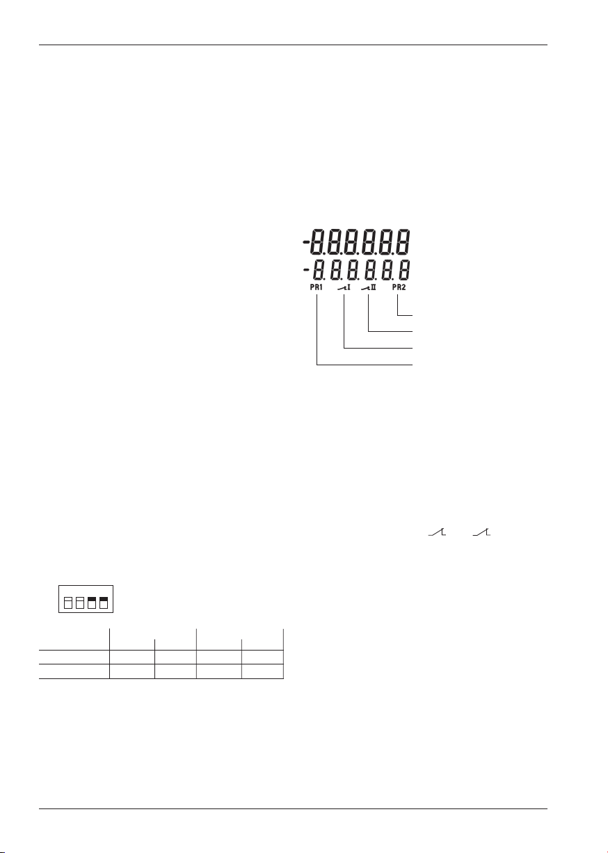
VORWAHLZÄHLER E89005
SEITE 5
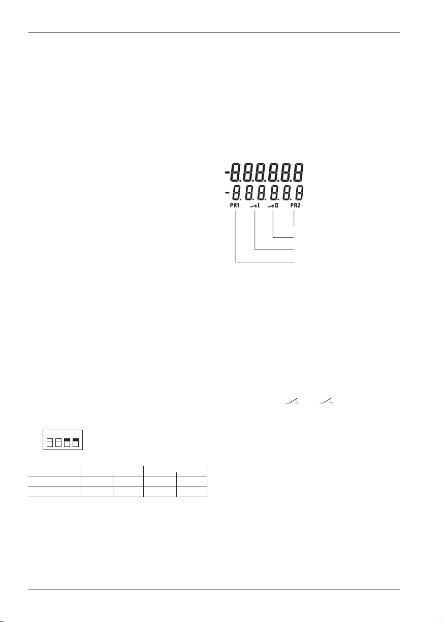
Betriebsart Add:
Zähler arbeitet addierend
Dauersignale bei Zählerstand >
Vorwahl 1 und Zählerstand >Vor-
wahl 2
Wischsignale bei Zählerstand =
Vorwahl 1 und Zählerstand = Vor-
wahl 2 Reset auf Null
Betriebsart Sub.
Zähler arbeitet subtrahierend
Dauersignale bei Zählerstand <Vor-
wahl 1 und Zählerstand <Null
Wischsignale bei Zählerstand =Vor-
wahl 1und Zählerstand = Null
Reset auf Vorwahl 2
Betriebsart AddAr:
Zähler arbeitet addierend
Dauersignal bei Zählerstand >Vor-
wahl 1 oder Wischsignale bei
Zählerstand = Vorwahl 1 und
Zählerstand = Vorwahl 2
automatisches Nullsetzen.
Betriebsart SubAr:
Zähler arbeitet subtrahierend
Dauersignale bei Zählerstand <
Vorwahl 1 oder Wischsignale bei
Zählerstand = Vorwahl 1 und
Zählerstand = Null
autom. Setzen auf Vorwahl 2
Betriebsart AddbAt:
Zähler arbeitet addierend
Wischsignal bei Zählerstand = Vor-
wahl 2 und automatisches Nullset-
zen. Ein zweiter addierender Vor-
wahlzähler (batch-counter = Schlei-
fenzähler), eingestellt auf Vorwahl
1, zählt die Anzahl der autom. Wie-
derholungen von Vorwahl 2
Dauersignal bei Zählerstand >Vor-
wahl 1 oder Wischsignal bei Zähler-
stand = Vorwahl 1. Die Resettaste
setzt beide Zähler auf Null, der
Reset-Eingang nur den Zeitzähler
Betriebsart SubbAt:
Zähler arbeitet subtrahierend
Wischsignal bei Zählerstand = Null
und automatisches Setzen auf Vor-
wahl 2.
Schleifenzähler wie Betriebsart
AddbAt. Die Resettaste setzt den
Zeitzähler auf Vorwahl 2 und den
Schleifenzähler auf Null, der Reset-
Eingang nur den Zeitzähler auf Vor-
wahl 2
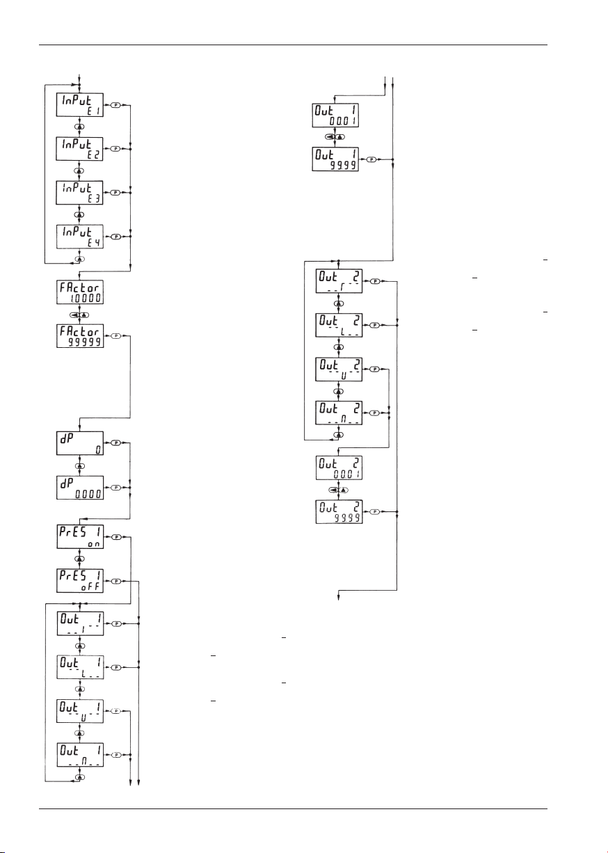
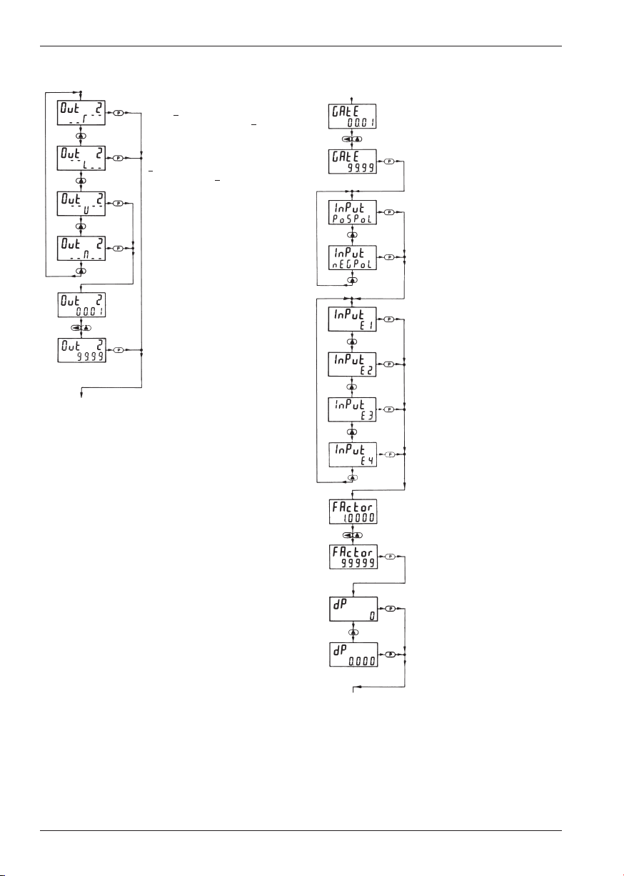
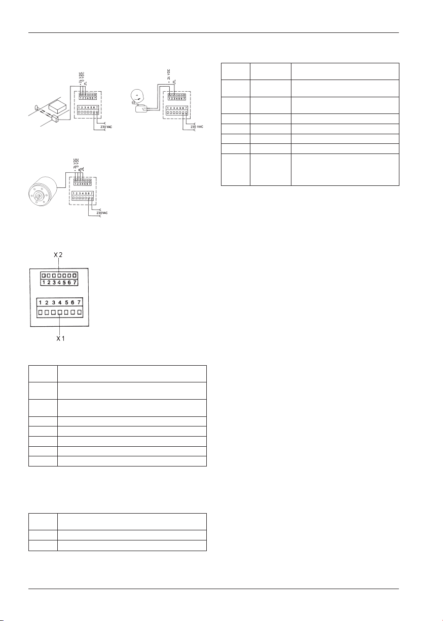
Polarität der Eingänge
pospol: positive Polarität (PNP)
nach + 24 V schaltend
negpol: negative Polarität (NPN)
nach 0 V schaltend
Zeiteinheit:
Zählung in s; 0,1 s; 0,01 s oder
0,001 s*
Zählung in min; 0,1 min; 0,01 min
oder 0,001 min*
Zählung in h; 0,1h; 0,01h oder
0,001 h*
* je nach Stellung des Dezimal-
punktes
Zählung in h:min:s
Dezimalpunkt (Auflösung)
0 = keine Dezimalstelle
0,0 = 1 Dezimalstelle
0,00 = 2 Dezimalstellen
0,000 = 3 Dezimalstellen
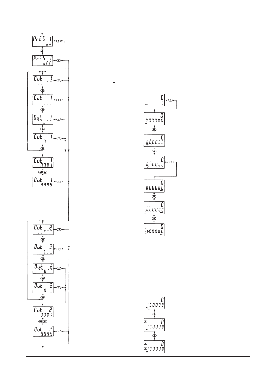
Vorwahl 1 ein- oder ausschalten
on = EIN
oFF = AUS
Dauersignal von Ausgang 1,
wird bei add. Zählung bei Zähler-
stand >Vorwahl 1 und bei subtr.
Zählung bei Zählerstand <Vorwahl 1
aktiv *
Dauersignal von Ausgang 1,
wird bei add. Zählung bei Zähler-
stand >Vorwahl 1 und bei subtr.
Zählung bei Zählerstand <Vorwahl 1
passiv**
Wischsignal von Ausgang 1,
wird bei Zählerstand = Vorwahl 1
passiv**
Wischsignal von Ausgang 1,
wird bei Zählerstand = Vorwahl 1
aktiv*
Dauer des Wischsignals von Aus-
gang 1, einstellbar von 00,01 s bis
99,99 s
* Relaisspule wird bei Erreichen
des Vorwahlwertes angesteuert
** Relaisspule wird bei Erreichen
des Vorwahlwertes spannungslos.
6.2.2 Programmierroutine Zeitzähler