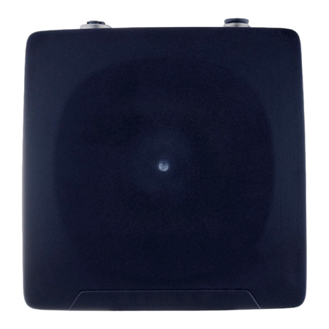
IFM JD Application guide

Device manual
Inclination sensor JD
with CANopen interface
80279676/00 12/2020
UK

2
Contents
1 Preliminary note � � � � � � � � � � � � � � � � � � � � � � � � � � � � � � � � � � � � � � � � � � � � � � � � � 4
1�1 Explanation of symbols � � � � � � � � � � � � � � � � � � � � � � � � � � � � � � � � � � � � � � � 4
2 Safety instructions � � � � � � � � � � � � � � � � � � � � � � � � � � � � � � � � � � � � � � � � � � � � � � � 5
3 Functions and features � � � � � � � � � � � � � � � � � � � � � � � � � � � � � � � � � � � � � � � � � � � 5
4 Installation � � � � � � � � � � � � � � � � � � � � � � � � � � � � � � � � � � � � � � � � � � � � � � � � � � � � � 6
4�1 Fixing the sensor � � � � � � � � � � � � � � � � � � � � � � � � � � � � � � � � � � � � � � � � � � � � 6
5 Electrical connection� � � � � � � � � � � � � � � � � � � � � � � � � � � � � � � � � � � � � � � � � � � � � � 6
5�1 Bus termination � � � � � � � � � � � � � � � � � � � � � � � � � � � � � � � � � � � � � � � � � � � � � 6
6 CANopen interface � � � � � � � � � � � � � � � � � � � � � � � � � � � � � � � � � � � � � � � � � � � � � � � 7
6�1 CANopen functions � � � � � � � � � � � � � � � � � � � � � � � � � � � � � � � � � � � � � � � � � � 8
6�1�1 Pre-operational � � � � � � � � � � � � � � � � � � � � � � � � � � � � � � � � � � � � � � � � � 8
6�1�2 Operational Mode � � � � � � � � � � � � � � � � � � � � � � � � � � � � � � � � � � � � � � � 9
6�1�3 Stopped mode � � � � � � � � � � � � � � � � � � � � � � � � � � � � � � � � � � � � � � � � � � 9
6�1�4 Re-initialisation of the inclination sensor � � � � � � � � � � � � � � � � � � � � � 10
6�2 Boot-up procedure � � � � � � � � � � � � � � � � � � � � � � � � � � � � � � � � � � � � � � � � � � 10
6�3 Usage of the Layer Settings Service (LSS) � � � � � � � � � � � � � � � � � � � � � � � �11
7 Status LED � � � � � � � � � � � � � � � � � � � � � � � � � � � � � � � � � � � � � � � � � � � � � � � � � � � � 12
8 Measurement axes � � � � � � � � � � � � � � � � � � � � � � � � � � � � � � � � � � � � � � � � � � � � � � 12
8�1 Dual axis inclination sensor ± 90° � � � � � � � � � � � � � � � � � � � � � � � � � � � � � � 12
8�2 Single axis inclination sensor ± 0���360°� � � � � � � � � � � � � � � � � � � � � � � � � � 13
8�3 Default Factory Settings � � � � � � � � � � � � � � � � � � � � � � � � � � � � � � � � � � � � � � 13
8�4 Active Programming Objects � � � � � � � � � � � � � � � � � � � � � � � � � � � � � � � � � � 14
8�5 Programmable parameters� � � � � � � � � � � � � � � � � � � � � � � � � � � � � � � � � � � � 14
8�6 Command description � � � � � � � � � � � � � � � � � � � � � � � � � � � � � � � � � � � � � � � 14
8�7 Data length of commands � � � � � � � � � � � � � � � � � � � � � � � � � � � � � � � � � � � � 14
8�8 Frequently Used Commands � � � � � � � � � � � � � � � � � � � � � � � � � � � � � � � � � � 15
8�9 PDO Transmission � � � � � � � � � � � � � � � � � � � � � � � � � � � � � � � � � � � � � � � � � � 16
8�9�1 Object 1800h - 1st Transmit PDO Communication Parameter � � � � 16
8�9�2 Object 1801h - 2nd Transmit PDO Communication Parameter � � � � 17
8�9�3 Transmission mode � � � � � � � � � � � � � � � � � � � � � � � � � � � � � � � � � � � � � 18
8�9�4 Inhibit time � � � � � � � � � � � � � � � � � � � � � � � � � � � � � � � � � � � � � � � � � � � � 18
8�9�5 Event timer� � � � � � � � � � � � � � � � � � � � � � � � � � � � � � � � � � � � � � � � � � � � 18
8�9�6 Cyclic timer� � � � � � � � � � � � � � � � � � � � � � � � � � � � � � � � � � � � � � � � � � � � 19
8�9�7 Object 1A00h - 1st Transmit PDO Mapping Parameter � � � � � � � � � � 19
8�9�8 Object 1A01h - 2nd Transmit PDO Mapping Parameter � � � � � � � � � 19
8�9�9 Types of SDO� � � � � � � � � � � � � � � � � � � � � � � � � � � � � � � � � � � � � � � � � � 21
9 Object directory (OD) � � � � � � � � � � � � � � � � � � � � � � � � � � � � � � � � � � � � � � � � � � � � 22
9�1 Object 1000h - Device Type � � � � � � � � � � � � � � � � � � � � � � � � � � � � � � � � � � � 22
9�2 Object 1001h - Error Register � � � � � � � � � � � � � � � � � � � � � � � � � � � � � � � � � 22
9�3 Object 1003h - pre-defined error field � � � � � � � � � � � � � � � � � � � � � � � � � � � 22
9�4 Object 1005h - COB-ID Sync � � � � � � � � � � � � � � � � � � � � � � � � � � � � � � � � � � 23

UK
3
9�5 Object 1008h - Manufacturer Device Name � � � � � � � � � � � � � � � � � � � � � � � 23
9�6 Object 1009h - Manufacturer Hardware Version � � � � � � � � � � � � � � � � � � � 23
9�7 Object 100Ah - Manufacturer Software Version � � � � � � � � � � � � � � � � � � � � 23
9�8 Object 100Ch - Guard Time � � � � � � � � � � � � � � � � � � � � � � � � � � � � � � � � � � � 23
9�9 Object 100Dh - Life Time Factor � � � � � � � � � � � � � � � � � � � � � � � � � � � � � � � 23
9�10 Object 1010h - Store Parameters� � � � � � � � � � � � � � � � � � � � � � � � � � � � � � 24
9�11 Object 1011h - Restore Parameters � � � � � � � � � � � � � � � � � � � � � � � � � � � � 24
9�12 Object 1014h - COB-ID Emergency � � � � � � � � � � � � � � � � � � � � � � � � � � � � 25
9�13 Object 1016h - Consumer Heartbeat Time� � � � � � � � � � � � � � � � � � � � � � � 25
9�14 Object 1017h - Producer Heartbeat Time� � � � � � � � � � � � � � � � � � � � � � � � 25
9�15 Object 1018 - Identity Object � � � � � � � � � � � � � � � � � � � � � � � � � � � � � � � � � 25
9�16 Object 2200h - Cyclic Timer � � � � � � � � � � � � � � � � � � � � � � � � � � � � � � � � � � 25
9�17 Object 2300h - Save Parameter with Reset � � � � � � � � � � � � � � � � � � � � � � 26
9�18 Object 2600h - Preset X-Axis (± 90º Version) / Preset (360º Version) � � 26
9�19 Object 2601h - Preset Y axis � � � � � � � � � � � � � � � � � � � � � � � � � � � � � � � � � 26
9�20 Object 2700h Fast Bootup Enable � � � � � � � � � � � � � � � � � � � � � � � � � � � � � 26
9�21 Object 3000h - Node Number � � � � � � � � � � � � � � � � � � � � � � � � � � � � � � � � 27
9�21�1 Programming example (for NN=1): Set Node Number (NN) to 50
Decimal (32h)� � � � � � � � � � � � � � � � � � � � � � � � � � � � � � � � � � � � � � � � � � � � � � � 27
9�22 Object 3001h - Baud rate � � � � � � � � � � � � � � � � � � � � � � � � � � � � � � � � � � � � 27
9�23 Object 3002h - Termination Resistor � � � � � � � � � � � � � � � � � � � � � � � � � � � 28
9�24 Object 3005h - Auto BootUp Enable � � � � � � � � � � � � � � � � � � � � � � � � � � � 29
9�25 Object 3100h - Moving Average Filter (MAF) � � � � � � � � � � � � � � � � � � � � � 30
9�26 Gyroscope signal � � � � � � � � � � � � � � � � � � � � � � � � � � � � � � � � � � � � � � � � � � 30
9�27 Object 3400h - Gyro x axis 16 � � � � � � � � � � � � � � � � � � � � � � � � � � � � � � � � 30
9�28 Object 3401h - Gyro y axis 16 � � � � � � � � � � � � � � � � � � � � � � � � � � � � � � � � 30
9�29 Object 3402h - Gyro z axis 16 � � � � � � � � � � � � � � � � � � � � � � � � � � � � � � � � 30
9�30 Accelerometer signal � � � � � � � � � � � � � � � � � � � � � � � � � � � � � � � � � � � � � � � 30
9�31 Object 3403h - Acceleration x axis 16 � � � � � � � � � � � � � � � � � � � � � � � � � � 31
9�32 Object 3404h - Acceleration y axis 16 � � � � � � � � � � � � � � � � � � � � � � � � � � 31
9�33 Object 3405h - Acceleration z axis 16 � � � � � � � � � � � � � � � � � � � � � � � � � � 31
9�34 Object 3411h - Temperature Gyro � � � � � � � � � � � � � � � � � � � � � � � � � � � � � 31
9�35 Object 6000h - Resolution � � � � � � � � � � � � � � � � � � � � � � � � � � � � � � � � � � � 31
9�36 Object 6010h - Slope Long16� � � � � � � � � � � � � � � � � � � � � � � � � � � � � � � � � 32
9�36�1 Calculation of position / slope value from CANopen readout� � � � � 32
9�37 Object 6011h - Slope Long16 Operating Parameter � � � � � � � � � � � � � � � 32
9�37�1 Calculation of the position value based on the operating parameter
� � � � � � � � � � � � � � � � � � � � � � � � � � � � � � � � � � � � � � � � � � � � � � � � � � � � � � � � � � 33
9�38 Object 6012h - Slope Long16 Preset Value � � � � � � � � � � � � � � � � � � � � � � 33
9�39 Object 6013h - Slope Long16 Offset � � � � � � � � � � � � � � � � � � � � � � � � � � � 34
9�39�1 Calculation of Slope Long16 Offset � � � � � � � � � � � � � � � � � � � � � � � � 34
9�40 Object 6014h - Differential Slope Long16 Offset � � � � � � � � � � � � � � � � � � 34
9�41 Object 6020h - Slope Lateral16 � � � � � � � � � � � � � � � � � � � � � � � � � � � � � � � 35
9�41�1 Calculation of position / slope value from CANopen readout� � � � � 35
9�42 Object 6021h - Slope Lateral16 Operating Parameter � � � � � � � � � � � � � � 35

4
1 Preliminary note
Technical data, approvals, accessories and further information at
www�ifm�com�
1.1 Explanation of symbols
►Instructions
> Reaction, result
[…] Designation of keys, buttons or indications
→Cross-reference
Important note
Non-compliance may result in malfunction or interference�
Information
Supplementary note
9�42�1 Calculation of position value based on the operating parameter � � 36
9�43 Object 6022h - Slope Lateral16 Preset Value � � � � � � � � � � � � � � � � � � � � 36
9�44 Object 6023h - Slope Lateral16 Offset � � � � � � � � � � � � � � � � � � � � � � � � � 37
9�44�1 Calculation of Slope Lateral16 Offset� � � � � � � � � � � � � � � � � � � � � � � 37
9�45 Object 6024h - Differential Slope Lateral16 Offset � � � � � � � � � � � � � � � � � 37
9�46 Object 6114h - Differential Slope Long32 Offset � � � � � � � � � � � � � � � � � � 37
10 Object overview � � � � � � � � � � � � � � � � � � � � � � � � � � � � � � � � � � � � � � � � � � � � � � � 38
11 Maintenance, repair and disposal � � � � � � � � � � � � � � � � � � � � � � � � � � � � � � � � � � 40
12 Approvals/standards � � � � � � � � � � � � � � � � � � � � � � � � � � � � � � � � � � � � � � � � � � � � 40
13 Graphic representation of the output functions � � � � � � � � � � � � � � � � � � � � � � � 40
13�1 CANopen Output Values JD11xx � � � � � � � � � � � � � � � � � � � � � � � � � � � � � � 40
13�2 CANopen output values JD21xx (X-axis) � � � � � � � � � � � � � � � � � � � � � � � � 41
13�3 CANopen output values JD21xx (Y-axis) � � � � � � � � � � � � � � � � � � � � � � � � 41
13�4 Output Graphs with Preset and Offset � � � � � � � � � � � � � � � � � � � � � � � � � � 42

UK
5
2 Safety instructions
●Read this document before setting up the product and keep it during the entire
service life�
●The product must be suitable for the corresponding applications and
environmental conditions without any restrictions�
● Only use the product for its intended purpose (→ Functions and features).
●If the operating instructions or the technical data are not adhered to, personal
injury and/or damage to property may occur�
●The manufacturer assumes no liability or warranty for any consequences
caused by tampering with the product or incorrect use by the operator�
●That is why installation, electrical connection, set-up and operation of the unit
must be carried out by qualified personnel authorised by the machine operator�
●Protect units and cables against damage�
3 Functions and features
Dynamic MEMS inclination sensors detect and measure the angle of tilt (inclinati-
on/slope/elevation) of an object in relation to the force of gravity� This is possible
while the object stands still (static) or while it is moving (dynamic)�
The unit offers integrated linearisation and temperature compensation and ignores
external accelerations�
This makes the sensor particularly apt for moving (dynamic) applications and ver-
satile for harsh environments�
JD1xxx: Single axis inclination sensor with an angular range of 0���360°�
JD2xxx: Dual axis inclination sensor with an angular range of ±90°�
Properties:
●high accuracy also during external accelerations
●CANopen device profile CiA DSP-410
Typical applications are:
●mobile machines
●agricultural machines
●elevating work platforms
●automated guided transport vehicles (AGV)

6
4 Installation
4.1 Fixing the sensor
►Choose a plane mounting surface�
►Fix the unit using 4 screws, tightening torque 1�5���2�5 Nm�
Recommendation:
M6 hex-head screws (steel or stainless steel)
►Adjust M12 connectors precisely and screw them fully into the unit, tightening
torque 1�5 Nm�
5 Electrical connection
The inclination sensor is connected via a 5-pin M12 connector�
4
21
3
5
1: CAN_GND Ground
2: CAN_V+ Supply voltage 24 V DC (+UB)
3: GND
4: CAN_H High bus cable
5: CAN_L Low bus cable
M12 connector CAN-In
3
12
4
5
1: CAN_GND Ground
2: CAN_V+ Supply voltage 24 V DC (+UB)
3: GND
4: CAN_H High bus cable
5: CAN_L Low bus cable
M12 socket CAN-Out
5.1 Bus termination
One terminating resistor is required
●if the sensor is connected at the end or the beginning of the bus�
● in case of a transmission rate ≥ 50 kBaud.
This prevents that information will be transmitted back to the CAN bus�
Dynamic ifm sensors have an integrated 120 Ω termination resistor that can be
activated (1) or deactivated (0) (→ 9.23 Object 3002h - Termination Resistor).
The bus wires can be routed in parallel or twisted, with or without shielding in
accordance with the electromagnetic compatibility requirements� A single line
structure minimises reflection�
The following diagram shows the components for the physical layer of a two-wire
CAN bus�

UK
7
PLC
CANopen
master
120 Ω
120 Ω
Inclinometer Inclinometer
other CAN
CAN high wire
CAN low wire
6 CANopen interface
The inclination sensors have a standardised CANopen interface according to
CiA DS-301 and a device profile according to CiA DSP-410� All measured values
and parameters can be accessed via the object directory (OD)� The individual
configuration can be saved in the internal permanent memory (flash)�
The unit supports
– Polled mode
The position value is transmitted only on request�
– Cyclic mode
The position value is sent cyclically (regular, adjustable intervals) on the bus�
– SYNC mode
The position value is sent after a synchronisation message (SYNC) is
received. The position value is sent every n SYNCs (n ≥ 1).
– State change mode
The position value is transmitted whenever the position of the inclination
sensor changes (minimum time interval configurable)�
The units can be set using the EDS configuration file (Electronic Data Sheet →
www�ifm�com)�

8
6.1 CANopen functions
The following CANopen functions are available
●Node ID
– In the CAN network, each device has a node ID that is used to address the
device in the network and to define its priority�
●EDS (Electronic Data Sheet)
– An EDS file describes the communication properties of a device on the CAN
network (baud rates, transmission types, I/O features, etc�)� It is provided by
the device manufacturer and is used in the configuration tool to configure a
node (like a driver in an operating system)�
●PDO (Process Data Object)
– CANopen frame containing I/O data�
A distinction is made between
– Transmit-PDO (TPDO): data is provided by a node�
– Receive-PDO (RPDO): data is received by a node�
The transmission direction is always seen from the node's point of view�
●SDO (Service Data Object)
– SDOs are used to read or write parameters while the application is running�
●COB-ID (Communication Object Identifier)
– Each CANopen frame starts with a COB-ID working as the Identifier� During
the configuration stage, each node receives the COB-ID in accordance with
the Pre-Defined Connection Set, PDO + NodeID (Default: 18A and/or 28A)�
●NMT (Network Management Transition)
– The NMT protocols are used to issue state machine change commands
(to start and stop the devices), detect remote device boot-ups and error
conditions�
6.1.1 Pre-operational
If the unit in is the pre-operational mode, the configuration can be changed� Only
SDOs can be used to read or write device-related data�
The unit is in the pre-operational mode
– when it is switched on�
– on receiving the Enter Pre-Operational NMT indication, if it was in
Operational Mode beforehand�
If configuration is complete, the device goes into one of the following states on
receiving the corresponding indication
– "Stopped" on receiving the "Stop Remote Node" NMT indication�

UK
9
– "Operational" on receiving the "Start Remote Node" NMT indication�
To set a node to pre-operational mode, the master must send the following
message
Identifier Byte 0 Byte 1 Meaning
0h 80h 00 NMT PreOp, all nodes
0h 80h NN NMT PreOp, NN
NN: node number
6.1.2 Operational Mode
The device goes into the "Operational" state if it was in the "Pre-Operational"
state on receiving the "Start Remote Node" indication� If the CANopen network
is started using the "Node Start" NMT services in "Operational" state, all device
functionalities can be used� Communication can use PDOs or SDOs�
Note: Modifications to the configuration in "Operational" mode may have
unexpected consequences and should therefore only be made in "Pre-
Operational" mode�
To set one or all nodes in "Operational" mode, the master has to send the following
message
Identifier Byte 0 Byte 1 Meaning
0h 01h 00 NMT start, all nodes
0h 01h NN (in hex) NMT start, NN
NN: node number
6.1.3 Stopped mode
The device goes into the "Stopped" mode on receiving the "Node Stop" indication
(NMT service) if it was in "Pre-Operational" or "Operational" mode� In this mode,
the device cannot be configured� No service is available to read and write device-
related data (SDO)� Only the slave monitoring function "Node Guarding" remains
active�
To put one or all nodes in the "Stopped" mode, the master has to send the
following message
Identifier Byte 0 Byte 1 Meaning
0h 02h 00 NMT-Stop, all nodes
0h 02h NN (in hex) NMT stop, NN
NN: node number

10
6.1.4 Re-initialisation of the inclination sensor
If a node is not operating properly, it is advisable to carry out a re-initialisation�
After re-initialisation, the inclination sensor accesses the bus in pre-operational
mode�
Identifier Byte 0 Byte 1 Meaning
0h 82h 00h Reset communication
0h 082h NN (in hex) Reset node
Polled mode
By a Remote Transmission Request Telegram, the connected host calls for the
current process value� The inclination sensor uses the current position value,
calculates eventually set-parameters and returns the obtained process value by
the same identifier�
Cyclic mode
The inclination sensor cyclically transmits the current process value, without being
called by the host� The cycle time can be programmed in milliseconds for values
between 1 ms and 65536 ms�
Sync mode
The inclination sensor answers with the current process value after receiving a
sync telegram� The parameter sync counter can be programmed to skip a certain
number of sync telegrams before answering again�
Heartbeat function
A node signals its communication status by cyclically transmitting a heartbeat
message� This message is received by one or any number of members (Heartbeat
Consumers) in the bus and so they can control the dedicated node (Heartbeat
Producer)�
6.2 Boot-up procedure
The general boot-up process and a mapping view of the different modes are illus-
trated below (boot-up message for node ID 10 = 70Ah)
Number Description
1 Module power-up
2 After initialisation, the module automatically goes into pre-operational mode
3 NMT: Start remote node
4 NMT: Pre-operational mode
5 NMT: Stop remote node
6 NMT: Reset node
7 NMT: Reset communication

UK
11
6.3 Usage of the Layer Settings Service (LSS)
The integrated Layer Setting Services (LSS) functionality is designed according to
the CiA normative DS305V200 CANopen Layer Setting Services�
These services and protocols can be used to enquire or to change settings
of several parameters (of the physical, data link, and application layer) on a
CANopen device with LSS slave capability by a CANopen device with LSS master
capability via the CAN network�
If this is the case, the inclination sensor will be the LSS slave device and the PLC
(control) has to support the LSS master device functionality� The LSS functionality
of this series is restricted to the parameters of the application level (number of
nodes and baud rate)�
The LSS master device requests services that are performed by the inclination
sensor (LSS slave devices)� The LSS master device requests the LSS address
from the LSS slave device� The LSS address in defined in the 1018h Identity
Object and consists of a manufacturer ID, a product code, a revision number and a
series number�
After receiving this information the control can identify the inclination sensor�
The node number and baud rate can then be set� The exact procedure varies in
detail, independently of the utilised PLC tool� This object provides the general
identification of the inclination sensor�
Sub-index Meaning Data type Default value
0 Number of entries Unsigned 8 0x4
1 Vendor Id Unsigned 32 0x69666D
2 Product Code Unsigned 32 0x0 (JDxxxx)
3 Revision Number Unsigned 32 -
4 Serial Number Unsigned 32 -

12
7 Status LED
Since a dual colour LED is used, only the red LED is shown in cases where both
green and red LED would light up�
LED colour Flashing frequency Meaning
green off No power supply
single flash The device is in the "Stopped" state
on Boot Up message sent, device configuration is possible
The device is in the "pre-operational" state
flashes Normal operation mode
The device is in the "operational" state
red off Normal operating mode
single flash At least one of the error counters of the CAN controller has
reached or exceeded the warning level (too many error
frames)
double flash A guard event or a heartbeat event has occurred
flashes General configuration error (e�g� wrong baud rate)
on The CAN controller is in Bus Off mode� Communication is
no longer possible� Too many error frames in the network�
8 Measurement axes
8.1 Dual axis inclination sensor ± 90°
The X-axis and the Y-axis measure the angle position in relation to the earth
vector� Both axes are limited to ± 90°� The sensor is mounted horizontally� The
X-axis and the Y-axis provide 0° if the inclination sensor is installed in a horizontal
position�
-X
+X
-Y
+Y

UK
13
8.2 Single axis inclination sensor ± 0...360°
The sensor is mounted vertically� A clockwise rotation around the Z-axis of the
sensor increases the angle value from 0���360°� When the male connector is
pointing downwards, the output is 0°�
Z = 0°Z = 359,9°/
8.3 Default Factory Settings
Meaning Object Value
Type of unit 1000h 0x2019A – two measurement
axes
0x1019A – one measurement axis
Cyclic timer 2200h 0Ah (10ms)
Resolution 6000h 0Ah (0�01°)
Node number 3000h 0x9h (Node number 10)
baud rate 3001h 03h (125 kB)
The factory settings can be restored at any time� Only a few parameters need to
be reprogrammed to make the inclination sensors compatible with the controller or
the existing CAN bus (→ 9.11 Object 1011h - Restore Parameters).

14
8.4 Active Programming Objects
Active CANopen objects depending on the status of the unit� "Yes" in the table
indicates which CANopen objects are active in the corresponding modes�
Initialisation Pre-operational Operational Stopped
PDO Object yes
SDO Object yes yes
Boot-up yes yes
NMT yes yes yes
8.5 Programmable parameters
Objects are based on the CiA-DS410 CANopen profile for inclination sensors
(www�can-cia�org)� The following table gives a list of the command identifiers sent
and received by the inclination sensor�
They are the standard commands for communication and transmission between
a master and slave in a CAN bus� They can be used to analyse communication
protocols between the master and the slave�
8.6 Command description
Command Function Message Meaning
22h Domain download Request Parameter to inclination
sensor
60h Domain download Confirmation Parameter received
40h Domain upload Query Parameter query
43h, 4Bh, 4Fh 1) Domain upload Response Parameter to master
80h Warning Response Transmission error
1) The value of the command byte depends on the data length of the called parameter�
8.7 Data length of commands
Command Data length Data length
43h 4 byte Unsigned 32
4Bh 2 byte Unsigned 16
4Fh 1 byte Unsigned 8

UK
15
8.8 Frequently Used Commands
The following list shows the most frequently used objects while programming the
unit� The whole list of objects is provided in the chapter "Object overview"�
Position value
(Objects 6010h, 6020h)
The objects 6010h and 6020h are used to get the
scaled and acceleration compensated tilt angle
(integer 16 variables)
For dual axis JD21xx
– Object 6010h refers to the X-axis
– Object 6020h refers to the Y-axis
For one axis JD11xx
– Object 6010h refers to the Z-Axis
Save parameters
(Objects 1010h, 2300h)
Object 1010h is used to store either all parameters
or only parts of the object dictionary if necessary�
Whereas object 2300h stores and saves all current
parameters with an additional NMT reset of the unit�
Resolution in degrees (°)
(Object 6000h)
This parameter is used to program the required
resolution�
The resolution can be set to
1º (1000d), 0�1º (100d) or 0�01º (10d)�
(Default 10d – 0�01º)
Preset value
(Objects 6012h, 6022h)
►Here, the value of the starting position can be
set to a specific angle� For greater accuracy, this
should be done when the machine is standing
still�
The offset value is set in the inclination sensor when
the telegram has been sent and confirmed�
If the preset is set dynamically, bus latency and
internal cycle time of the inclination sensor are to be
taken into consideration�
For 2 axes
– Object 6012h is used to set the preset value for
the X-axis and Object 6013h for the Y-axis�
For 1 axis
– Object 6012h is used for the Z-axis�
Baud Rate (Object 3001h) The baud rate can be programmed via SDO�
(Default 125 kBaud)
Node Number (Object 3000h) The node number can be set via the SDO-Object�
Valid addresses range from 1���127, and each
address can only be used once�
The value set in this object is incremented by one to
prevent setting Node Number 0�
For inclination sensors programmed via SDO, the
default is 09h = Node Number 10

16
8.9 PDO Transmission
Process data objects (PDOs) communicate process information and data that is
exchanged in real-time� The PDO set of a CANopen device describes the explicit
exchange between the device and the communication partners in the network� The
exchange of PDOs is only authorised if the device is in "Operational" mode�
PDOs can be directly mapped into memory locations on the controller and can be viewed upon
reading those memory locations�
8.9.1 Object 1800h - 1st Transmit PDO Communication Parameter
This object contains the communication parameter of the 1st transmit PDO�
Sub-index
1)
Meaning Data type Default value Access Recovery after
boot-up
00h Number of sub-indices Unsigned 8 5 ro Yes
01h COB ID Unsigned 32 180h + Node ID10
(18Ah)
rw Yes
02h Transmission mode Unsigned 8 1 rw Yes
03h Inhibit time Unsigned 32 0 rw Yes
04h Not available
05h Event timer Unsigned 32 10 ms rw Yes
1) Sub-index: Second degree identifier used in combination with the object (follows the object number)�
Programming example (for NN=10 (0A))
The inclination sensor is supposed to send the PDO every 100 ms
(standard setting: The sensor responds to sync messages from the CANopen
master)
Step 1
Set all sensors to pre-operational mode
Identifier DLC Byte 0 Byte 1
00 2 80 00
Step 2
Set Event Timer 1800Sub05 to 100ms (100dec = 64h)
Identifier DLC Command Index Sub-
index
Service/process data
NN = 1 Download Byte 4 Byte 5 Byte 6 Byte 7
60A 8 22 00 18 05 64 00 00 00

UK
17
Step 3
Set Transmission Type (1800Sub2) to "Send PDO on event" (254dec = FEh)
Identifier DLC Command Index Sub-
index
Service/process data
NN = 1 Download Byte 4 Byte 5 Byte 6 Byte 7
60A 8 22 00 18 02 FE 00 00 00
Step 4
Set all sensors to operational mode
Identifier DLC Byte 0 Byte 1
00 2 01 00
8.9.2 Object 1801h - 2nd Transmit PDO Communication Parameter
This object contains the communication parameter of the 2nd transmit PDO�
Sub-index
1)
Meaning Data type Default value Access Restore after
boot-up
00h Number of sub-
indices
Unsigned 8 5 ro Yes
01h COB ID Unsigned 32 280h + Node ID10
(28Ah)
rw Yes
02h Transmission
mode
Unsigned 8 1 rw Yes
03h Inhibit time Unsigned 32 1 rw Yes
04h Not available
05h Event timer Unsigned 32 10 ms rw Yes
1, sub-index: Second degree identifier used in combination with the object (follows the object number)�

18
8.9.3 Transmission mode
The transmission mode (sub-index 2) for Objects 1800 and 1801 can be
configured as described
Transmission
value (Dec)
Transmission mode Note
Cyclic Acyclic Synchronous Asynchronous RTR Only
0 x x Send PDO on first
sync message
following an event
1���240 x x Send PDO every x
sync messages
241���251 reserved
252 x x Receive Sync and
send PDO on remote
request
253 xUpdate data and
send PDO on remote
request
254 x Send PDO on event
255 x Send PDO on event
8.9.4 Inhibit time
The inhibit time is the minimum interval for PDO transmission if the transmission
type is set to 254d (FEh) and 255d (FFh)� The value is defined as a multiple of 100
µs� The Inhibit Time cannot be changed while the respective PDO is in operation�
Calculation of inhibit time
The inhibit time sets the minimum time between two process values� The value is
defined as multiples of 100 µs�
Example
►Set the inhibit timer (object 1800h/1801h) sub-index 3 to 1000d (03E8hex)�
►Set the inhibit time to 100 ms (1000 x 100 µs)� It is not allowed to change the
inhibit time while the PDO exists�
Read Only: Slope Long16, Slope Lateral16, Slope Long16 Offset, Slope Lateral16
Offset, Slope Long32, Slope Lateral32, Slope Lateral32 Offset, Slope Lateral32
Offset�
8.9.5 Event timer
The event timer only works in asynchronous transmission mode (transmission
mode 254d and 255d)� The value is defined as a multiple of 1 ms� A transmit PDO
is sent after the Event Timer expires (for values > 0)�
The range is 1 – 65536 ms� The event timers of TPDO1 and TPDO2 are hard-
wired, i�e� if one timer is changed, the other one is adjusted accordingly�

UK
19
8.9.6 Cyclic timer
The cyclic timer is hardwired with both event timers of TPDO1 and TPDO2�
Due to the fact that it is possible to save either communication parameters (Event
Timers) or manufacturer parameter (Cyclic Time), the parameters could hold diffe-
rent values after a power off/on cycle�
The inclination sensor prevents this mismatch by checking these values during
start-up� The event timer value is copied to the Cyclic Time if they do not match�
8.9.7 Object 1A00h - 1st Transmit PDO Mapping Parameter
This object contains the mapping parameter of the 1st transmit PDO�
Sub-index Meaning Data type Default value Access Restore after
BootUp
0 Number of sub-
indices
Unsigned 8 2 - dual axis
1 - single axis
rw Yes
1 Mapped object Unsigned 16 0x60100010 rw Yes
2 Mapped object Unsigned 16 0x60200010 rw Yes
8.9.8 Object 1A01h - 2nd Transmit PDO Mapping Parameter
This object contains the mapping parameter of the 2nd transmit PDO�
Sub-index Meaning Data type Default value Access Restore after
boot-up
0 Number of sub-
indices
Unsigned 8 2 - dual axis
1 - single axis
rw Yes
1 Mapped object Unsigned 16 0x60100010 rw Yes
2 Mapped object Unsigned 16 0x60200010 rw Yes

20
Programming example (for NN=1)
The sensor is supposed to transmit the X-axis rotation speed and the X-axis
acceleration value via the 2nd PDO�
Step 1
Disable 2nd Transmit PDO
Identifier DLC Command Index Sub-
index
Service/process data
NN = 10 Download Byte 4 Byte 5 Byte 6 Byte 7
60A 8 22 01 18 01 00 00 00 80
Step 2
Disable TPDO2 mapping
Identifier DLC Command Index Sub-
index
Service/Process data
NN = 10 Download Byte 4 Byte 5 Byte 6 Byte 7
60A 8 22 01 1 A 00 00 00 00 80
Step 3
Map gyro X 16 bit value (3400Sub0) to TPDO2 Object 1
Identifier DLC Command Index Sub-
index
Service/Process data
NN = 10 Download Byte 4 Byte 5 Byte 6 Byte 7
60A 8 22 01 1 A 00 10 00 00 34
Step 4
Map acceleration x 16 bit value (3403Sub0) to TPDO2 Object 2
Identifier DLC Command Index Sub-
index
Service/Process data
NN = 10 Download Byte 4 Byte 5 Byte 6 Byte 7
60A 8 22 01 1 A 02 10 00 03 34
Step 5
Enable TPDO mapping parameter again
Identifier DLC Command Index Sub-
index
Service/process data
NN = 10 Download Byte 4 Byte 5 Byte 6 Byte 7
60A 8 22 01 1 A 00 02 00 00 00
Table of contents
Other IFM Accessories manuals

IFM
IFM Efector200 OJ51 Series User manual

IFM
IFM O1D120 User manual

IFM
IFM O5D15 Series User manual

IFM
IFM efector 150 KF User manual

IFM
IFM KQ10 Series User manual

IFM
IFM Efector 160 LK8 User manual

IFM
IFM Efector 200 O7E2 Series User manual

IFM
IFM PN3 Series User manual

IFM
IFM OID20 Series User manual

IFM
IFM PM11 User manual