IFM PN78 Series User manual

Operating instructions
Pressure sensor
PN78xx
PY7809
704788 / 00 0 / 2020
UK

2
Contents
1 Preliminary note���������������������������������������������������������������������������������������������������3
1�1 Symbols used ������������������������������������������������������������������������������������������������3
2 Safety instructions �����������������������������������������������������������������������������������������������4
3 Functions and features ����������������������������������������������������������������������������������������5
4 Function���������������������������������������������������������������������������������������������������������������6
4�1 Processing of the measured signals��������������������������������������������������������������6
4�2 Switching function������������������������������������������������������������������������������������������6
4�3 Diagnostic function ����������������������������������������������������������������������������������������7
4�4 Differential pressure measurement����������������������������������������������������������������7
5 Mounting��������������������������������������������������������������������������������������������������������������8
5�1 Mounting accessories������������������������������������������������������������������������������������8
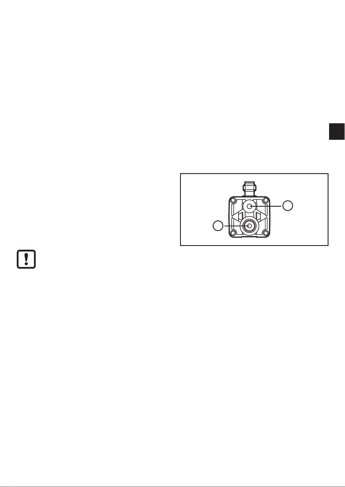
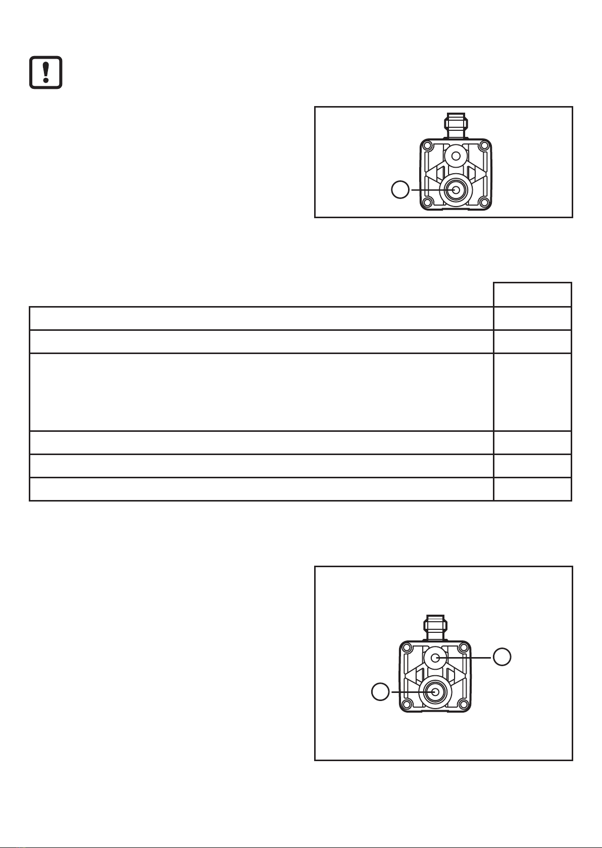
5�2 Pressure connections for differential pressure
measurement�������������������������������������������������������������������������������������������������8
5�3 DIN rail mounting�������������������������������������������������������������������������������������������9
5�4 Rear panel mounting �������������������������������������������������������������������������������������9
5�5 Mounting on a pressure-carrying rear panel������������������������������������������������10
5�6 Floor mounting��������������������������������������������������������������������������������������������� 11
5�7 Mounting on a maintenance unit �����������������������������������������������������������������12
6 Electrical connection������������������������������������������������������������������������������������������13
7 Operating and display elements ������������������������������������������������������������������������14
8 Menu������������������������������������������������������������������������������������������������������������������15
8�1 Menu structure���������������������������������������������������������������������������������������������15
8�2 Explanation of the menu������������������������������������������������������������������������������16
9 Parameter setting ����������������������������������������������������������������������������������������������17
9�1 General parameter setting���������������������������������������������������������������������������17
9�2 Setting of the output signals ������������������������������������������������������������������������19
9�2�1 Setting of the unit of measurement for system pressure ��������������������19
9�2�2 Setting of the output function��������������������������������������������������������������19
9�2�3 Setting of the switching limits �������������������������������������������������������������19
9�3 User settings (optional) �������������������������������������������������������������������������������19
9�3�1 Setting of a time delay for the switching signals���������������������������������19
9�3�2 Setting of the output logic for the switching outputs ���������������������������20

3
UK
1 Preliminary note
1.1 Symbols used
►Instruction
> Reaction, result
[…] Designation of keys, buttons or indications
→Cross-reference
Important note
Non-compliance may result in malfunction or interference
Information
Supplementary note
9�3�3 Setting of the damping for the switching outputs��������������������������������20
9�3�4 Configuration of the display ����������������������������������������������������������������20
9�3�5 Zero point calibration ��������������������������������������������������������������������������21
9�4 Service functions �����������������������������������������������������������������������������������������22
9�4�1 Reading of the min/max values for system pressure��������������������������22
9�4�2 Reset of all parameters to factory setting �������������������������������������������22
10 Operation���������������������������������������������������������������������������������������������������������22
10�1 Reading of the set parameters ������������������������������������������������������������������22
10�2 Fault indication ������������������������������������������������������������������������������������������22
10�3 Setting ranges �������������������������������������������������������������������������������������������23
11 Factory setting �������������������������������������������������������������������������������������������������24

4
2 Safety instructions
• The device described is a subcomponent for integration into a system�
- The manufacturer is responsible for the safety of the system�
- The system manufacturer undertakes to perform a risk assessment and to
create documentation in accordance with legal and normative requirements
to be provided to the operator and user of the system� This documentation
must contain all necessary information and safety instructions for the operator,
the user and, if applicable, for any service personnel authorised by the
manufacturer of the system�
• Read this document before setting up the product and keep it during the entire
service life�
• The product must be suitable for the corresponding applications and
environmental conditions without any restrictions�
• Only use the product for its intended purpose (→ Functions and features).
• Only use the product for permissible media (→ Technical data).
• If the operating instructions or the technical data are not adhered to, personal
injury and/or damage to property may occur�
• The manufacturer assumes no liability or warranty for any consequences
caused by tampering with the product or incorrect use by the operator�
• Installation, electrical connection, set-up, programming, configuration, operation
and maintenance of the product must be carried out by personnel qualified and
authorised for the respective activity�
• Protect units and cables against damage�

5
UK
3 Functions and features
The unit monitors the system pressure in pneumatic and compressed air networks
of machines and plants�
Applications
Compressed air (other media on request)
Type of pressure: relative pressure
Order no. Measuring range Permissible
overpressure Bursting pressure
bar PSI bar PSI bar PSI
PN7834 -1���10 -14�5���145 20 290 30 435
mbar PSI mbar PSI mbar PSI
PN7809
PY7809 -1 000���1 000 -14�5���14�5 20 000 290 30 000 435
MPa = bar ÷ 10 / kPa = bar × 100
Avoid static and dynamic overpressure exceeding the given overload
pressure by taking appropriate measures�
The indicated bursting pressure must not be exceeded�
Even if the bursting pressure is exceeded only for a short time, the unit
may be destroyed� NOTE: Risk of injury!
If pressures might occur which are higher than the permissible overpressure, you
should use other units of the PN70xx series� If you have any questions, please
contact ifm electronic's sales specialists�

6
4 Function
4.1 Processing of the measured signals
• The unit displays the current system pressure�
• It generates 2 output signals according to the parameter setting�
OUT1 • Switching signal for system pressure limit value�
OUT2
2 options
• Switching signal for system pressure limit value�
• Diagnostic signal (output 1 is inactive in case of a fault)�
4.2 Switching function
OUTx changes its switching state if it is above or below the set switching limits
(SPx, rPx)� The following switching functions can be selected:
• Hysteresis function / normally open: [OUx] = [Hno] (→ fig. 1).
• Hysteresis function / normally closed: [OUx] = [Hnc] (→ fig. 1).
First the set point (SPx) is set, then the reset point (rPx) with the requested
difference�
• Window function / normally open: [OUx] = [Fno] (→ fig. 2).
• Window function / normally closed: [OUx] = [Fnc] (→ fig. 2).
The width of the window can be set by means of the difference between SPx and
rPx� SPx = upper value, rPx = lower value�
1 2
P = system pressure; HY = hysteresis; FE = window

7
UK
4.3 Diagnostic function
Output 2 is used as diagnostic output based on the DESINA specification if
[OU2] = [dESI]�
• If there is no fault, the output is switched and carries UB+ (if P-n = PnP)
or UB- (if P-n = nPn)�
• In case of malfunctions in the following areas, the output is inactive:
- short circuit in output 1�
- EPROM function�
- RAM function�
- parameter setting�
- processor function�
4.4 Differential pressure measurement
Besides the main pressure connection
(1) the unit provides a ventilation
connection (2)� If both connections are
connected to the pressure system, the
unit can work as a differential pressure
sensor�
For proper function the following conditions must be met:
• The pressure at the main connection must always be greater than the
pressure at the ventilation connection�
• However, the pressure at the ventilation connection must not exceed
10 bar�
Note:
For differential pressure measurement the measurement accuracy deviates from
the specified accuracy (→ 12 Technical data). The deviation depends on the
amount of system pressure� It is 3�5 to 8�3 mbar per 1 bar system pressure�
The deviation can be minimised by setting an offset value (→ 9.3.5 Zero point
calibration)�

8
5 Mounting
Before installing and removing the unit: make sure that no pressure is
applied to the system�
►Screw the pressure connection or
adapter G⅛ to the main pressure
connection (1) and tighten�
Maximum tightening torque: 8 Nm�
Further possibilities: → the following sections.
5.1 Mounting accessories
The following components are available as accessories: Order no�
Mounting set for DIN rail mounting (DIN rail TH 35-7�5 to EN 60715) E37340
Adapter R⅛ to R⅛, can be aligned E37350
T pipe mounting set, includes:
• T pipe with 3 connections G½
• Reducer G½ to G⅛
• Adapter R⅛ to R⅛
E37360
Thread extension 1/8“ for flange mounting E30075
Push-in air fitting for tube Ø 6 mm E30076
Push-in air fitting for tube Ø 8 mm E30077
5.2 Pressure connections for differential pressure
measurement
►Remove the label from the
ventilation connection M5 (2),
connect to the pressure system�
Maximum tightening torque:
2�5 Nm�
►Connect the main pressure
connection G⅛ (1) to the pressure
system�
Maximum tightening torque: 8 Nm�

9
UK
5.3 DIN rail mounting
DIN rail TH 35-7�5 to EN 60715
►Fix the mounting clip (1) with the screws M4 x 40 (2) to the flange� Maximum
tightening torque: 2�5 Nm�
►Hook the unit into the DIN rail and clip it into place�
Removal:
►Lever out the mounting clip with a screwdriver at the top or at the bottom and
remove the unit�
5.4 Rear panel mounting
►Fix the unit with 2 screws M4 x 40 (1) (not included) to the rear panel�
Maximum tightening torque: 2�5 Nm�

10
5.5 Mounting on a pressure-carrying rear panel
1: main pressure connection
2: gland for pressure connection 2 mm
3: adapter plug (not included)
4: O-ring (not included)
5: fixing screws (not included)
► Cover the main pressure connection with an adapter plug G⅛ . Maximum
tightening torque: 8 Nm�
►Remove the gland for pressure connection�
►Insert the O-ring 3 x 2 and connect the connection to the medium-carrying
channel (diameter 2 mm)�
►Fix the unit with 2 screws M4 x 40 to the rear panel� Maximum tightening
torque: 2�5 Nm�

11
UK
5.6 Floor mounting
1: main pressure connection
2: fixing holes (4 threaded holes M3 or 4 bore holes with 4�5 mm diameter for fixing screws
M4)
3: bore hole for G⅛ adapter
4: bore hole for ventilation connection
5: fixing screws M3 (not included)
6: fixing screws M4 (not included)
►Arrange for bore holes for fixing screws and pressure connections in the floor
plate�
► Screw the pressure connection or adapter G⅛ to the main pressure
connection (1) and tighten� Maximum tightening torque: 8 Nm�
►For mounting in a pressure-carrying floor plate: insert an O-ring for sealing (not
included)�
►Place the unit on the floor plate� Screw 4 screws M3 from the top through the
flange into the floor plate� Maximum tightening torque: 1�5 Nm�
As an alternative:
►Place the unit on the floor plate� Screw 4 screws M4 from below through the
floor plate into the flange� Maximum tightening torque: 2�5 Nm�
The ventilation connection must not be obstructed by mounting or soiling�

12
5.7 Mounting on a maintenance unit
The unit can be integrated in maintenance units by means of an adapter R⅛
to R⅛ (order no. E37350) or by means of the T pipe mounting set (order no.
E37360)� When using the indicated accessories the pressure sensor can be
aligned�
Mounting with adapter
Mounting with T pipe mounting set

13
UK
6 Electrical connection
The unit must be connected by a qualified electrician�
The national and international regulations for the installation of electrical
equipment must be adhered to�
Voltage supply to EN 50178, SELV, PELV�
►Disconnect power�
►Connect the unit as follows:
2 x p-switching 2 x n-switching
Pin 1 Ub+
Pin 3 Ub-
Pin 4 (OUT1) • binary switching output pressure monitoring
Pin 2 (OUT2) • binary switching output if [OU2] = [Hno], [Hnc], [Fno] or [Fnc]
• diagnostic output if [OU2] = [dESI]
Core colours of ifm sockets:
1 = BN (brown), 2 = WH (white), 3 = BU (blue), 4 = BK (black)

14
7 Operating and display elements
1 to 8: Indicator LEDs
- LED 1 to LED 3 = system pressure in the unit of measurement which is indicated on the
label�
- LEDs 4 to 6: not used,
- LED 7, LED 8 = switching state of the corresponding output�
9: Alphanumeric display, 4 digits
- Indication of the current system pressure�
- Indication of the parameters and parameter values�
10: Set button
- Setting of the parameter values (scrolling by holding pressed; incrementally by pressing
once)�
11: Mode/Enter button
- Selection of the parameters and acknowledgement of the parameter values

15
UK
8 Menu
8.1 Menu structure

16
8.2 Explanation of the menu
SP1/rP1 Upper / lower limit value for system pressure at which OUT1 switches�
SP2/rP2 Upper / lower limit value for system pressure at which OUT2 switches�
OU1 Output function for OUT1:
• Switching signal for the pressure limit values: hysteresis function [H ��] or
window function [F ��], either normally open [� no] or normally closed [� nc]�
OU2 Output function for OUT2:
• Switching signal for the pressure limit values: hysteresis function [H ��] or
window function [F ��], either normally open [� no] or normally closed [� nc]�
• Diagnostic signal [OU2] = dESI�
EF Extended functions / opening of menu level 2�
Uni Standard unit of measurement for system pressure�
HI Maximum value memory for system pressure�
LO Minimum value memory for system pressure�
tCOF Teach zero-point calibration�
COF Manually enter the zero point calibration�
dS1/dS2 Switch-on delay for OUT1 / OUT2�
dr1/dr2 Switch-off delay for OUT1 / OUT2�
P-n Output logic: pnp / npn�
dAP Damping for the switching outputs�
diS Update rate and orientation of the display�
rES Restore factory settings�

17
UK
9 Parameter setting
During parameter setting the unit remains in the operating mode� It continues its
monitoring function with the existing parameters until the parameter setting has
been completed�
9.1 General parameter setting
3 steps must be taken for each parameter setting:
1Parameter selection
►Press [Mode/Enter] until the
requested parameter is displayed�
2Setting of the parameter value
►Press [Set] and keep it pressed�
> Current setting value of the
parameter flashes for 5 s�
> After 5 s: setting value is changed:
incrementally by pressing the button
once or continuously by keeping the
button pressed�
Numerical values are incremented continuously� To reduce the value: let the display
move to the maximum setting value� Then the cycle starts again at the minimum
setting value�
3Acknowledgement of the parameter
value
►Press [Mode/Enter] briefly�
> The parameter is displayed again�
The new setting value is stored�
Setting of other parameters:
►Start again with step 1�
Finishing the parameter setting:
►Press [Mode/Enter] several times until the current measured value is displayed or wait
for 15
s�
> The unit returns to the operating mode�

18
• Change from menu level 1 to menu level 2:
►Press [Mode/Enter] until [EF] is
displayed�
If the submenu is protected with an
access code,"Cod1" flashes in the
display�
►Press [Set] and keep it pressed until
the valid code no� is displayed�
►Press [Mode/Enter] briefly�
On delivery by ifm electronic: no access
restriction�
►Press [Set] briefly�
> The first parameter of the sub-menu
is displayed (here: [Uni])�
• Locking / unlocking
The unit can be locked electronically to prevent unintentional settings�
►Make sure that the unit is in the
normal operating mode�
►Press [Mode/Enter] + [Set] for 10 s�
> [Loc] is displayed�
During operation: [Loc] is briefly displayed if you try to change parameter values�
For unlocking:
►Press [Mode/Enter ] + [Set] for 10 s�
> [uLoc] is displayed�
On delivery: unlocked�
• Timeout:
If no button is pressed for 15 s during parameter setting, the unit returns to the
operating mode with unchanged values�

19
UK
9.2 Setting of the output signals
9.2.1 Setting of the unit of measurement for system pressure
►Select [Uni] and set the unit of measurement:
[bAr], [mbar], [MPa], [kPa], [PSI]�
9.2.2 Setting of the output function
►Select [OU1] and set the function:
- [Hno] = hysteresis function / normally open
- [Hnc] = hysteresis function / normally closed,
- [Fno] = window function / normally open,
- [Fnc] = window function / normally closed�
►Select [OU2] and set the function:
- [Hno] = hysteresis function / normally open,
- [Hnc] = hysteresis function / normally closed,
- [Fno] = window function / normally open,
- [Fnc] = window function / normally closed,
- [dESI] = output 2 is used as a diagnostic output�
9.2.3 Setting of the switching limits
►Select [SP1] / [SP2] and set the value at which the output switches�
►Select [rP1] / [rP2] and set the value at which the output switches off�
rPx is always smaller than SPx� The unit only accepts values which are
lower than the value for SPx�
9.3 User settings (optional)
9.3.1 Setting of a time delay for the switching signals
[dS1] / [dS2] = switch-on delay for OUT1 / OUT2�
[dr1] / [dr2] = switch-off delay for OUT1 / OUT2�
►Select [dS1], [dS2], [dr1] or [dr2] and set a value between 0�1 and 50 s
(at 0�0 the delay time is not active)�

20
9.3.2 Setting of the output logic for the switching outputs
►Select [P-n] and set [PnP] or [nPn]�
9.3.3 Setting of the damping for the switching outputs
►Select [dAP] and set a value�
dAP value = response time between pressure change and change of the
switching status in milliseconds�
The following fix values can be set; they define the switching frequency (f)
of the output:
dAP 3 6 10 17 30 60 125 250 500
f [Hz] 170 80 50 30 16 8 4 2 1
9.3.4 Configuration of the display
►Select [diS] and set the update rate and orientation of the display:
- [d1]: update of the measured values every 50 ms�
- [d2]: update of the measured values every 200 ms�
- [d3]: update of the measured values every 600 ms�
- [rd1], [rd2], [rd3]: display as for d1, d2, d3; rotated by 180°�
- [OFF]: the display is switched off in the operating mode�
This manual suits for next models
3
Table of contents
Other IFM Accessories manuals

IFM
IFM OGH User manual

IFM
IFM Efector500 PY7102 User manual

IFM
IFM Efector 410 Application guide

IFM
IFM PI16 Series User manual

IFM
IFM Efector 200 OJ User manual

IFM
IFM MFH User manual

IFM
IFM OID20 Series User manual

IFM
IFM Efector 100 GG712S User manual

IFM
IFM Efector 500 PI2652 User manual

IFM
IFM UIT509 User manual
Popular Accessories manuals by other brands

PASCO
PASCO PS-3219 reference guide

Naterial
Naterial ANEMO DC116 Assembly, Use, Maintenance Manual

Southern Enterprises
Southern Enterprises Holton Assembly instructions

Craftsman
Craftsman 358.792430 instruction manual

IFM Electronic
IFM Electronic efector 250 O2D22x operating instructions

PEMTECH
PEMTECH PT295 Series Operator's manual