DP1222 Converter 2 x 0...10 V / IO-Link
2
Contents
1 Preliminary note ............................................................. 3
1.1 Symbols used.......................................................... 3
1.2 Warnings used ......................................................... 3
2 Safety instructions............................................................ 4
3 Intended use................................................................ 5
4 Function ................................................................... 6
4.1 Operating modes ....................................................... 6
4.2 Application as an IO-Link device............................................ 6
4.2.1 General information.................................................. 6
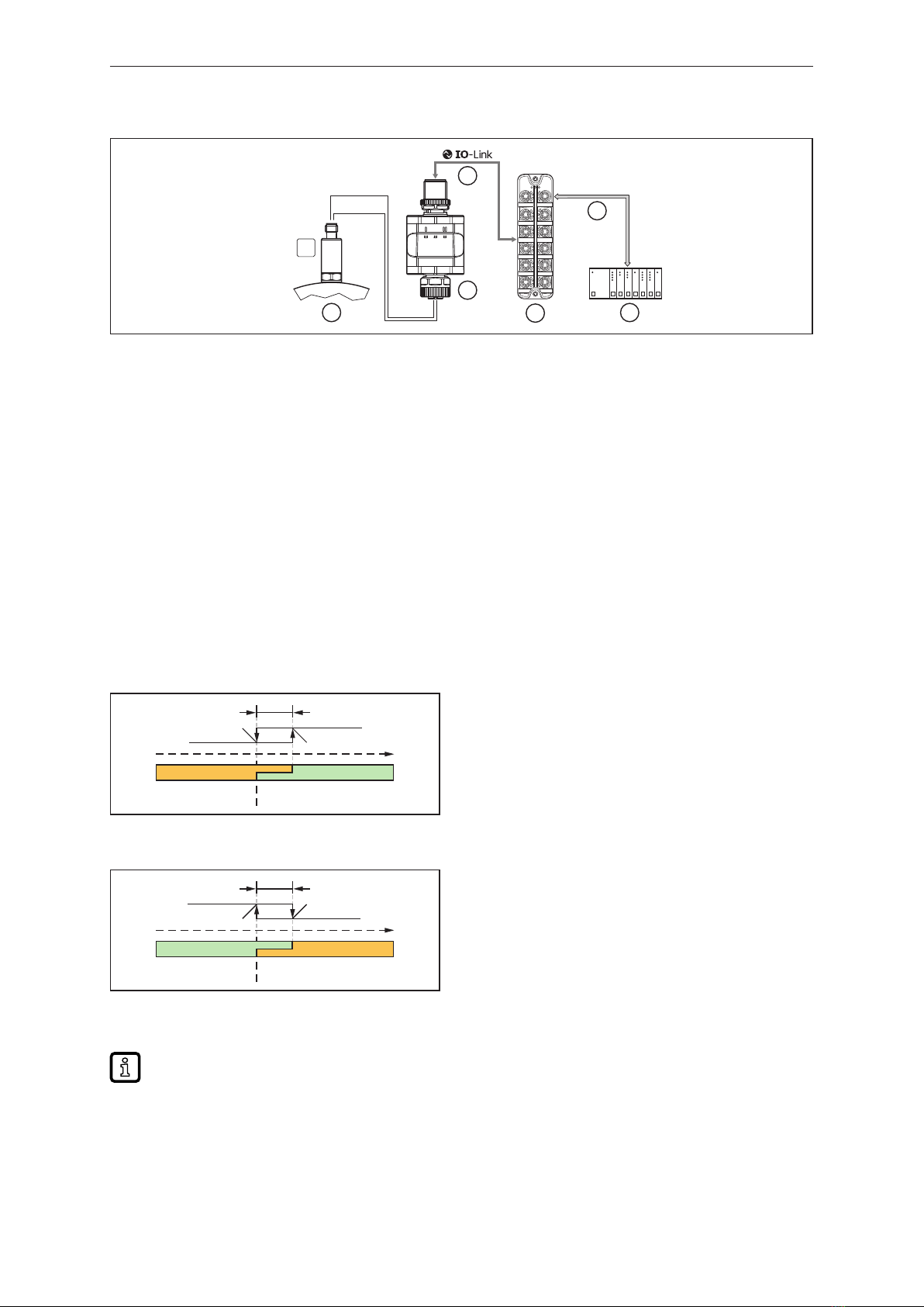
4.2.2 Application example ................................................. 7
4.2.3 IO Device Description (IODD).......................................... 7
4.3 Function diagrams....................................................... 7
4.3.1 Single point mode................................................... 7
4.3.2 Window mode...................................................... 8
4.3.3 Two point mode .................................................... 8
4.3.4 Deactivated mode................................................... 8
5 Installation.................................................................. 10
6 Electrical connection.......................................................... 11
6.1 Mounting the connector................................................... 12
6.2 Removing the connector.................................................. 12
6.3 Cable length........................................................... 12
7 Operating and display elements................................................. 13
7.1 LEDs................................................................. 13
7.1.1 Visualisation of the voltage value at the input . . . . . . . . . . . . . . . . . . . . . . . . . . . . . . 13
8 Parameter setting............................................................ 14
8.1 Parameters via IO-Link................................................... 14
8.1.1 Application-specific tag............................................... 14
8.1.2 Function Tag....................................................... 14
8.1.3 Location Tag....................................................... 14
8.1.4 internal_temperature – operating temperature microcontroller . . . . . . . . . . . . . . . . . 14
8.1.5 operation_hours – operating hours . . . . . . . . . . . . . . . . . . . . . . . . . . . . . . . . . . . . . . 14
8.1.6 ModE ─ switch point mode............................................ 14
8.1.7 LoGc ─ switch point logic ............................................. 14
8.1.8 SP1 ─ switch point 1................................................. 15
8.1.9 SP2 ─ switch point 2................................................. 15
8.1.10 HyS ─ switch points hysteresis......................................... 15
8.1.11 Mean filter......................................................... 15
9 Operation .................................................................. 16
10 Troubleshooting ............................................................. 17
11 Maintenance, repair and disposal................................................ 18
12 Factory settings.............................................................. 19