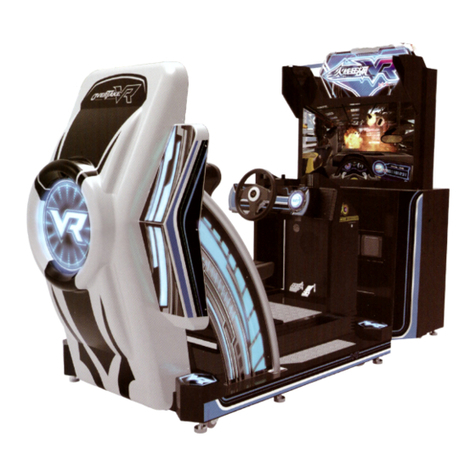
IGS WAHLAP TECH OverTake User manual

Please keep this manual properly for convenient reference as needed.
For safety reasons, please read the manual first before plugging in machine.
WARNING
OWNER
’
S MANUAL

About This Manual
Thank you for purchasing this product.
The manual describes how to install, set up, use and maintain the product.
The main purpose of the manual is to instruct how to operate the product
correctly and safely. Please follow all the safety and warning instructions in
the manual to avoid personal injury and product damage.
This product may only be maintained by a technician. A technician mainly
refers to a person who has obtained a certificate of senior middle school
related to mechanical engineering, electrical engineering or at a level equal
to that of technical senior middle school graduates, and is engaged routinely
in the maintenance, management, repair of amusement machine.
Please keep this manual properly for easy reference as needed. Moreover,
if the operator entrust another party to operate, move, transport, install,
maintain and repair the machine, please read relevant content and instruct
concerned party to observe all the instructions and precautions in this manual
regarding the particular action to be taken.
When transferring the ownership of this product, be sure to provide this
manual with the machine.
For further information about the game and repair (including consumables),
please contact our company.
©
©
GuangZhou Wahlap Technology Limited All Rights Reserved.
GuangZhou Wahlap Technology Limited All Rights Reserved.
Unauthorized reproduction of this document or any of its contents in
any form is strictly forbidden.

1. Safety Precautions ...............................................1
2. Product Introduction ..............................................6
3. Game Description ...............................................16
4. Test and Setting .................................................19
1.1 Warning Stickers .........................................................1
2.1 Product Specification ......................................................6
3.1 Appearance Design.......................................................16
3.3 How to Play.............................................................16
3.4 Connection and turning on the power .......................................17
3.5 Setting the group number and player ID......................................18
3.2 Game Introduction .......................................................16
4.2.1 Using the operator settings............................................24
4.3.1 Connection status ...................................................25
4.3.2 I/O test ............................................................26
4.3.3 Force feedback test .................................................27
4.3.4 Lamp test .........................................................28
4.3.5 Screen test.........................................................29
4.3.6 Speaker test .......................................................30
4.3.7 Vibration seat test ...................................................30
4.3.8 Keypad test ........................................................31
4.3.9 Counter test ........................................................31
4.4.1 I / O adjustment.....................................................33
4.1.1 Game control ......................................................20
4.1.2 Game control ......................................................21
4.1 Distinctive plays .........................................................19
4.2 Framework of the menu ..................................................23
4.4 Game settings ...........................................................32
4.3 Hardware test............................................................25
2.2 Overview ...............................................................7
2.3 Spare Parts..............................................................8
2.4 Shipment List ............................................................9
2.5 Packing List ............................................................11
2.6 Install Direction .........................................................12
2.7 Warranty ..............................................................15
1.2 Placing Site .............................................................1
1.3 Safety Precautions ........................................................2
1.4 Precaution during Play.....................................................3
1.5 Transporting and Moving ..................................................3
1.6 Installing and Placing .....................................................4
1.7 Caution & Warning Stickers ................................................5
Table of Contents
About This Manual

4.4.2 Country ...........................................................33
4.4.3 Store .............................................................34
4.4.4 Difficult setting .....................................................34
4.4.5 Tunnel setting .....................................................35
4.4.6 Coin settings ......................................................35
5. Maintenance and Service .........................................48
5.1 Maintenance and Service ................................................48
5.2 Replacing parts ........................................................49
5.2.1 Replacing fl uorescent tube ...........................................49
5.2.2 Replacing the keypad / View button.....................................49
5.2.3 Replacing the boost button and the light plate ............................50
5.2.4 Replacing the side light plate ..........................................50
5.2.6 Replacing the brake light plate ........................................51
5.2.5 Replacing the exhaust light plate ......................................51
5.2.7 Replacing the vibration speaker under the seat ...........................52
5.2.8 Replacing the vibration speaker behind the seat ..........................52
5.2.9 Replacing the speaker behind the seat ..................................53
5.2.10 Replacing the bottom seat back light ..................................53
5.2.11 Replacing the dashboard LED light plate ...............................54
5.2.12 Replacing front speaker .............................................54
5.2.13 Replacing the pedals of the throttle and brake ..........................55
5.2.14 Replacing the VR of the steering wheel ................................55
5.2.15 Replacing the VR of the pedals of the throttle and brake...................56
5.2.16 Replacing the bass speaker .........................................56
5.2.17 Maintaining the E3100 ..............................................57
5.2.18 Maintaining the full-range AMP .......................................57
5.2.19 Replacing the power supply and isolation transformer.....................58
5.2.20 Replacing I / O board / motor control board .............................58
4.4.7 Multiplayer setting .................................................36
4.4.8 Volume setting ....................................................37
4.4.9 Flow time setting ...................................................38
4.4.10 Ranking board reset ...............................................38
4.5.1 Connection setting ..................................................39
4.6.1 Daily income .......................................................43
4.6.2 Monthly income ....................................................44
4.6.3 Total income .......................................................45
4.6.4 Income data reset...................................................46
4.5.2 Time setting .......................................................40
4.5.3 System reset ......................................................40
4.5.4 Player data setting ..................................................41
4.5 System settings .........................................................39
4.7 Troubleshooting ..........................................................47
4.6 Income data ............................................................42

6. Assembly .......................................................59
7. Printing Pattern ..................................................99
8. Wiring Diagram .................................................101
9. After-Sales Service..............................................104
6.1 Assembly tree diagram ....................................................59
6.2 Final host-machine assembly ...............................................60
6.3 Host-machine assembly....................................................61
6.4 Base assembly ..........................................................80
6.5 Light box assembly........................................................87
6.6 Display assembly .........................................................92
6.7 Seat assembly ..........................................................93
6.8 Display supportingg frame..................................................98
6.3.1 Host-machine frame assembly .........................................63
6.3.2 Host machine assembly ..............................................64
6.3.3 Power pack assembly ................................................65
6.3.4 Power amplifier assembly .............................................66
6.3.5 I/O board assembly .................................................67
6.3.6 Coining frame assembly .............................................68
6.3.7 AC assembly-box ...................................................69
6.3.8 Back service-door assembly ..........................................70
6.3.9 Steering-wheel and lamp-plate assembly ................................71
6.3.10 Control panel assembly (Chinese version - card reader) ...................72
6.3.11 Control panel assembly (English version - digital buttons) .................73
6.3.12 Pedal assembly ....................................................74
6.3.13 High-pitched sound box assembly .....................................75
6.3.14 Motor assembly ....................................................76
6.3.15 Bass loudspeaker assembly .........................................77
6.3.16 Transformer assembly ..............................................78
6.3.17 Steering-wheel assembly.............................................79
6.4.1 Base-frame assembly ................................................81
6.4.2 Lamp base-plate assembly ............................................82
6.4.3 Ransformer base-plate assembly .......................................83
6.4.4 Left-side exhaust-pipe assembly........................................84
6.4.5 Right-side exhaust-pipe assembly ......................................85
6.4.6 Fan assembly .......................................................86
6.5.1 Light-box frame assembly .............................................88
6.5.2 Light-box left-side assembly ...........................................89
6.5.3 Light-box right-side assembly ..........................................90
6.5.4 Card-board assembly ................................................91
6.7.1 Seat frame assembly .................................................94
6.7.2 Seat-cover assembly .................................................95
6.7.3 Seat-base assembly..................................................96

1.1 Warning Stickers
1.2 Placing Site
In order to avoid injury to related people and damage to property, please
observe the followings:
PLEASE READ FIRST
PLEASE READ FIRST
The following marks can be used to indicate the magnitudes of risk and
damage caused by ignorance or improper operation:
Warning
Warning
Warning
Warning
Caution
Caution
means “may result in serious injury or death”
means “may result in minor injury or property
damage”
Serious Injury
Serious Injury
: refers to the situations in which hospital treatment or long-term treatment
will be accepted because of losing sight, getting hurt, getting burnt, electric
shock, fracture or intoxication.
Minor Injury
Minor Injury
: refers to the cases that there is no need to go to hospital or accept long-term
treatment.
Property Damage
Property Damage
: refers to the damage of house, facility, or hurt of livestock and pet
This machine is designed for indoor use only. Never install the machine
outdoors. Meanwhile, please avoid the following locations indoor:
The rear part has the vent for heat emission from PC or screen.
Don’t place anything nearby to avoid game failure.
Provide a space of minimum 30cm between the rear of the machine
and the wall for good ventilation and heat emission
1. Safety Precautions
Direct sunlight, water leakage, damp and high temperature places.
Near Flammable, volatile, or/and dangerous substance.
Slope, unstable places or locations subject to frequent vibration.
Near emergency exit, fire extinguisher or similar equipment.

Warning
Warning
1.3 Safety Precautions
The owner shall pay attention to the followings when placing, checking
and repairing machine to insure player’s security and avoid damage:
Make sure to plug the game into 110V or 220V main outlet to avoid fire
and electric shock.
Do not unplug or plug the plug instantly.
Don’t touch the power plug with a wet hand to avoid electric shock.
Don’t expose the power cord/grounding line on the passageway.
Failure to do this will damage the power cord, causing electric shock
or short circuit.
Don’t lay anything near the power cord to avoid fire.
Do not pull the power cord when unplugging, please hold the plug to
avoid power cord damage, causing fire or electric shock.
Only use fuse and spare parts specified by our company
Connect the connector firmly and tighten the screws.
Do not dismount, replace or convert the product without our permission
in order to avoid damage and human injury due to improper operation.
Check and maintain the machine regularly.
Keep “Warning stickers” clean and legible. Replace it immediately
when the words are not legible or the dirt can’t be removed.
Please contact our service center when performing any work that is
not described in this manual, and follow the instruction provided.
Make sure to turn off the power when performing maintenance and
service to avoid electric shock or short circuit.
In case of power cord damage, please contact the local distributor for
replacement

Transporting
Transporting
When transporting the machine with an elevator, be sure to employ “Lift Point”
to prevent accident and damage to the machine.
To prevent movement when transporting the machine on a vehicle, please fix the
casters and fully retract the adjusters. Failure to do this may cause damage to the
machine.
When carrying the machine with a forklift, be sure to insert the fork to fork position
and lift stably. If not, it may cause accident and damage to the machine.
The glass and LCD screen are fragile. Avoid violent vibration or shock when
transporting.
Moving
Moving
Before moving the machine, unplug the power plug to prevent accident.
Don’t damage the cord.
Pay attention to the obstructions and uneven surface when moving the machine
to prevent accident and damage to the machine.
Fully retract all adjusters before moving to prevent accident and hazard.
Make sure to use at least two persons to conduct the above work to avoid accident
and injury
Pay attention to the moving direction, see fig.
1.4 Precautions during Play
Caution
Caution
Caution
Caution
Person with poor health condition, such as hypertension or heart disease.
When a player feels uncomfortable during play, remind the person to have
a break, or stop playing.
Make sure the player reads the warning labels and other indications, and
plays in accordance with the instructions to avoid accidents such as electric
shock and short circuit.
Bystander shall not operate any button when the player is playing the game
to avoid unnecessary trouble.
In order to avoid injury and accident during play, the following people shall
not play the game:
People who are injured or less mobile.
Person wearing high-heeled or slippery shoes.
Person who can’t touch the pedal.
Pregnant woman, drunk people.
1.5 Transporting and Moving

Use the adjusters to fix the machine (See diagram 1)
1.Loosen the nuts for the adjusters (clockwise), tighten the bolts with a wrench (clockwise).
2.Tighten the nut firmly(counter clockwise) and fix it well.
Diagram (1)
Diagram (2)
Provide a space of minimum 30cm between the rear of the machine and
the wall for good ventilation and heat emission (See diagram 2).
Wall
bracket
Lock nut
Lock place
Caster Adjuster Bolt
Caution
Caution
1.6 Installing and Placing
Pay attention to the following when placing the machine.
Place the machine on the flat and slip resistant area.

1.7 Caution & Warning Stickers

6
6
1108(W)×1693(D)×2335(H)
1108mm
2335mm
1693mm
2. Product Description
2.1 Product Specification
Indoor Only
220V
50Hz
750W
280kg
Location
Dimension
Rated Voltage
Frequency
Power Consumption
Weight
Temperature Range 5~40 。
C
Front View Side View

7
7
2.2 Overview
Rear View
Bottom View
Side View
Top View

8
8
2.3 Spare Parts
Host machine
Host- machine base
Seat
4X exhaust pipes
Steering wheel
Display
Coining door
Shifting fork
Accelerator and the brake
Billboard acrylic
Card-board components
Right side of light box
Light box
Back service-door
AC box
Light box
Display supporting frame

9
9
2.4 Shipment List
Packing Carton 1
7
1
6
1
2
1
1
1
3
1
5
1
4
1
7 HXK-9901E05
座椅天盖
耐水3C 1100g T-10 1
6 HXK-9901E04
座椅围框
耐水3C 1100g T-10 1
5 HXK-9901E03
座椅地台架限位木条二
实木40*20*767 1
4 HXK-9901E02
座椅地台架限位木条一
实木40*20*500 1
3 HXK-9901E01
座椅地台架
1
2 HXK-9903000
灯箱左右侧及豪卡板包装
1
1 HXK-0200000A 座椅组件 1
序号 图 号 名 称 材料/规格 数量
备注

10
10
Packing Carton 2
6
1
5
1
2
1
7
1
1
1
4
1
3
1
7附属品纸箱 345*255*110mm 1
6 HXK-9902E05 机台主体天盖 耐水3C 1100g T-10 1
5 HXK-9902E04 机台主体围框 耐水3C 1100g T-10 1
4 HXK-9902E03 机台主体地台架限位木条二实木40*20*700 1
3 HXK-9902E02 机台主体地台架限位木条一实木40*20*1020 1
2 HXK-0100000A 机台主体组件 1
1 HXK-9902E01 机台主体地台架 1
序号 图 号 名 称 材料/规格 数量 备注

11
11
Same-size key 5555 keys 2
Power line (3 pins at both ends ) 3m(1.0m㎡)1
Flat gasket
Flat gasket
φ6*φ20*2.0(chrome-plated)6
φ5*φ12*1.0(black-plated)10
Large hexagon socket flat head screw M5*12 (chrome-plated) 20
Large cross-head flat screw M4*12((black-plated)) 22
Hexagonal screw M8*50(black-plated)4
Flat gasket φ8*φ22*2.0(black-plated)4
Spring washer M8(black-plated)4
Hexagonal screw M6*25(black-plated)12
Flat gasket φ6*φ20*2.0(black-plated)12
Spring washer M6(black-plated) 12
Operating instructions Coated paper 1
Lateral junction plate of host
machine SPCC-3.0T 2
Network cable gigabit network cable 10M 1
2.5 Packing List
Please check the following items after purchasing our product. If any part
missing or damaged, please contact our sales person!
Description Specification Quantity Remarks

12
12
Step 1
Step 2
2.6 Install Direction
Reinforced plastic sheet metal of exhaust-pipe
Right-side plastic of exhaust pipe
Right-side assembly of exhaust pipe
1. First of all, the two pieces of reinforced-plastic sheet metals of exhaust-pipe are fixed to the base
with the large cross-head flat screws (black-plated).
2. After the right-side assembly of the exhaust pipe is fixed to the base with 3 large cross-head flat
screws M4 * 12 (black-plated), then the wires on the exhaust pipe are connected properly.
3. The right-side plastic of the exhaust pipe is fixed to the base with 5 flat-head screws M4 x 25
(black-plated).
1. After the display assembly is taken out of the packaging box, the display service panel and the
display cover-plate are removed respectively, then the display is removed to have the display
separated from the display supporting frame.
2. First of all, use the hexagonal screws M8 * 50 (black-plated), spring washers M8 (black-plated)
and flat gaskets φ8*φ22*2.0 (black-plated) to install the display supporting frame to the host machine;
Reuse the screws removed from the display to install the display to the display supporting frame.
3. After 4 screws on the back service-door are removed, use the same-size key to open the door in
order to have the connecting wires connected properly.
Display
Display supporting
frame
Display deck-plate
Display back service-door
Host machine
Display service-panel

13
13
Step 3
Step 4
Light-box framework
1. First of all, hang the light-box framework onto the supporting frame and connect the wires on the
light-box framework properly, then use 8 cross-head round screws M5 * 16 (black-plated) to fix
the light-box framework to the display supporting frame.
2. Reinstalled the display deck-plate, display service-panel and back service door to its places.
Light box
Display
Left side of the light box
Right side of the light box
Card board components
1.When both sides of light box are installed, plug in the connectors at the left and right sides of light
box and put the connectors into the light box , and then use M5 * 12 (chrome-plated) to fix the
both sides to the light box.
2.After the left and right sides of the light box are fixed properly, put the card-board components
onto the host-machine and align the screw-holes, and then use M5 * 12 (chrome-plated)
hexagonal-socket flat head screws and flat gasketsφ6*φ20*2.0 to tighten.

14
14
Step 5
Right side of the light box
Card board components
Billboard acrylic
Billboard acrylic
decorative sheets
3. Put the long holes on either side of billboard acrylic onto the studs on either side of the light box,
and then use M5 * 12 (chrome-plated) hexagonal-socket flat head screws to fix billboard acrylic
decorative sheets onto billboard acrylic.
2.Remove 4 M4*25 (black-plated) hexagonal-socket flat head screws, unlock the seat, then put
the seat up, use the hexagonal flat head screws M8 * 50 (black-plated), flat gasket Φ8*φ22*2.0
(black-plated) and spring washer M8 (black-plated to connect the host-machine with the seat,
lock the seat and retighten the 4 removed hexagonal flat head screws.
1.First of all, connect the connecting wires between the host machines and seat properly and the
host-machine shall be near to the seat.
3.Use hex screws M6 * 25 (black-plated), flat gaskets φ6*φ20*2.0 (black-plated) and spring washers
M6 (black-plated) to tighten the two pieces of junction plates at the outboard of the host machine.

15
15
Damage caused by force majeure such as god will.
Failure caused by carelessness, such as water contact, falling down,
toppling, knocking.
Failure caused by disobeying the instructions in this manual.
Failure caused by operating the machine on inappropriate site.
Change the original design and configuration for the game without notice.
Failure to perform regular service and clean.
Failure to fix the product in line with the manual’s requirement.
Malfunction or part damage caused by electromagnetic interference other
electronic equipments generated.
Non-warranty Consumables
Light tube and bulb
Button lamp and switch
Fragile items
Solenoid
Other spare parts
2.7 Warranty
Scope
Inquiry regarding product can be assisted for free.
The warranty scope for consumables and durables may differ from product
to product. Please contact our after-sales service center for detailed
information. The right of final interpretation is reserved.
Exclusive
Table of contents
Other IGS Arcade Game Machine manuals
Popular Arcade Game Machine manuals by other brands
UNIS
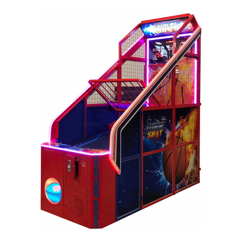
UNIS Extreme Shot Operation manual
Home Leisure Direct
Home Leisure Direct ARCADEPRO Nebula user manual

Barron Games
Barron Games X-Putt Operator's guide

Gameart
Gameart Hurricane user manual

BMI Gaming
BMI Gaming FOOL THE GUESSER operating instructions

Adrenaline Amusements
Adrenaline Amusements Blackout Prize BO-46-1001 Operation & service manual
Coastal Amusements
Coastal Amusements TOY SOLDIER operating manual

Home Leisure Direct
Home Leisure Direct ARCADEPRO ULTRA user manual
Nitto
Nitto Fantasy Forest Bowling user manual
Tecway
Tecway Max Roller manual
Andamiro
Andamiro KING OF THE HAMMER user manual
Coastal Amusements
Coastal Amusements Plinko operating manual
