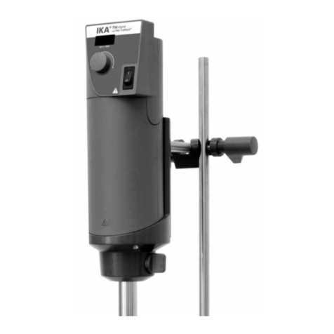
IKA ULTRA-TURRAX T50 basic User manual

12
Safety instructions
ō0DNHFHUWDLQWKDWWKHXQLWLVVHWDWWKHORZHVW
speed before commissioning; otherwise, the
unit will begin running at the speed last set.
Gradually increase the speed.
ō5HGXFHWKHVSHHGLIWKHPHGLXPVSODVKHVRXWRI
the vessel because the speed is too high.
ō%HIRUHVZLWFKLQJRQWKHGLVSHUVLQJLQVWUXPHQW
make sure that its shaft is immersed min. 100
mm in the medium to prevent the medium
from splashing out.
ō7KHGLVWDQFHEHWZHHQWKHGLVSHUVLRQWRRODQG
the vessel bottom should not be less than 50
mm (fig. 1).
ō(QVXUHWKDWWKHVWDQGGRHVQRWVWDUWWRPRYH
ō
In the event of unbalance or unusual noises,
switch off the appliance immediately. Replace
the dispersing element. If there is no difference
after the change of the dispersing tool, return it
to the dealer or the manufacturer along with a
description of the fault.
ō'RQRWWRXFKURWDWLQJSDUWVGXULQJRSHUDWLRQ
ō Caution: Burns hazard! When in operation,
the dispersing element and the coupling flange
can become hot.
ō'RQRWFRYHUWKHYHQWLODWLRQVORWVRQWKHGULYHLQ
order to ensure adequate cooling of the drive.
ō'RQRWSURFHVVDQ\ĠDPPDEOHRUFRPEXVWLEOH
materials.
ō 3URFHVV SDWKRJHQLF PDWHULDOV RQO\ LQ FORVHG
vessels under a suitable extractor hood. Please
contact IKA®if you have any questions.
ō'RQRW RSHUDWHWKHDSSOLDQFHLQH[SORVLYH DW
mospheres, with hazardous substances or un-
der water.
ō7KHUHPD\EHHOHFWURVWDWLFGLVFKDUJHVEHWZHHQ
the medium and the dispersing instrument
shaft which could pose a direct danger.
ō2QO\SURFHVVPHGLDWKDWZLOOQRWUHDFWGDQJH
rously to the extra energy produced through
processing. This also applies to any extra ener-
gy produced in other ways, e.g. through light
irradiation.
ō0HWHUSRZGHUQRWWRRFORVHWRWKHĠDQJH3RZ
der can be blown away by air turbulences of
the drive.
ō
Safe operation is only guaranteed with the ac-
cessories described in the ”Accessories” chapter.
ō $OZD\V GLVFRQQHFW WKH SOXJ EHIRUH ğWWLQJ DF
cessories.
ō7KHDSSOLDQFHFDQRQO\EHGLVFRQQHFWHGIURP
the mains supply by pulling out the mains plug
or the connector plug.
For your protection
ōRead the operating instructions in full be-
fore starting up and follow the safety ins-
tructions.
ō.HHSWKHRSHUDWLQJLQVWUXFWLRQVLQDSODFHZKH
re they can be accessed by everyone.
ō(QVXUHWKDWRQO\WUDLQHGVWDIIZRUNZLWKWKHDS
pliance.
ō)ROORZWKHVDIHW\LQVWUXFWLRQVJXLGHOLQHVRFFX
pational health and safety and accident preven-
tion regulations.
ō :HDU \RXU SHUVRQDO SURWHFWLYH HTXLSPHQW LQ
accordance with the hazard category of the
media to be processed. Otherwise there is a
risk from:
- splashing and evaporation of liquids
- body parts, hair, clothing and jewellery get-
ting caught.
ō6HWXSWKHVWDQGLQDVSDFLRXVDUHDRQDQHYHQ
stable, clean, non-slip, dry and fireproof sur-
face.
ō &KHFN WKH DSSOLDQFH DQG DFFHVVRULHV EHIRUH
hand for damage each time you use them. Do
not use damaged components.
ō7KHDSSOLDQFHLVQRWVXLWDEOHIRUPDQXDORSH
ration.
ō7KHDJLWDWLRQYHVVHOVXVHGIRUGLVSHUVLQJKDYH
to be secured. Consider on a good stability of
the entire structure.
ō6HFXUHWKHDJLWDWLRQYHVVHODJDLQVWWZLVWLQJ
ō &KHFN WKDW WKH WXUQLQJ NQREV DUH VHFXUH DQG
tighten if necessary.
ō *ODVV YHVVHOV PXVW DOZD\V EH VHFXUHG ZLWK D
clamp to prevent them spinning. When wor-
king with flasks elastic couplers must be used
to prevent fracture of the glass.
ō1RWHWKHRSHUDWLQJLQVWUXFWLRQVRI WKHGLVSHU
sing tool and accessories.
ō 2QO\ GLVSHUVLQJ HOHPHQWV DSSURYHG E\ IKA®
may be used.
ō3OHDVHREVHUYHWKHSHUPLWWHGVSHHGIRUWKHGLV
persing element. Never set higher speeds.
ō'RQRWXVHWKHDSSOLDQFHZLWKRXWDGLVSHUVLQJ
element.
ō8VHWKHGLVSHUVLQJWRRODOZD\VLQVLGHWKHVWLUULQJ
vessel.
ō 1HYHU UXQ GLVSHUVLRQ WRROV GU\ DV WKH JDVNHW
and bearings will be destroyed if the tools are
not cooled by the medium.
ōCaution: Burns hazard! If a dispersing element
is not inserted into the drive flange as far as the
mark it can become extremely hot in operation
and thus suffer damage.
DANGER!

13
Unpacking
ōUnpacking
- Please unpack the device carefully
- In the case of any damage a fact report must
be sent immediately (post, rail or forwarder)
ōDelivery scope
IKA ULTRATURRAX®T 50 digital
- Disperser T 50 digital
- Extension arm
- Hexagon socket screw
- Shaft key
- Generator key
- Screwdriver DIN 911
- Operating instruction
ōApplication
When used in combination with one of our re-
commended dispersing elements, the drive unit
is a high-speed dispersing and emulsifying unit
capable of handling free-flowing and liquid
media in batches.
- Production of:
Emulsions
Dispersions
Wet crushing
- Operating modes:
on stand
Correct use
ōRange of use
- Laboratories - Schools
- Pharmacies - Universities
The safety of the user cannot be guaranteed if
the appliance is operated with accessories that
are not supplied or recommended by the manu-
facturer or if the appliance is operated improper-
ly contrary to the manufacturer’s specifications
or if the appliance or the printed circuit board
are modified by third parties.
ō7KH VRFNHW IRU WKHPDLQV FRUGPXVW EH HDVLO\
accessible.
ō7KHDSSOLDQFHGRHVQRWVWDUWXSDJDLQDXWRPD
tically following a cut in the power supply.
For protection of the equipment
ō7KHDSSOLDQFHPD\RQO\EHRSHQHGE\H[SHUWV
ō7KHYROWDJHVWDWHGRQWKHW\SHSODWHPXVWFRU
respond to the mains voltage.
ō5HPRYDEOHSDUWVPXVWEHUHILWWHGWRWKHDSSOL
ō $EUDVLRQ RI WKH GLVSHUVLRQ HTXLSPHQW RU WKH
rotating accessories can get into the medium
you are working on.
ance to prevent the infiltration of foreign ob-
jects, liquids etc..
ō 3URWHFW WKH DSSOLDQFH DQG DFFHVVRULHV IURP
bumps and impacts.

14
Drive
Useful information
The speed is set by using the differently adjusting
wheel. The motor speed can be read off the LED
display. For example, a value of 8.6 corresponds
to 8,600 rpm.
The drive unit opens up a wide range of possibili-
ties for dispersion technology in the conventional
laboratory with a respective performance output
of approximately 700 watts at 10,000 rpm.
The dispersion effectiveness is heavily dependent
on the product of the shear gradient and the time
the particles spend in the shear zone. The opti-
mum range for the circumferential velocity of the
rotor/stator arrangement is 10-24 m/s.
A processing time of a few minutes is usually
su cient to produce the desired fineness. Long
processing times bring only insignificant impro-
vements in the obtainable fineness; the energy
expended serves merely to increase the tempera-
ture of the medium.
Dispersion is the dissolution and diffusion of a so-
lid, liquid or gaseous phase in a liquid that is not
consolute with that phase.
The rotor/stator principle
Due to the high rotation speed of the rotor, the
medium to be processed is automatically drawn
axially into the dispersion head and then forced
radially through the slots in the rotor/stator arran-
gement. The high accelerations acting on the ma-
terial produce extremely strong shear and thrust
forces. In addition, high turbulence occurs in the
shear gap between rotor and stator, which provi-
des optimum mixing of the suspension.
RO
TO
R
ST
AT
OR
Assembly of boom and stand
For safety the drive unit should be fastened to the
telescopic stand R 2723 (5) or the stand R 2722
(5) using the cross sleeve R 271 (3).
In order to enhance the stability of the mecha-
nical arrangement, the driving unit has to be
mounted as close as possible to the stand pillar
The delivered extension arm is mounted as fol-
lows (overview fig. 1):
ō,QVHUWH[WHQVLRQDUPSRVLQWRĠDQJH
ō6FUHZLQWKHFKHHVHKHDGVFUHZSRV
ō)LUPO\WLJKWHQFKHHVHKHDGVFUHZSRV
using the DIN 911 A/f 4 screwdriver
Vibrations may cause the cylinder head screw
(pos. 2) to loosen. Therefore, for your own sa-
fety, periodically check that the extension arm is
secure. If necessary, retighten the cylinder head
screw (pos. 2).
Fig. 4

15
Working with the unit
Refer to the operating instructions for the filling
level of the medium and the immersion depth
into the dispersing element used.
Caution: Burns hazard! If a dispersing element
is not inserted into the drive flange as far as the
mark it can become extremely hot in operation
and thus suffer damage.
So as to avoid unintentional ingress of air into the
medium due to excessively turbulent rotation, the
whole unit can be placed a little off centre in the
stirring vessel.
By using the turning knob (pos. 10) the speed may
be infinitely varied to meet the requirements of the
medium to be processed.
The idle speed for the drive unit can be adjusted
in the range 600 and 10 000 rpm; the value will
be shown on the LED display.
If these conditions are met
the unit is ready for service
when the mains plug has
been plugged in.
The driving unit is switched on by means of the
On/Off- switch (pos. 9).
Also pay attention to the ambient conditions lis-
ted in the “Technical data”.
Assembling the dispersion tool
(Overview fig. 5)
- Open the knurled screw (pos. 3) so that the th-
read does not protrude into the hole.
- Insert the dispersing element (pos. 2) from
the bottom into the drive unit (pos. 1) as far
as the stop.
The shaft will audibly click into
place when a small amount of force is ap-
plied (sprung ball bearing) - depending on
the type of disperser. The dispersing element
is fitted correctly if the dispersing element is
flush with the bottom edge of the drive unit.
- Attention: Now secure the dispersing element
by screwing the knurled screw tight (pos. 3).
Maintenance and cleaning
Fig. 5
0 mm
!
!
1
3
2
2
Spare parts order
When ordering spare parts, please give:
- Machine type
- Manufacturing number, see type plate
- Item and designation of the spare part,
see www.ika.com, spare parts diagram and
spare parts list
Repair
In case of repair the device has to be cleaned and
free from any materials which may constitute a
health hazard.
For this use the "certificate of compliance" or
download the form from the IKA®website
www.ika.com.
If you require servicing, return the appliance in its
original packaging.
Storage packaging is not sucient. Please also
use suitable transport packaging.
The drive unit is maintenance-free but not immu-
ne from wear. The motor brushes and the coup-
ling wear out over time.
Cleaning
For cleaning disconnect the
main plug.
To clean the drive use only water with a detergent
that contains tensides, or use isopropylalcohol for
stubborn soiling (not for plastic parts).
Dispersion tools: Consider please the manuals
associated to the dispersion tools.
- Do not allow moisture to get into the appliance
when cleaning.
- Wear protective gloves when cleaning the de-
vices.
- Please consult with IKA®before using any
cleaning or decontamination methods, other
than those recommended here.

16
Accessories
ō5&URVVVOHHYH
ō5+ 7HQVLRQHU
ō56WDQG
ō57HOHVFRSLFVWDQG
ō5&URVVVOHHYH
Permitted dispersion tools
Dispersing tools serie S 50...
Abbreviations:
S 50 : consistent with dispersing unit T 50
N : PTFE bearing
R 50 high speed : Agitator shaft
G 45 G, G 45 M, G 45 F, W 65 SK / W 80 SMK :
Stator/shaft tube diameter
G : Thick; M: Medium; F : Fine
Speed range : upto 10,000 rpm
Designation Shaft material
S50N-G 45 G Stainless steel
S50N-G 45 M Stainless steel
S50N-G 45 F Stainless steel
S50N-W 65 SK Stainless steel
S50N-W 80 SMK Stainless steel
R 50 high speed Stainless steel
Accessories:
ō5'LVVROYHUGLVF 6WDLQOHVVVWHHO
ō53URSHOOHU 6WDLQOHVVVWHHO
For applications and further information, please
see the operating instructions of the dispersing
element.
Only use the dispersion tools listed in the
table and note the according operating in-
structions of the dispersion tool.

17
Error codes
Proceed as follows in case of error:
- Switch off device using the main switch
- Carry out corrective measures
- Restart the device
Error Cause Effect Solution
code
Er.3 Overtemperature
Device will switch automatically Motor speed - Allow device to cool down
to cooling mode if operated with set autom- - Allow to continue running in cooling mode
excess load atically
(not adjust-
- Switch device off. Switch on again after some time.
able)
(Duration depends on the magnitude of the over-
tempertature)
Er.4 Speed variation
Speed variation due to blockage, Device off - Switch off device
faulty electronics, overload, motor - Eliminate cause of overload or blockage
brushes worn (remove dispersing element)
- Replace motor brushes
- Switch on device
- If the actions described fail to resolve the fault,
contact the IKA®service department,
Send the device for repair, including a short
description of the fault.
Er.6* Undervoltage
Mains voltage failed during Device off - Switch device off and on
operation and is on again later
Plug in the mains plug if Device off - Switch device off and on
the switch position is "ON"
*Before Er.6 is displayed the software version is shown for approx. two seconds, e.g. 00.9.
If the actions described fail to resolve the fault or
another error code is displayed then take one of
the following steps:
- Contact the IKA®service department
- Send the device for repair, including a short
description of the fault.

18
Warranty
Technical data
The warranty does not cover worn out parts, nor
does it apply to faults resulting from improper
use, insucient care or maintenance not carried
out in accordance with the instructions in this
operating manual.
In accordance with IKA®warranty conditions,
the warranty period is 24 months. For claims un-
der the warranty please contact your local dea-
ler. You may also send the machine direct to our
factory, enclosing the delivery invoice and giving
reasons for the claim. You will be liable for freight
costs.
Design voltage VAC 200 - 240 ± 10%
or 100 - 120 ± 10%
Nominal voltage VAC 230
or 115
Frequency Hz 50/60
Power consumption W 1100
Power output W 700
Speed range rpm 600 - 10,000
(at nominal voltage
230V / 50Hz
and 115V / 60 Hz)
Speed variation on load change % <1
Motor speed display 3-digit LED display,
displayed value x 1000
= motor speed in rpm
Display resolution rpm 200
Perm. ambient temperature °C + 5 ... + 40
Perm. humidity % 80
Perm. on time % 100
Protection to DIN EN 60529 IP 20
Contamination level 2
Protection class II
Overvoltage category II
Noise level (without dispersing tool) dbA 72
Dimensions drive (WxDxH) mm 115x139x355
Dimensions boom mm ø16/ L220
Weight kg 5.76
Operation at a terrestrial altitude m max. 2000 above sea
level
Subject to technical changes!
Other manuals for ULTRA-TURRAX T50 basic
2
Table of contents
Other IKA Dispenser manuals
Popular Dispenser manuals by other brands

Hydro systems
Hydro systems EvoRinse Installation and operation manual

Henkel
Henkel Loctite 98548 operating manual

Somabar
Somabar Somabar Let's get started

Hilti
Hilti HTE-M 16 Original operating instructions

Miele professional
Miele professional DOS-Modul G 10 Fitting instructions

acaia
acaia AO101 user manual