Henkel Loctite 98548 User manual

1
Benchtop Peristaltic Dispenser
Peristaltische Schlauchpumpe
98548

2
English ............................................................................................... 3 - 14
Deutsch ............................................................................................ 15 - 26
Waste Electrical and Electronic Equipment WEEE Symbol
The use of the WEEE Symbol indicates that this product may not be treated as
normal waste. By ensuring this product is disposed of correctly, you will help
protect the environment. For more detailed information about the recycling of this
product, please contact your local authority or you waste disposal service provider.
Durch Verwendung des WEEE-Symbols weisen wir darauf hin, dass dieses Produkt
nicht als normaler Müll behandelt werden darf. Sie tragen zum Schutz der Umwelt
bei, indem Sie dieses Produkt korrekt entsorgen. Genauere Informationen zum
Recycling dieses Produktes erhalten Sie von Ihrer Stadtverwaltung oder von Ihrem
Müllabfuhrunternehmen.

3
Content
1
Please observe the following................................................................................ 4
1.1
Emphasized Sections ............................................................................................. 4
1.2
Items Supplied....................................................................................................... 4
1.3
Field of Application (Intended Use) ...................................................................... 5
1.4
For Your Safety..................................................................................................... 5
2
Description ........................................................................................................... 6
2.1
Operating Elements and Connections.................................................................... 6
2.2
Theory of Operations............................................................................................. 7
3
Technical Data ..................................................................................................... 7
4
Setup and Operation ........................................................................................... 8
4.1
Environmental Conditions..................................................................................... 8
4.2
Connecting the Unit............................................................................................... 8
4.3
Setup and Operation .............................................................................................. 9
4.3.1
Mounting the Feedline to the Dispenser ................................................................ 9
4.3.2
Mounting the Feedline to the Applicator............................................................. 10
4.3.3
Mounting the Feedline to the Product Bottle....................................................... 10
4.3.4
Setup of the Dispensing Quantity ........................................................................ 10
4.4
Shutdown............................................................................................................. 11
4.5
Return to Operation ............................................................................................. 11
5
Cleaning and Maintenance ............................................................................... 12
5.1
General ................................................................................................................ 12
5.2
Changing the Pump Head .................................................................................... 12
6
Troubleshooting................................................................................................. 13
7
Annex.................................................................................................................. 13
7.1
XS 1 Interface...................................................................................................... 13
7.2
Accessories and Spare Parts ................................................................................ 14
7.3
Declaration of Conformity................................................................................... 14

4
1
Please observe the following
Important!
Do not operate the unit before reading and understanding the operating manual!
1.1 Emphasized Sections
Warning!
Refers to safety regulations and requires safety measures that protect the operator or
other persons from injury or danger to life.
Caution!
Emphasizes what must be done or avoided so that the unit or other property is not
damaged.
Notice!
Gives recommendations for better handling of the unit during operation or
adjustment as well as for service activities.
The numbers printed in bold in the text refer to the corresponding position numbers
in the illustration on page 6.
•The point emphasizes an instruction step.
– The dash emphasizes a list.
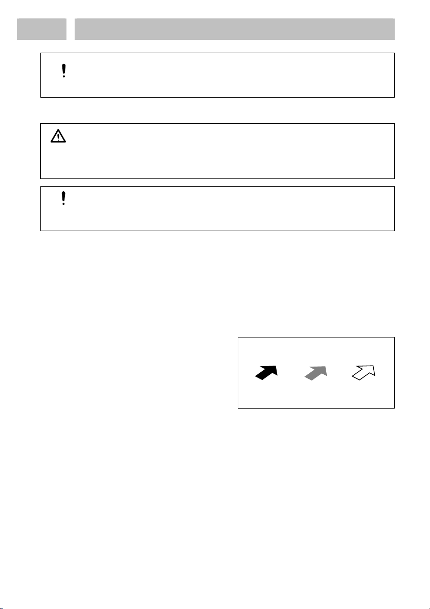
Instruction steps in the illustrations are indicated with arrows.
When several instruction steps are
indicated in an illustration, the shading
of the arrow has the following meaning:
Black arrow = 1st step
Grey arrow = 2nd step
White arrow = 3rd step
Notice!
As a result of technical development, the illustrations and descriptions in this
operating manual can deviate in detail from the actual unit delivered.
1.2 Items Supplied
1 Benchtop Peristaltic Dispenser 98548 1 Applicator Nozzle Ø 1.9 mm
1 Manual Applicator (Nozzle not
included)
1 Applicator Nozzle Ø 2.4 mm
1 Lubricant, Oil
1 Operating Manual 1 Feedline Set, black and clear,
1 Applicator Nozzle Ø 1.2 mm
1 Applicator Nozzle Ø 1.5 mm
different sizes, length of each 1 m

5
1
Please observe the following
1.3
Field of Application (Intended Use)
The Benchtop Peristaltic Dispenser 98548 provides volumetric dispensing of non-
thixotropic materials such as cyanoacrylates, anaerobics and UV products up to a
viscosity of 5,000 mPas without the need of compressed air. It can be used at manual
and semi-automatic workplaces.
For better dispensing results order the Needle Variety Kit 97262. In the needle kit
dispensing needles with different sizes are included.
1.4
For Your Safety
For safe and successful operation of the unit, read these instructions completely. The
manufacturer cannot be held responsible for damage or injury of any kind because of
misuse or improper application or because of failure to observe safety instructions or
warnings.
Be sure to retain this manual for future reference.
Refer to the technical data sheet of the assigned adhesive under the address
www.loctite.com or request the technical data sheet and the safety data sheet (acc. to
the EC Directive 91/155/EC) for the LOCTITE product used at
HenkelKGaA
+49 89 92 68 11 67 for English version of data sheets;
089-92 68 11 22 for German version of data sheets.
Or
Henkel Corporation
1001 Trout Brook Crossing
Rocky Hill, CT 06067, USA
Follow unconditionally the INSTRUCTIONS of these data sheets!
While under warranty, the unit may be repaired only by an authorized Henkel
service representative.
Warning!
If chemical products are not properly handled, damage to health can result!
Observe general safety regulations for the handling of chemicals!
Observe manufacturer’s instructions!
Request a safety data sheet for the LOCTITE®-product used!
Removing, by-pass or putting out of operation of the safety devices can result in
damage to health and to the unit and is therefore prohibited!
Damage to the power cord or the housing can result in contact with live electrical
parts.
Check the power cord and the unit before each use.
If the power cord or the unit is damaged, do not operate!
Replace a damaged power cord with a new one.
The unit may be opened and repaired only by an authorized service personal.
Do not touch the pump, rolling parts and the rotor’s inner parts while the pump is
working.
Check the tube before each use and replace a damaged tube with a new one. Do not
use unspecified tube for the roller.
When inner rotor is stuck with liquids, please send it immediately for repairing.
6
2
Description
2.1 Operating Elements and Connections
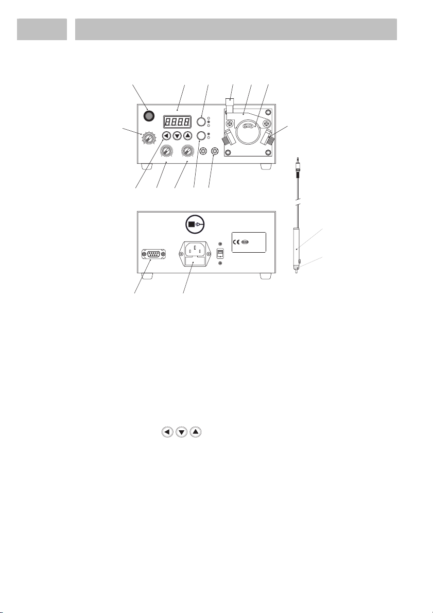
1
Power Switch - LED Lamp signals that the switch is on.
2
Operation Mode Switch R.C. Mode - The Remote Control Mode.
TimerMode- Time range: ~ 99.99 sec.
Cont.Mode- Continuous operation.
3
Speed Adjustment Knob - Adjust the deposit size (0 ~ 10).
4
Vacuum Adjustment Knob - The suck-back of the adhesive after dispensing.
5
Vacuum Delay Timer - Adjustable within 0 ~ 3 sec.
6
Start Interface - Finger switch connection. A higher-ranking controller can
also start the dispensing cycle.
7
Timer Buttons - To adjust dispense time from 0.01 ~ 99.99 sec.
8
Timer Display - 4-digits display.
9
CCW/CW Switch - CCW: Counterclockwise / CW: Clockwise.
10
Guide Lock - To fix the tube guide.
11
Tube Guide - To support a tube installed in the roller.
12
Pump Head - To extract liquids from a tube.
13
Tube Holder with locking knobs - To hold tube.
14
Power Connection with Fuse T1A fast-acting.
15
Start/Ready Signal Interface - The optional footswitch 97201 is connected
here. It is also the output for the READY signal.
16
Manual Applicator with Finger Switch - Length of PTFE tube: 1 m.
17
Applicator Nozzle - different sizes are available, see Section 7.1.
18
PTFE-Tube - (not shown) different sizes are available, see Section 7.1.
13
12
3
45 67
8
9
10 11 12
TIMER
CONT.
R.C
CW
CCW
MODE
VACUUM
0
SPEED
010
POWER
4
2
6
8
V.INT
10 0 10
OUT
DRIV
TIME DISPLAY
IN
14
15
FOOT SWITCH
D-81925 Mü}nchen
Rocky Hill, CT 06067, USA
1001 Trout Brook Crossing
Henkel Corporation
Madein Korea
(Placefor serial no.)
110/230VAC, 50/60 Hz
Henkel Loctite Deutschland GmbH
Arabellastr. 17 Fusefor 110 VAC - ????
powerconsumption: 10 W
Itemno: 98548
Fusefor 230 VAC - ????
AC Power 16
17
220V
Power Select

7
2
Description
2.2
Theory of Operations
The Benchtop Peristaltic Dispenser transfers low viscosity liquids by pressure
displacement applied by a turning rotor against a tube carrying the material. Usually
these pumps are chosen because the liquids are hazardous or difficult to work with
and it is advisable to limit operator contact. Another reason is that peristaltic pumps
are air free.
Dispense outputs can be timed from 0.01 - 99.99 seconds with flow speeds from
0.01-6 ml/min using PTFE tubing. The pump is bi-directional allowing suck-back
after dispense to prevent dripping of the fluid.
When dispensing UV adhesives use only black tubing. This avoids curing of the
adhesive in the tube.
The amount of product dispensed is controlled by:
– The dispensing time.
– The size of the used feedline.
– The speed of the drive.
– The size of the dispensing needle.
Various sizes of PTFE tubes, the corresponding applicator nozzles and dispensing
needles are available, see section 7.1.
3
Technical Data
Power supply 100-240 V AC ± 10%, 50/60 Hz
Power Consumption ~0.3 A
Fuse T1A fast-acting (Glass type, 5 x 20 mm)
Dispensing time range 0.01 - 99.99 sec
Rotor speed Up to max. 120 rpm (CW/CCW)
Flow rate 0.01 - 6 ml/minute with feedline
Direction of rotation of the drive Clockwise (CW) - Counterclockwise (CCW)
Operating Temperature +5°C - +50°C (+41°F -122°F)
Relative Humidity Max. 80%
Weight ~3 kg
prior to removing cover.
Unplug power cord
WARNING:
98548
TIMER
CONT.
R.C
CW
CCW
MODE
VACUUM
0
SPEED
0 10
POWER
4
2
6
8
V.INT
10 0 10
OUT
DRIV
TIME DISPLAY
IN
190 mm
7.46"
81 mm
3.2"
98 mm
3.85"
171 mm
6.73"
210 mm
8.25"
8
4
Setup and Operation
4.1 Environmental Conditions
– Keep product feedlines as short as possible. The shorter the feedline the smaller
the specific resistance and the lower the dispensing pressure can be.
– Avoid kinking of feedlines.
– Typically, the product feedline should not be longer than 2 m.
– Keep all fittings tight.
– No direct sunlight; no UV light!
– No condensing humidity.
– No splash water.
– Indoor use only.
– Use in areas of an altitude up to 2000 m (6,550 ft)
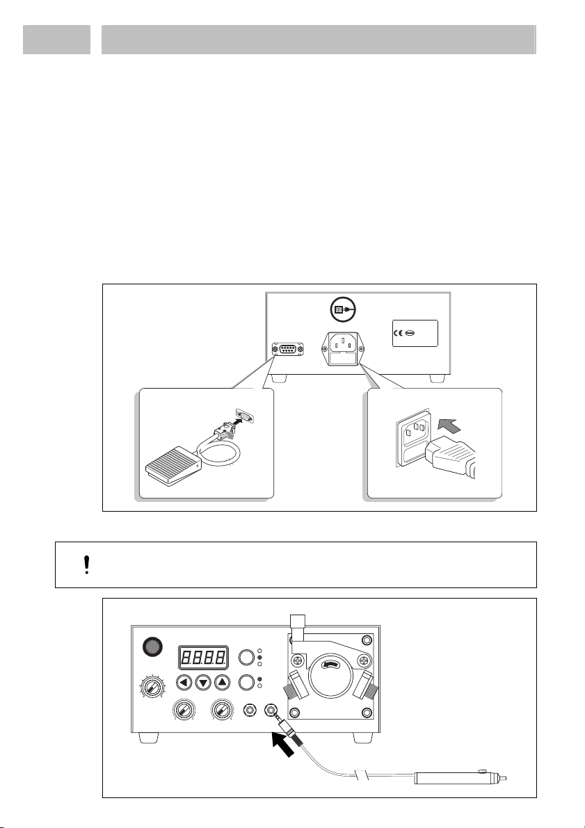
4.2 Connecting the Unit
Foot Switch (optional) and Power Cord
Manual Applicator Finger Switch
Caution!
Switch off the unit when connecting the finger switch!
TIMER
CONT.
R.C
CW
CCW
MODE
VACUUM
0
SPEED
0 10
POWER
4
2
6
8
V.INT
10 0 10
OUT
DRIV
TIME DISPLAY
IN
FOOT SWITCH
D-81925 Mü}nchen
Rocky Hill, CT 06067, USA
1001 Trout Brook Crossing
Henkel Corporation
Madein Korea
(Placefor serial no.)
110/230VAC, 50/60 Hz
Henkel Loctite Deutschland GmbH
Arabellastr. 17
Fusefor 110 VAC - ????
powerconsumption: 10 W
Itemno: 98548
Fusefor 230 VAC - ????
AC Power
Foot Switch

9
4
Setup and Operation
4.3
Setup and Operation
4.3.1
Mounting the Feedline to the Dispenser
Selector Chart Feedline - Nozzle
Nozzle Orifice
1.2 1.5 1.9 2.4
Feedline 865068 837760 837759 841976
1.0x0.3 1109147 – –
1087219 – –
1.4x0.3 1109318 – –
1001830 – –
1.7x0.4 1070736 – –
1109317 – –
2.4x0.4 1070735 – – –
1019162 – – –
If the feedline do not fit in the black signed nozzles then the grey signed nozzles can
be used as an alternative ( )
•As shown in the right graphic,
lift guide lock 10 and release
tube guide 11.
•Put the tube into the groove of the
right tube holder 13.
•Place the tube directly on the rollers.
•Put the tube into the groove of the left
tube holder 13.
•Press the white guide plate of tube
holder on both sides carefully against
tube and fix it with the locking knob.
•Pay attention that the tube is placed directly on the rollers.
The tube is guided and held in place with the tube guide 11.
•Slowly close the tube guide 11 and then turn the rotor manually.
Notice!
If the tube guide is tightened without turning the rotor, the shape of the rotor rolls
will be impressed and the tube will not be inserted evenly.
Always turn the rotor after closing the tube guide and press the tube guide 11 against
the rotor.
•Secure the tube guide 11 by following the 1st instruction step in reversed order.
If a thick tube is inserted and the rotor
stops,
•Lift guide lock 10.
•Unscrew the bigger lock grip from the
smaller one.
•Turn the screw counterclockwise one
revolution.
•Assemble both lock parts.

10
4
Setup and Operation
•Close the tube guide 11 as described above and start dispensing.
If product is not dispensed and the rotor stops again repeat steps above with a turn of
½ revolution counterclockwise. Repeat the steps till product is dispensed.
Pay attention that it is possible product is not dispensed and the rotor does not stop
then call the last step off.
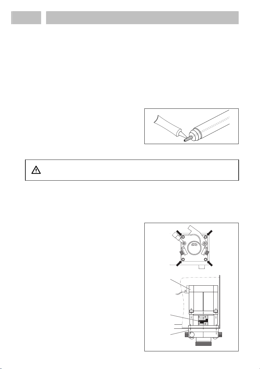
4.3.2 Mounting the Feedline to the Applicator
•Mount the applicator nozzle 17, which
corresponds to the used tube.
•Stretch the tube to reduce diameter.
•Cut the tube and press the remained
deformation together.
•Pull the tube through the applicator.
•Wait 2 minutes (1.) to let the tube
regain its shape.
•Cut the feedtube as shown is the right
graphic (2.).
•Install the required dispensing needle.
4.3.3 Mounting the Feedline to the Product Bottle
Dispensing Cyanoacrylate:
•Cut the nozzle of the bottle only as
much as it is necessary to insert the
tube.
Notice!
It is necessary to minimize moisture
access to the bottle that causes curing of
the CA.
Dispensing Anaerobic:
•Unscrew the dispensing cap.
•Cut the tube in the way described in the right graphic.
•Insert the tube into the bottle.
4.3.4 Setup of the Dispensing Quantity
TIMER MODE:
•Switch button Operation Mode Switch 2 to TIMER.
•With the button the digits of the display can be chosen separately.
•With the buttons and the required dispensing time can be chosen.
After a few seconds the adjusted time is set.
CA
~ 2 mm
1.
2.
~70 mm

11
4
Setup and Operation
•Switch button CCW/CW Switch 9to the direction of rotation, which the manual
applicator is connected to the tube.
Direction of rotation: CW – clockwise CCW – counter clockwise
•With the Speed Adjustment Knob 3choose a speed.
•Initiate a start to check the dispensed quantity.
If the dispensed quantity is too small:
•Increase the dispensing time and/or the speed of the drive. Check the dispensed
quantity again. Repeat this sequence until the desired dispensed quantity is
achieved.
If the dispensed quantity is too high:
•Decrease the dispensing time and/or the speed of the drive. Check the dispensed
quantity again. Repeat this sequence until the desired dispensed quantity is
achieved.
If the desired dispensed quantity is not within reach:
•Change the feedline to a smaller/bigger size and repeat the above steps.
R.C. MODE:
•Switch button Operation Mode Switch 2 to R.C.
The dispensing takes place as long as:
– The foot switch is pressed,
– The finger switch is pressed or
– A start signal from a higher-ranking controller is present.
CONT. MODE:
•Switch button Operation Mode Switch 2to CONT.
Caution!
Switch to this mode only when
– The manual applicator 16 with dispensing nozzle is placed at the dispensing
position or
– A cup is placed under the nozzle.
After 1 sec. the unit automatically starts and runs continuously!
4.4
Shutdown
•Switch off the dispenser.
4.5
Return to Operation
•Switch on the dispenser.
Caution!
Be careful when returning to operation in cont. MODE.
1 sec after switching on the unit the dispensing starts automatically!
The manual applicator 16 with dispensing nozzle should be placed at the dispensing
position or a cup is placed under the nozzle.
12
5
Cleaning and Changing
5.1 General
Clean the roller with a dust free tissue or towel.
Lubricate the rollers of the pump head once or twice a week. Lubrication will help
prolong tube life. Use silicone oil Loctite 8021 (for Europe) or an adequate oil.
Lifetime of the Feedline:
The PTFE tube should be replaced periodically. The lifetime of the tube will vary
depending of the rotation speed, frequency of use, etc. The user should determine
how often to replace the tube according to their need.
At adjustments „Speed 5“ and „CCW“ (pump head turns right) the lifetime of the
PO feedline is >100 h, the PTFE feedline >200 h. If the velocity will be increased
the lifetime is proportionally reduced and vice versa.
•When dispensing Cyanoacrylates
apply a small amount of silicon grease
to the applicator nozzle 17 to prevent
needle bonding.
5.2 Changing the Pump Head
Warning!
Disconnect power supply before opening the housing!
•Remove the tube.
•Remove the 8 screws of the top cover.
•Lift off the cover.
Notice!
Pay attention to the ground connection inside the cover.
•Disconnect earth cable.
•Remove the screws of the pump head.
•Hold the drive A.
•Remove the pump head 12 from the
drive.
•Assemble the pump head in reverse
order.
Notice!
Pay attention to the coupling B. Do not
forget this part when mounting the new
pump head.
Silicon grease
A
B
12
13
6
Troubleshooting
Type of malfunction Possible causes Correction
– Plug is not firmly
connected.
•Connect the plug firmly.
– The power switch is set
to off.
•Switch on the unit.
– Fuse is open. •Replace the fuse with
new one (1A).
Pump does not move.
– Speed dial is set to 0. •Dial to accelerate speed.
– Tube is not properly set
in a groove.
•Insert the tube
appropriately.
– Shape of rotor is
impressed on tube.
•Reset tube and turn rotor
while closing Tube
Guide.
Liquid does not dispense.
– Tube is not specified
for the machine type.
•Use specified tube.
– Guide is not properly
set.
•Set the guide properly.
– Guide support bolt is
not firmly tightened up.
•Tighten the bolt up
firmly.
7
Annex
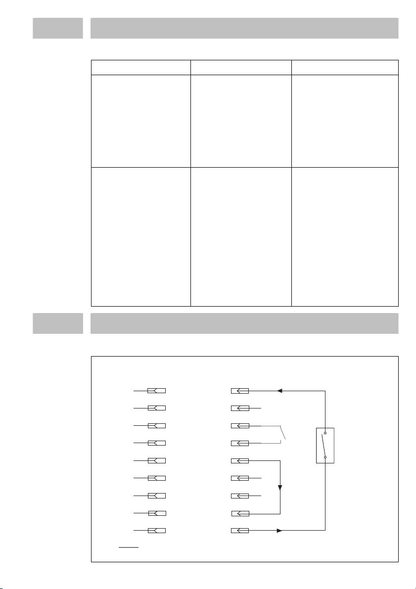
7.1
XS 1 Interface
1
2
3
4
5
6
7
8
9
S1
1
2
1
2
3
4
5
6
7
8
9
0 VDC
Start A
Pot. 0 VDC
Controller Footswitch
+24 VDC
End of
Cycle
Connections on
p
in 3 and 4 have to be made se
p
ratel
y
!

14
7
Annex
7.2 Accessories and Spare Parts
Pos. No. Description Type No. Order Code No.
– Foot Switch (Replacement)..............................................
.
97201 88653
– Standard Pump Head (Replacement) ...............................
.
989401 841977
– Manual Applicator Assembly (Replacement) ..................
.
989400 846483
17 Applicator Nozzle Ø 1.2 mm ...........................................
.
989937 865068
Applicator Nozzle Ø 1.5 mm ...........................................
.
989402 837760
Applicator Nozzle Ø 1.9 mm ...........................................
.
989403 837759
Applicator Nozzle Ø 2.4 mm ...........................................
.
989404 841976
18 Tubing, black, ID 2.4 x 0.4 mm (OD 3.2), 20 m..............
.
8953001 1070735
Tubing, clear, ID 2.4 x 0.4 mm (OD 3.2), 20 m...............
.
8953182 1019162
Tubing, black, ID 1.7 x 0.4 mm (OD 2.5), 20 m..............
.
8953000 1070736
Tubing, clear, ID 1.7 x 0.4 mm (OD 2.5), 20 m...............
.
8953185 1109317
Tubing, black, ID 1.4 x 0.3 mm (OD 2.0), 20 m..............
.
8953184 1109318
Tubing, clear, ID 1.4 x 0.3 mm (OD 2.0), 20 m...............
.
8954866 1001830
Tubing, black, ID 1.0 x 0.3 mm (OD 1.6), 20 m..............
.
8953183 1109147
Tubing, clear, ID 1.0 x 0.3 mm (OD 1.6), 20 m...............
.
8953142 1087219
– Needle Variety Kit ...........................................................
.
97262 218288
– Syringe & Applicator Holder...........................................
.
98501 756316
– Silicon Grease 6g Tube....................................................
.
997569 88722
7.3 Declaration of Conformity
Declaration of Conformity
The Manufacturer
according to the EC regulations
Henkel KGaA
Standort München
Gutenbergstr. 3
D-85748 Garching b. München
declares that the unit designated in the following is, as a result of its design and construction, in accordance
with the European regulations, harmonized standards and national standards listed below.
Designation of the unit Benchtop Peristaltic Dispenser Type 98548
Unit number 769914
Applicable EC Regulations EC Directive for Low Voltage 73/32/EEC. 93/68/EEC
EC Directive for Electro-Magnetic Compatibility
89/336/EEC, including changes 91/263/EC, 92/31/EC and
93/68/EC
Applicable harmonized standards EN 61010-1 :2001, EN 50081-2 :1993 (Class A),
EN 61000-3-2 :2000, EN 6100-3-3 :1995,
EN 6100-6-2 :1999
Date/Manufacturer’s signature
10/25/2007 (Dr. W. Fleischmann)
For changes to the unit that were not approved by Loctite, this declaration loses its validity.

15
Inhaltsverzeichnis
1
Bitte beachten Sie............................................................................................... 16
1.1
Hervorhebungen .................................................................................................. 16
1.2
Lieferumfang ....................................................................................................... 16
1.3
Einsatzbereich (Bestimmungsgemäße Verwendung)........................................... 17
1.4
Zu Ihrer Sicherheit............................................................................................... 17
2
Gerätebeschreibung........................................................................................... 18
2.1
Bedienelemente und Anschlüsse ......................................................................... 18
2.2
Funktionsbeschreibung........................................................................................ 19
3
Technische Daten............................................................................................... 19
4
Einstellung und Inbetriebnahme...................................................................... 20
4.1
Umgebungsbedingungen ..................................................................................... 20
4.2
Anschließen des Gerätes...................................................................................... 20
4.3
Einstellung und Inbetriebnahme .......................................................................... 21
4.3.1
Einlegen des Produktschlauches in das Gerät...................................................... 21
4.3.2
Montieren des Produktschlauches an das Handdosierventil ................................ 22
4.3.3
Montieren des Produktschlauches an die Produktflasche .................................... 22
4.3.4
Einstellung der Dosiermenge............................................................................... 22
4.4
Außerbetriebnahme ............................................................................................. 23
4.5
Wiederinbetriebnahme......................................................................................... 23
5
Reinigen und Auswechseln................................................................................ 24
5.1
Allgemeines......................................................................................................... 24
5.2
Auswechseln des Pumpenkopfes......................................................................... 24
6
Beseitigung von Störungen................................................................................ 25
7
Anhang ............................................................................................................... 25
7.1
Steckerbelegung XS 1 ......................................................................................... 25
7.2
Zubehör- und Ersatzteile...................................................................................... 26
7.3
Konformitätserklärung......................................................................................... 26
16
1
Bitte beachten Sie
Wichtig!
Die Bedienungsanleitung vor Inbetriebnahme des Gerätes unbedingt lesen und
verstehen!
1.1 Hervorhebungen
Gefahr!
Verweist auf Sicherheitsvorschriften und fordert Vorsichtsmaßnahmen, die den
Betreiber des Gerätes oder andere Personen vor Verletzungs- oder Lebensgefahr
schützen.
Achtung!
Hebt hervor, was getan oder unterlassen werden muss, um das Gerät oder andere
Sachwerte nicht zu beschädigen.
Hinweis!
Gibt Empfehlungen zum besseren Handhaben des Gerätes bei Bedien- und
Einstellvorgängen sowie Pflegearbeiten.
Die fett gedruckten Zahlen im Text beziehen sich auf die entsprechende
Positionsnummer in der Abbildung auf Seite 18.
•Der Punkt hebt einen Handlungsschritt hervor.
– Der Gedankenstrich hebt eine Aufzählung hervor.
Handlungsschritte in den Abbildungen sind durch Pfeile gekennzeichnet.
Werden mehrere Handlungsschritte in
einer Abbildung dargestellt, bedeutet
ein:
Schwarzer Pfeil = 1. Handlungsschritt
Grauer Pfeil = 2. Handlungsschritt
Weißer Pfeil = 3. Handlungsschritt
Hinweis!
Bedingt durch die technische Entwicklung können die Abbildungen und
Beschreibungen in dieser Bedienungsanleitung vom tatsächlich ausgelieferten
Gerät in Details abweichen.
1.2 Lieferumfang
1 Peristaltische Schlauchpumpe 98548 1 Auftragsdüse Ø 1,9 mm
1 Handdosierventil (Düse nicht
enthalten)
1 Auftragsdüse Ø 2,4 mm
1 Schmieröl
1 Bedienungsanleitung 1 Produktschlauch-Set, schwarze und
1 Auftragsdüse Ø 1,2 mm
1 Auftragsdüse Ø 1,5 mm
naturfarbene in verschiedene Größen,
Länge à 1 m

17
1
Bitte beachten Sie
1.3
Einsatzbereich (Bestimmungsgemäße Verwendung)
Die Peristaltische Schlauchpumpe 98548 wird zur volumetrischen Dosierung von
nicht thixotropen verwendet. Dazu gehören Cyanacrylate, anaerobe Klebstoffe und
UV-Produkte bis zu einer Viskosität von 5.000 mPas. Das Gerät benötigt keine
Druckluftversorgung und kann an Handarbeitsplätzen und halbautomatischen
Arbeitsplätzen eingesetzt werden. Um bessere Dosierergebnisse zu erzielen kann das
Dosiernadel-Set 97262 bestellt werden. Darin sind Dosiernadeln verschiedener
Länge und Durchmessers enthalten.
1.4
Zu Ihrer Sicherheit
Für den gefahrlosen und erfolgreichen Einsatz des Gerätes diese Anleitung
vollständig lesen. Der Hersteller kann nicht für Schäden verantwortlich gemacht
werden, die infolge der Nutzung abweichend vom bestimmungsgemäßen Gebrauch
oder der Nichtbeachtung von Sicherheitshinweisen oder Warnungen verursacht
werden. Bewahren Sie diese Anleitung nach Durchsicht griffbereit auf.
Informationen über das eingesetzte LOCTITE®Produkt finden Sie in dem
entsprechenden Techn. Datenblatt unter der Adresse www.loctite.com oder fordern
Sie hier das Techn. Datenblatt und das Sicherheitsdatenblatt (gem. EU Richtlinie
91/155/EU) an:
HenkelKGaA
+49 89 92 68 11 67 für die englische Version der Datenblätter;
089-92 68 11 22 für die deutsche Version der Datenblätter.
ANWEISUNGEN in diesen Datenblättern unbedingt befolgen!
Innerhalb der Gewährleistungsfrist darf das Gerät nur vom autorisierten Henkel-
Service geöffnet und repariert werden.
Warnung!
Wenn chemische Produkte nicht ordnungsgemäß gehandhabt werden, kann dies zu
Gesundheitsschäden führen!
Allgemeine Sicherheitsvorschriften für den Umgang mit Chemikalien beachten!
Anweisungen des Herstellers beachten!
Sicherheitsdatenblatt des eingesetzten LOCTITE®-Produktes anfordern!
Entfernen, Überbrücken oder Außerkraftsetzen der Sicherheitseinrichtungen kann zu
Gesundheitsschäden bei Personen und zu Schäden am Gerät führen und ist deshalb
verboten!
Bei Schäden am Netzkabel oder Gehäuse kann es zu Berührungen spannungs-
führender Teile kommen.
Vor jedem Gebrauch Netzkabel und Gerät kontrollieren.
Bei beschädigtem Netzkabel oder Gerät nicht in Betrieb nehmen!
Das beschädigte Netzkabel durch ein neues ersetzen.
Das Gerät darf nur von autorisiertem Servicepersonal geöffnet und repariert werden.
Pumpe, umlaufende Teile und Rotorinnenteile nicht berühren, während die Pumpe
arbeitet.
Vor jedem Gebrauch Schlauch kontrollieren und den beschädigten Schlauch durch
einen neuen ersetzen Nur spezifizierte Schläuche für den Pumpenkopf verwenden.
Wenn der innere Rotor mit flüssigen Werkstoffen verklebt ist und festsitzt, bitte
sofort zur Reparatur einschicken.

18
2
Gerätebeschreibung
2.1 Bedienelemente und Anschlüsse
1 Netzschalter – LED-Lampe signalisiert, dass der Schalter eingeschaltet ist.
2 Wahlschalter Betriebsart
„R.C.“ Betriebsart Fernsteuerung – Ferngesteuerter Betrieb
„Timer“ Betriebsart – Zeitbereich: ~ 99.99 sec.
„Cont.“ Betriebsart – Dauerbetrieb
3 Drehzahl-Reglerknopf – Einstellung der Abgabemenge (0 ~ 10).
4 Vakuum- Regler – Rücksaugung des Klebstoffes nach dem Dosieren
5 Vakuum- Nachlaufzeitregler – regelbar zwischen 0 ~ 3 sec.
6 Start-Schnittstelle – Anschluss für Fingerschalter. Der Dosiervorgang kann
auch mit einem übergeordneten Steuergerät gestartet werden
7 Timer-Tasten
- zum Einstellen der Dosierzeit von 0.01 ~ 99.99 s.
8 Zeitanzeige – 4-stellige Anzeige
9 „CCW/CW“-Schalter – „CCW“: Gegen Uhrzeigersinn / „CW“: Im
Uhrzeigersinn
10 Führungs-Feststeller – zum Fixieren der Schlauchführung
11 Schlauchführung – zum Führen eines auf der Rolle montierten Schlauches
12 Pumpenkopf – zum Fördern von Flüssigkeiten aus einem Schlauch
13 Schlauchhalter mit Feststellknöpfen – Zum Befestigen des Schlauches
14 Netzanschluss mit Sicherung T1A flink
15 Schnittstelle Signal Start/Bereit – hier wird der Fußschalter 97201
angeschlossen. Dies ist auch der Ausgang für die Bereitmeldung
16 Handdosierventil mit Fingerschalter – Länge des PTFE-Schlauchs: 1 m
17 Auftragsdüse – verschiedene Größen lieferbar, siehe Abschnitt 7.1.
18 PTFE-Schlauch – (keine Abb.) diverse Größen lieferbar, siehe Abschnitt 7.1.
13
12
3
45 67
8
9
10 11 12
TIMER
CONT.
R.C
CW
CCW
MODE
VACUUM
0
SPEED
010
POWER
4
2
6
8
V.INT
10 0 10
OUT
DRIV
TIME DISPLAY
IN
14
15
FOOT SWITCH
D-81925 Mü}nchen
Rocky Hill, CT 06067, USA
1001 Trout Brook Crossing
Henkel Corporation
Madein Korea
(Placefor serial no.)
110/230VAC, 50/60 Hz
Henkel Loctite Deutschland GmbH
Arabellastr. 17
Fusefor 110 VAC - ????
powerconsumption: 10 W
Itemno: 98548
Fusefor 230 VAC - ????
AC Power 16
17
220V
Power Select

19
2
Gerätebeschreibung
2.2
Funktionsbeschreibung
Die Peristaltische Schlauchpumpe transportiert niedrigviskose Flüssigkeiten mittels
Druckverdrängung, ausgeübt über einen drehenden Rotor auf einen flüssigkeits-
führenden Schlauch. Gewöhnlich werden diese Pumpen gewählt, wenn
Flüssigkeiten gefährlich oder schwierig zu verarbeiten sind und es ratsam ist, das
Bedienungspersonal möglichst wenig in Kontakt damit zu bringen. Ein weiterer
Grund ist, dass peristaltische Pumpen ohne Druckluftversorgung arbeiten.
Dosierzeiten können von 0,01 – 99,99 Sekunden eingestellt werden, mit Fließ-
geschwindigkeiten von 0,01-6 ml/min beim Einsatz von PTFE-Schläuchen. Die
Pumpe arbeitet in zwei Richtungen und erlaubt so eine Rücksaugung gegen evtl.
Nachtropfen der Flüssigkeit.
Beim Dosieren von UV-Klebstoffen dürfen nur schwarze Schläuche verwendet
werden. So vermeidet man das Aushärten des Klebstoffes in den Schläuchen.
Die Dosiermenge ist abhängig von:
– der Dosierzeit,
– der Größe des eingesetzten Produktschlauches,
– der Drehzahl,
– der Größe der Dosiernadel.
PTFE-Schläuche sind in verschiedenen Größen lieferbar, ebenso die entsprechenden
Auftragsdüsen und Dosiernadeln – siehe Abschnitt 7.1.
3
Technische Daten
Stromversorgung 100-240 V AC ± 10%, 50/60 Hz
Leistungsaufnahme ~0.3 A
Sicherung T1A flink (Glasrohr, 5 x 20 mm)
Dosierzeitbereich 0,01-99,99 sec
Rotor-Drehzahl Bis max. 120 U/min (im/gegen den Uhrzeigersinn)
Fließgeschwindigkeit 0,01 – 6 ml/Minute mit Produktschlauch
Drehrichtung im Uhrzeigersinn (CW) – gegen den Uhrzeigersinn (CCW)
Betriebstemperatur +5°C - +50°C (+41°F -122°F)
Rel. Luftfeuchtigkeit Max. 80%
Gewicht 3 kg
prior to removing cover.
Unplug power cord
WARNING:
98548
TIMER
CONT.
R.C
CW
CCW
MODE
VACUUM
0
SPEED
0 10
POWER
4
2
6
8
V.INT
10 0 10
OUT
DRIV
TIME DISPLAY
IN
190 mm
7.46"
81 mm
3.2"
98 mm
3.85"
171 mm
6.73"
210 mm
8.25"

20
4
Einstellung und Inbetriebnahme
4.1 Umgebungsbedingungen
– Produktschläuche so kurz wie möglich halten. Je kürzer der Produktschlauch,
desto kleiner der spezifische Widerstand und desto niedriger der erforderliche
Dosierdruck.
– Produktschlauch nicht knicken.
– Im typischen Fall sollte der Produktschlauch nicht länger als 2 m sein.
– Alle Anschlüsse sorgfältig festziehen.
– Direkte Sonnen- und UV-Lichteinstrahlung vermeiden!
– Keine kondensierende Feuchtigkeit.
– Kein Spritzwasser.
– Nur für die Verwendung im Innenbereich.
– Einsetzbar in Höhenlagen bis 2000 m NN (6,550 ft)
4.2 Anschließen des Gerätes
Fußschalter und Netzkabel
Fingerschalter für Handdosierventil (optional)
Achtung!
Beim Anschließen des Fingerschalters das Gerät ausschalten!
TIMER
CONT.
R.C
CW
CCW
MODE
VACUUM
0
SPEED
0 10
POWER
4
2
6
8
V.INT
10 0 10
OUT
DRIV
TIME DISPLAY
IN
FOOT SWITCH
D-81925 Mü}nchen
Rocky Hill, CT 06067, USA
1001 Trout Brook Crossing
Henkel Corporation
Madein Korea
(Placefor serial no.)
110/230VAC, 50/60 Hz
Henkel Loctite Deutschland GmbH
Arabellastr. 17
Fusefor 110 VAC - ????
powerconsumption: 10 W
Itemno: 98548
Fusefor 230 VAC - ????
AC Power
Foot Switch
Table of contents
Languages:
Other Henkel Dispenser manuals

Henkel
Henkel OSI Service manual

Henkel
Henkel Loctite 97008 User manual

Henkel
Henkel LOCTITE 97130 User manual

Henkel
Henkel Loctite EQ HD12 manual

Henkel
Henkel Loctite EQ RC40 User manual

Henkel
Henkel Loctite Shot Miser User manual

Henkel
Henkel Loctite 98427 User manual

Henkel
Henkel Loctite User manual

Henkel
Henkel Loctite 97631 User manual

Henkel
Henkel Loctite RB10 User manual
Popular Dispenser manuals by other brands

BOWMAN
BOWMAN CL003-0111 manual

SIKA
SIKA Power Cure operating instructions

Silver King
Silver King Majestic SK12MAJ Technical manual and replacement parts list

Franke
Franke F3Dn Twin Service manual

HURAKAN
HURAKAN HKN-MT1 manual

STIEBEL ELTRON
STIEBEL ELTRON UltraHot Plus Operation and installation instructions


