3
Electric Shock Hazard
Disconnect power before servicing.
Use 12-gauge solid copper wire.
Electrically ground oven.
Failure to follow these instructions can result
in death, re, or electrical shock.
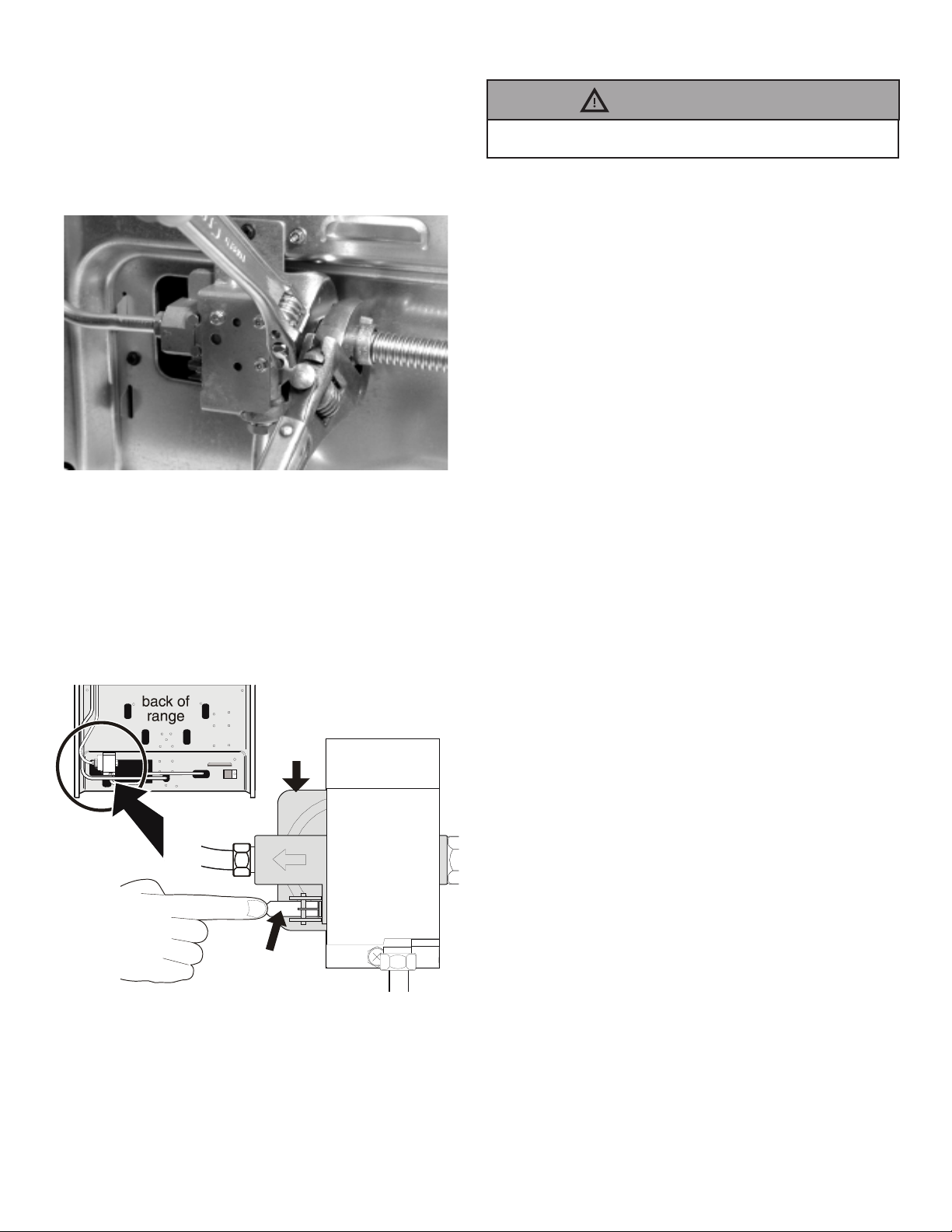
Provide proper fuel type
Before proceeding: Your range is factory preset to
operate on natural gas. If L.P. conversion is needed,
contact your local L.P. Gas provider for assistance.
The L.P. conversion kit may be located on the
lower rear back panel of the range. If no L.P. kit is
provided, contact your product dealer to obtain the
correct L.P. conversion kit.
Important notes to the installer
• Read all instructions contained in these
installation instructions before installing range.
• Remove all packing material from the oven
compartments before connecting the gas and
electrical supply to the range.
• Observe all governing codes and ordinances.
• Be sure to leave these instructions with the
consumer.
• All materials used in construction of cabinets,
enclosures, and supports surrounding the
product must have a temperature rating above
194°F (90°C).
Important notes to the consumer
• Keep these instructions with your User manual
for future reference.
• Be sure your range is installed and grounded
properly by a qualied installer or service
technician.
Special instructions for appliances installed in the
State of Massachusetts:
This appliance can only be installed in the State of
Massachusetts by a Massachusetts licensed plumber
or gas tter. When using a exible gas connector, it
must not exceed 3 feet (36 inches) in length. A “T”
handle type manual gas valve must be installed in
the gas supply line to this appliance.
IMPORTANT SAFETY
INSTRUCTIONS
• Installation of this range must conform with local
codes or, in the absence of local codes, with the
National Fuel Gas Code ANSI Z223.1—latest
edition when installed in the United States.
• When installed in a manufactured (mobile)
home, installation must conform with the
Manufactured Home Construction and Safety
Standard, Title 24 CFR, Part 3280 [formerly the
Federal Standard for Mobile Home Construction
and Safety, Title 24, HUD (Part 280)] or, when
such standard is not applicable, the Standard for
Manufactured Home Installations, ANSI/NCSBCS
A225.1, or with local codes.
• This range has been design certied by CSA
International. As with any appliance using gas
and generating heat, there are certain safety
precautions you should follow. You will nd them
in the User manual, read it carefully.
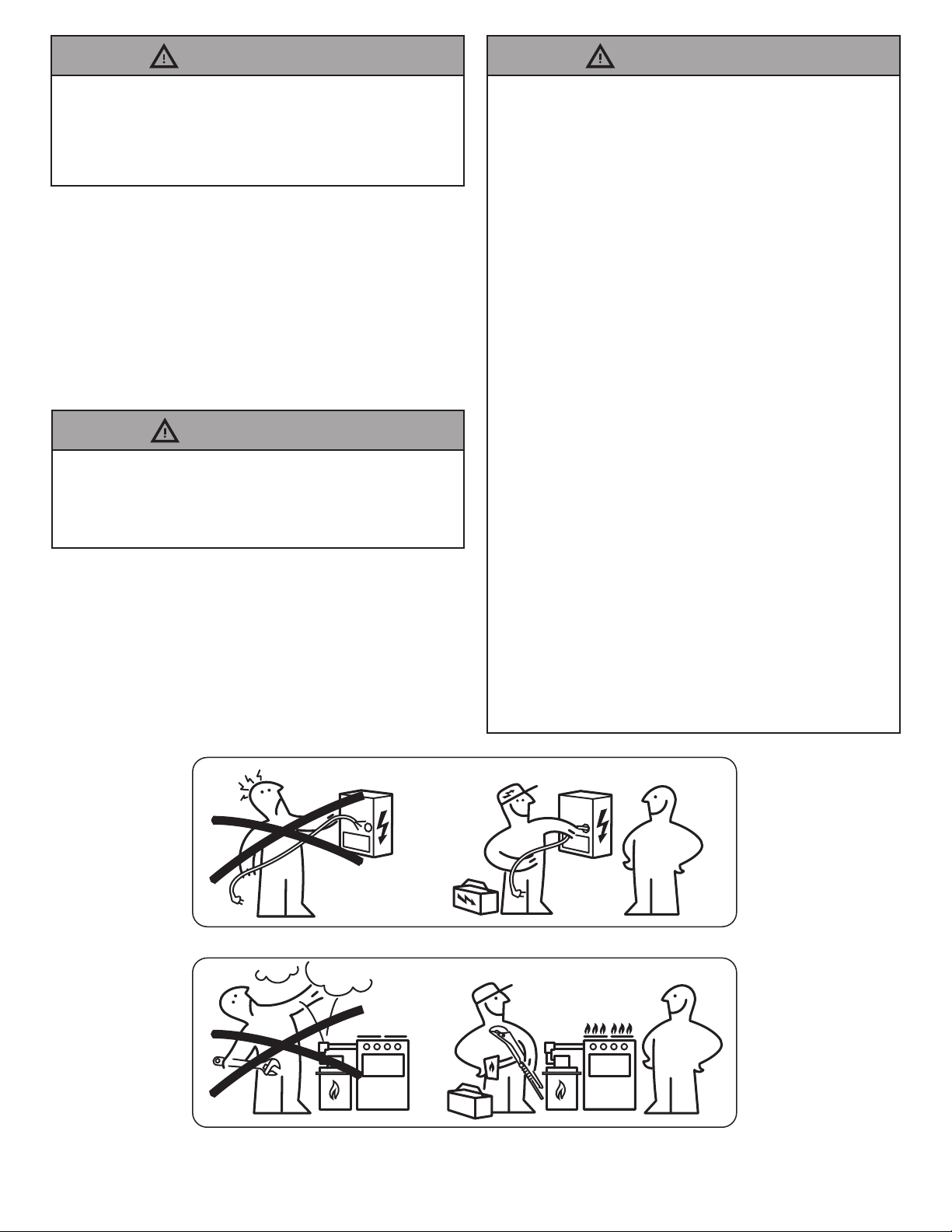
• Be sure your range is installed and grounded
properly by a qualied installer or service
technician.
• This range must be electrically grounded in
accordance with local codes or, in their absence,
with the National Electrical Code ANSI/NFPA
No .70—latest edition when installed in the
United States. See Grounding Instructions on
page 11.
• Before installing the range in an area covered
with linoleum or any other synthetic oor
covering, make sure the oor covering can
withstand heat at least 90°F above room
temperature without shrinking, warping or
discoloring. Do not install the range over
carpeting unless you place an insulating pad or
sheet of 1/4-inch thick plywood between the
range and carpeting.
• Make sure the wall coverings around the range
can withstand the heat generated by the range.
• Do not obstruct the ow of combustion air at the
oven vent nor around the base or beneath the
lower front panel of the range. Avoid touching
the vent openings or nearby surfaces as they
may become hot while the oven is in operation.
This range requires fresh air for proper burner
combustion.
• Air curtain or other overhead range hoods,
which operate by blowing a downward air ow
on to a range, shall not be used in conjunction
with gas ranges other than when the hood and
range have been designed, tested and listed
by an independent test laboratory for use in
combination with each other.