manuals.online logo
Brands
  1. Home
  2. •
  3. Brands
  4. •
  5. Ikegami
  6. •
  7. Security Camera
  8. •
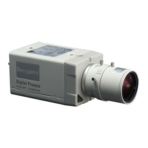
  9. Ikegami ICD-808 User manual

Ikegami ICD-808 User manual

Ikegami Tsushinki Co.,Ltd.
Setting Procedure
for ICD-808/P, ICD-828/P, ICD-848/P
(SET UP MENU)
Setting procedure for ICD-808/P, ICD-828/P, ICD-848/P (SET UP MENU)
-1/10 -
[1] Setting Switches
Set up of these camera are operated by pressing following switches,
which are located at rear panel of camera or on RCU-701 remote set up unit.
Switch name Main function
UP switch (U): Setting item selection (up)
DOWN switch (D): Setting item selection (down)
RIGHT switch (R): Setting change and setting item selection
(right)
LEFT switch (L): Setting change and setting item selection
(left)
ENTRY switch (E): Setting mode call on/off, setting entry
[2] Setting Procedure of OSD (On Screen Display).
Hold the E switch down and the SET UP MENU (Fig.1) appears as OSD on the monitor
screen.
1. CAMERA ID (camera identification)
(1) Camera ID on/of SET UP MENU
Move the cursor to the position shown in Fig.1
by using U and D switches CAMERA ID OFF
Using the R and L switches, select the CAMERA ID
DAY/NIGHT AUTO
itemfrom ON to OFF. SHUTTER OFF
(2) Entry of ID codes LIGHT CONT. LENS
When it is selecting ON, press the E switch. GAIN AGC
The screen of Fig.2 appears.WHITE BAL. ATW1
SYNC INT
MENU LOCK OFF
EXIT CANCEL RESET
Fig.1
ID EDIT
ABCDEFGHIJKLMNOPQ
Characters to choose from RSTUVWXYZéìèîêíçë
0123456789:+-/.•
ID display line ••••••••••••••••
çè
SPACE CLEAR
RET EXIT POS
Fig.2
SET UP
U
LR
D E
Setting procedure for ICD-808/P, ICD-828/P, ICD-848/P (SET UP MENU)
-2/10 -
Select characters for an ID code. Enter the characters one by one in the ID display line
(marked with the cursor in Fig.2). Up to 16 characters are acceptable.
(a) Position the start point of the ID display line:
Select çor èsymbol and press the R or L switch.
The cursor mark will move.
(b) Selecting characters:
Use the U,D,R and L switches.
(c) Entering the characters in the ID display line:
Press the E switch.
(d) Giving blanks:
Select the SPACE and press E switch. The cursor mark will move.
(e) Clearing all the characters from the ID display line:
Select the CLEAR and press the E
(3) Setting of display position
Setting the POS and press the E switch. The ID code will appear on the regular screen.
Using the U,D,R and L switches, move the ID code to any position.
Press the E switch and the display position will be determined and the screen show in
Fig2 will appear again.
(4) Use the RET or EXIT to end the setting.
2. DAY/NIGHT set up (ICD-848/P only)
(1) Setting a DAY/NIGHT function SET UP MENU
Move the cursor to the position shown in Fig.3
by using U and D switches. CAMERA ID OFF
Using the R and L switches, select DAY/NIGHT DAY/NIGHT AUTO
item from AUTO, B/W, COLOR and REMOTE. SHUTTER OFF
(2) AUTO mode LIGHT CONT. LENS
This mode is used for automatic changing from GAIN AGC
COLOR to B/W under the condition of changing to
WHITE BAL. ATW1
low light and from B/W to COLOR under the SYNC INT
conditions of returning to normal light. MENU LOCK OFF
Select AUTO from the DAY/NIGHT item. And press
the E switch. The screen of Fig.4 appears.EXIT CANCEL RESET
Fig.3
Adjust the level of COLOR to B/W by using L and R
DAY/NIGHT AUTO
switches. Move to B/W? COL by using the U and
D switches and adjust the level of B/W to COLOR
by using the L and R switches. SWITCHED LEVEL
Move to the bottom line by using the U and COL èB/W L ••••| •••Η
D switch. B/W èCOL L ••••| •••Η
Select RET to go back to SET UP MENU or select
EXIT. And press the E switch. RET EXIT
Fig.4
Note: Switch Level Adjustment
-1. Setup of COL èB/W
When you adjust the switched level of COL èB/W, it switches from color to B/W in brighter
conditions, as you movethe marker to H direction. But it switches from color to B/W in darker
conditions, as you movethe marker to L. direction
Setting procedure for ICD-808/P, ICD-828/P, ICD-848/P (SET UP MENU)
-3/10 -
The marker is explained as follows
Default condition at factory
COL èB/W L ••••|•••H
Video Level Area Gain Area
AGC/HYPER-AGC MAX.
In the default condition at factory, it is set up to switch Color –B/W at the point of
AGC/HYPER-AGC Gain maximum, when the marker location is center.
In case of moving the marker from center to H direction, it switches at smaller gain.
(It switched form color to B/W at brighter conditions.)
In case of setting the marker to H direction from center, it is in the control area by
Gain. So brightness of video on the monitor screen does not changed.
But as the gain level is different, the noise level is different. So if you want to switch
with small noise condition, move the marker to H direction.
In case of moving the marker to L direction, it switches with smaller video level.
(It switches from color to B/W at darker conditions.)
-2. Setup of B/W èCOL
When you adjust the switched level of B/W èCOL, it switches from B/W to color in darker
conditions, as you move the marker to Ldirection. In case of it switches between color and
B/W continuously (hunting) under the certain lighting conditions, move the marker to H
direction.
(3) REMOTE mode
This mode is used for changing by remote signal. Select REMOTE from the DAY/NIGHT item.
And press the E switch. The screen of Fig.5 appears.
Connect remote cable to remote terminal at rear DAY/NIGHT REMOTE
panel. Remote control is by MAKE signal of BREAK
signal.
Select CONTROL SIGNAL item MAKE or BREAK.
CONTROL SIGNAL MAKE
Move to bottom line by using the U and D switch.
Select RET to go back to SET UP MENU or select
EXIT. And press the E switch.
RET EXIT
Fig.5
3. SHUTTER
(1) Setting an electronic shutter function SET UP MENU
Move the cursor to the position show in Fig.6
by using U and D switches. CAMERA ID OFF
Using the R and L switches, select SHUTTER item
DAY/NIGHT AUTO
from OFF, 1/100(PAL:1/60), 1/125, 1/250, 1/500, SHUTTER OFF
1/1000, 1/2000, 1/4000, 1/10000 and VARIABLE. LIGHT CONT. LENS
(2) VARIABLE shutter mode the E switch. GAIN AGC
This mode is used for setting VARIABLE shutter WHITE BAL. ATW1
Speed from 1/60(PAL:1/50) to 1/100000. SYNC INT
Select VARIABLE. And press the E switch. MENU LOCK OFF
The screen of Fig.7 appears.
EXIT CANCEL RESET
Fig.6
Setting procedure for ICD-808/P, ICD-828/P, ICD-848/P (SET UP MENU)
-4/10 -
Adjust variable shutter speed by using the L and R
VARIABLE SHUTTER
Switches. You can see it’schanging on the screen.
Move to the bottom line by using the U and
D switch. SPEED L ••••| •••Η
Select RET to go back to SET UP MENU or select
1/569.5
EXIT. And press the E switch.
RET EXIT
Fig.7
4. LIGHT CONTROL
(1) Selecting a light control mode SET UP MENU
Move the cursor to the position shown in Fig.8
by using U and D switches. CAMERA ID OFF
Using the R and L switches, select LIGHT DAY/NIGHT AUTO
CONTROL item from LENS and AES. SHUTTER ---
In case of using VIDEO iris lens or DC iris lens, LIGHT CONT. AES
select LENS, and select DC or VIDEO by dip switch
GAIN AGC
at side panel. WHITE BAL. ATW1
Connect auto iris connector of auto iris lens to the
SYNC INT
connector at side panel of this camera. MENU LOCK OFF
EXIT CANCEL RESET
Fig.8
DC iris level is also adjustable. LIGHT CONTROL
When an auto iris connector of DC iris lens is
connected, LIGHT CONTROL item is forced to be BACKLIGHT CMP. OFF
LENS. When the cursor is at LENS, press E switch.
The screen of Fig.9 appears.
Move the cursor to IRIS LEVEL by using the U and IRIS LEVEL L ••••|•••Η
D switch. And adjust IRIS LEVEL by using L and
R switch RET EXIT SPOT BLC
Fig.9
Move to the bottom line by using the U and D switch. Select RET to go back to SET UP MENU or
select EXIT. And press the E switch.
In case of using manual iris lens with AES, select AES. But in case of using manual iris
lens and controlling light condition by manual iris, select LENS.
(2) BLC (Back Light Compensate) mode.
You can select BLC item from ON, OFF and SPOT. When the cursor is the position of
LENS or AES, press the E switch. The screen of Fig.10 appears.
(a) BLC OFF LIGHT CONTROL
Select OFF by using the L and R switches.
Move to the bottom line by using the U and BACKLIGHT CMP. OFF
D switch.
Select RET to go back to SET UP MENU or select
EXIT. And press the E switch.
RET EXIT SPOT BLC
Fig.10
Setting procedure for ICD-808/P, ICD-828/P, ICD-848/P (SET UP MENU)
-5/10 -
(b) BLC ON
Select ON by using the L and R switches. The screen changes to Fig.11.
Move to BLC LEVEL by using the U and D LIGHT CONTROL
switches, and adjust by using the L and
R switches. BACKLIGHT CMP. ON
Move to WIDE BLC by using the U and D BLC LEVEL L ••••|•••Η
switches, and select ON or OFF by using the L and
WIDE BLC OFF
R switches.When WIDE BLC is ON, it adjusts
gamma and knee optimally for high ligting area.
RET EXIT SPOT BLC
Fig.11
Move to bottom line by using the U and D switch. Select RET to go back to SET UP MENU
or select EXIT. And press the E switch.
(c) BLC SPOT
It can select the sensing area for BLC calculation. The sensing area can be selected only
one area. Its sensing level can be adjustable too.
Select SPOT by using the L and R switches. The screen changes to Fig.12.
Move to BLC LEVEL by using the U and D LIGHT CONTROL
switches, and adjust by using the L and
R switches. BACKLIGHT CMP. SPOT
Move to bottom line by using the U and BLC LEVEL L ••••|•••Η
D switch. Select SPOT BLC by using the L and
R switches.
And press the E switch.
The screen of Fig.13 appears.RET EXIT SPOT BLC
Fig.12
Move cursor to ⇐, ⇑, ⇒and ⇓by using the U,
D, L andR switches, and press E switch.
Selected arrow key blinks when active. ⇑
as Fig 14.
⇐RET ⇒
⇓
Fig.13
Move selected area by using the U and D
or the L and R switches.
Press E switch for being active. ⇑
Select other arrow key by using the U, D, L and R
switches to select other direction of area. ⇐RET ⇒
Or select RET by using the U, D, L and R switches.
And press the E switch to go back LIGHT ⇓
CONTROL menu.
The screen of Fig.12 appears.
Fig.14
Select RET to go back to SET UP MENU or select EXIT.
Setting procedure for ICD-808/P, ICD-828/P, ICD-848/P (SET UP MENU)
-6/10 -
5. GAIN
Move the cursor to the position shown in Fig 15. SET UP MENU
By using the L and R switches select GAIN item
from AGC, HYPER-AGC, LOW, MID and HIGH. CAMERA ID OFF
The AGC entry keeps on the AGC function of max.
DAY/NIGHT AUTO
20 dB, but the HYPER-AGC entry keeps on the SHUTTER OFF
AGC function of max. 30 dB. LIGHT CONT. AES
The LOW entry keeps AGC function off (0dB). GAIN AGC
The MID(10dB) and HIGH(20dB) entries provide
WHITE BAL. ATW1
for fixed gains. SYNC INT
When the DAY/NIGHT entry is the AUTO mode, MENU LOCK OFF
the GAIN entry is forced to AGC or HYPER-AGC.
EXIT CANCEL RESET
Fig.15
6. WHITE BALLANCE
Move the cursor to the position shownin Fig 16. By using the L and R switches select
WHITEBALLANCE item from ATW1, ATW2, AWC and MANUAL.
(1) ATW1 entry SET UP MENU
The white balance is automatically followed up
(with color temperature of 26000-6000°K). CAMERA ID OFF
When no sodium lighting is issued, keep the DAY/NIGHT AUTO
automatic white balance in this mode. SHUTTER OFF
LIGHT CONT. AES
GAIN AGC
WHITE BAL. ATW1
SYNC INT
MENU LOCK OFF
EXIT CANCEL RESET
Fig.16
(2) ATW2 entry SET UP MENU
The white balance is automatically followed up
in the range from sodium lighting and sunlight
CAMERA ID OFF
(with color temperature of 2000-6000°K). DAY/NIGHT AUTO
When sodium lighting is used, keep the automatic SHUTTER OFF
white balance in this mode. LIGHT CONT. AES
Note that in the ATW2 mode, reddish objects may
GAIN AGC
look less brilliant. WHITE BAL. ATW2
SYNC INT
MENU LOCK OFF
EXIT CANCEL RESET
Fig.17
Setting procedure for ICD-808/P, ICD-828/P, ICD-848/P (SET UP MENU)
-7/10 -
(3) AWC entry SET UP MENU
The characters “AWC PUSH”start blinking in the
position as shown in Fig.18. Now shoot a
white target and press the E switch. CAMERA ID OFF
DAY/NIGHT AUTO
The white balance is now adjusted. SHUTTER OFF
(When the E switch is pressed, the PUSH LIGHT CONT. AES
characters change to “- --“ first and then “SET”GAIN AGC
and back to “PUSH”again. With the PUSH on WHITE BAL. AWCPUSH
screen, it is possible to make setting again.) SYNC INT
MENU LOCK OFF
EXIT CANCEL RESET
Fig.18
(4) MANUAL entry SET UP MENU
Select manual and press E switch.
The screen of Fig.20 appears.CAMERA ID OFF
DAY/NIGHT AUTO
SHUTTER OFF
LIGHT CONT. AES
GAIN AGC
WHITE BAL. MANUAL
SYNC INT
MENU LOCK OFF
EXIT CANCEL RESET
Fig.19
Adjust R GAIN by using the L and R switches. WHITE BALANCE
Move to B GAIN by using the U and D switches.
Adjust B GAIN by using the L and R switches. R GAIN L •| ••••••Η
Move to the bottom line by using the U and B GAIN L •••|••••Η
D switch.
Select RET to go back to SET UP MENU or select
EXIT. And press the E switch.
RET EXIT
Fig.20
7. SYNCHRONIZATION
Move the cursor to the position shownin Fig.21. SET UP MENU
Using the R and L switches, enter INT or LL.
in the SYNC item. CAMERA ID OFF
(1) INTERNAL LOCK entry DAY/NIGHT AUTO
Select INT. The camera is put in the internal SHUTTER OFF
sync mode. LIGHT CONT. AES
(2) LINE LOCK entry GAIN AGC
Select LL and press the E switch. WHITE BAL. ATW1
The screen of Fig.22 appears. SYNC INT
MENU LOCK OFF
EXIT CANCEL RESET
Fig.21
Setting procedure for ICD-808/P, ICD-828/P, ICD-848/P (SET UP MENU)
-8/10 -
Adjust the COARSE by using the L and R switches.
SYNC LL
Move to FINE by using the U and D switches.
And adjust by using the L and R switches. COARSE 0 DEG
Move to the bottom line by using the U and FINE L |•••••••Η
D switches.
Select RET to go back to SET UP MENU or select
EXIT. And press the E switch.
RET EXIT
Fig.22
Notes: The LL setting cannot be made in the following cases.
-DC type camera (no line lock signal input)
-NTSC system model with 50Hz power frequency or PAL system model with 60Hz
power frequency.
(3) GENLOCK SET UP MENU
When a camera inputs external sync signal from
GENLOCK IN connector at rear panel, CAMERA ID OFF
SYNC item is forced to select EXT VBS or EXT VS.
DAY/NIGHT AUTO
When you select EXT VBS and press the E switch,
SHUTTER OFF
the screen of Fig.24 appears.LIGHT CONT. AES
GAIN AGC
WHITE BAL. ATW1
SYNC EXTVBS
MENU LOCK OFF
EXIT CANCEL RESET
Fig.23
Adjust the H PHASE by using the L and R SYNC VBS
switches. Move to SC COARSE by using the U and
D switches. And adjust by using the L and R H PHASE L •••••| ••Η
switches. Move to SC FINE by using the U and D SC COARSE 0 DEG
Switches. And adjust by using the L and R SC FINE L ••|•••••Η
switches.
RET EXIT
Fig.24
Move to the bottom line by using the U and D switches. Select RET to go back to SETUP MENU or
select EXIT. And press the E switch.
When you select EXT VS and press the E switch, SYNC VS
the screen of Fig.25 appears.
Adjust H PAHSE by using the L and R switches. H PHASE L •••••| ••Η
Move to the bottom line by using the U and
D switches.
Select RET to go back to SET UP MENU or select
EXIT. And press the E switch.
RET EXIT
Fig.25
Setting procedure for ICD-808/P, ICD-828/P, ICD-848/P (SET UP MENU)
-9/10 -
8. MENU LOCK
The menu lock function is provided to protect the settings from unintentional changes.
(1) LockingSET UP MENU
Move the cursor to the position shown in Fig.26.
Press the E switch. When the menu is locked,
CAMERA ID OFF
the “ON”in the MENU LOCK is video-reversed.DAY/NIGHT AUTO
As shown in Fig.27 SHUTTER OFF
LIGHT CONT. AES
GAIN AGC
WHITE BAL. ATW1
SYNC INT
MENU LOCK OFF
EXIT CANCEL RESET
Fig.26
(2) Operation SET UP MENU
Once the menu has been locked, only the EXIT
Instruction is effective. Any other instructions are CAMERA ID OFF
not accepted. DAY/NIGHT AUTO
(3)Unlocking SHUTTER OFF
Press the following switches in this order: LIGHT CONT. AES
U –R –D –L –U –D -E GAIN AGC
If a wrong key has been pressed halfway, do it WHITE BAL. ATW1
Again from the beginning. SYNC INT
MENU LOCK ON
EXIT CANCEL RESET
Fig.27
Setting procedure for ICD-808/P, ICD-828/P, ICD-848/P (SET UP MENU)
-10/10 -
9. SPECIAL MENU
Move to the cursor to the EXIT position in the
setting SET UP MENU
menu as shown in Fig.28.
Hold down the R and L switches at once until CAMERA ID OFF
the screen as shown in Fig.29 will show up. DAY/NIGHT AUTO
SHUTTER OFF
LIGHT CONT. AES
GAIN AGC
WHITE BAL. ATW1
SYNC INT
MENU LOCK OFF
EXIT CANCEL RESET
Fig.28
(1) CHROMA SPECIAL MENU V.1.06
Used to adjust the chroma level. Shifting toward
the H position increasesthe level.
CHROMA L ••••| •••Η
(2) DETAIL DETAIL L •••••|••Η
Used to adjust the details correction level. The H PEDESTAL L ••••|•••Η
D
irection makes images sharper and the L direction
MATRIX A MODE
Softer. LANGUAGE ENGLISH
(3) PEDESTAL
Used to adjust the pedestal level. RET EXIT
Shifting towardH position increases the level. Fig.29
(4) MATRIX
Select A MODE for the normal condition. When using camera indoors or under fluorescent light, B
MODE is recommended.
(5) LANGUAGE (PAL only)
Select ENGLISH menu or FRENCH menu
Move to the bottom line by using the U and D switches. Select RET to go back to SET UP MENU
or select EXIT. And press the E switch.

Other manuals for ICD-808

1

This manual suits for next models

1

Other Ikegami Security Camera manuals

Ikegami HDL-40 User manual

Ikegami

Ikegami HDL-40 User manual

Ikegami IEN-T01 User manual

Ikegami

Ikegami IEN-T01 User manual

Ikegami PCS-400P Series User manual

Ikegami

Ikegami PCS-400P Series User manual

Ikegami ICD-809 User manual

Ikegami

Ikegami ICD-809 User manual
Ikegami PCS-418 User manual

Ikegami

Ikegami PCS-418 User manual

Ikegami ICD-D11-2812 System manual

Ikegami

Ikegami ICD-D11-2812 System manual

Ikegami IPD-Q38 User manual

Ikegami

Ikegami IPD-Q38 User manual

Ikegami MKC-230HD User manual

Ikegami

Ikegami MKC-230HD User manual

Ikegami IPD-VR11 User manual

Ikegami

Ikegami IPD-VR11 User manual

Ikegami ITC-510 User manual

Ikegami

Ikegami ITC-510 User manual

Ikegami ICD-8024 User manual

Ikegami

Ikegami ICD-8024 User manual

Ikegami ISD-A31 User manual

Ikegami

Ikegami ISD-A31 User manual

Ikegami ICD-38 User manual

Ikegami

Ikegami ICD-38 User manual

Ikegami CTC-4700 User manual

Ikegami

Ikegami CTC-4700 User manual

Ikegami ICD-31 User manual

Ikegami

Ikegami ICD-31 User manual

Ikegami ICD-376 User manual

Ikegami

Ikegami ICD-376 User manual

Ikegami ICD-608 User manual

Ikegami

Ikegami ICD-608 User manual

Ikegami ICD-B3 User manual

Ikegami

Ikegami ICD-B3 User manual

Ikegami ICD-49 User manual

Ikegami

Ikegami ICD-49 User manual

Ikegami ICD-40 User manual

Ikegami

Ikegami ICD-40 User manual

Ikegami SKC-145T2 Installation and operation manual

Ikegami

Ikegami SKC-145T2 Installation and operation manual

Ikegami ICD-4620 User manual

Ikegami

Ikegami ICD-4620 User manual

Ikegami ICD-42A User manual

Ikegami

Ikegami ICD-42A User manual

Ikegami ISD-A30 User manual

Ikegami

Ikegami ISD-A30 User manual

Popular Security Camera manuals by other brands

Vivotek PZ7111 Specifications

Vivotek

Vivotek PZ7111 Specifications

Canon VB-H730F Mk II installation guide

Canon

Canon VB-H730F Mk II installation guide

Digital Watchdog DWC-V1362DIR manual

Digital Watchdog

Digital Watchdog DWC-V1362DIR manual

TRASSIR TR-D2281WDIR4 user manual

TRASSIR

TRASSIR TR-D2281WDIR4 user manual

JAGER PRO M.I.N.E. Operator's manual

JAGER PRO

JAGER PRO M.I.N.E. Operator's manual

Vitek Transcendent VTC-TNB5RME quick start guide

Vitek

Vitek Transcendent VTC-TNB5RME quick start guide

Grundig GD-CI-BC2626T quick start guide

Grundig

Grundig GD-CI-BC2626T quick start guide

TRENDnet TV-IP325PI user guide

TRENDnet

TRENDnet TV-IP325PI user guide

Speco O4VT1 quick start guide

Speco

Speco O4VT1 quick start guide

ZOSI C696 quick start guide

ZOSI

ZOSI C696 quick start guide

Infinova V1723 Operation/programming

Infinova

Infinova V1723 Operation/programming

Speco VLEDT1HG/W Series quick start guide

Speco

Speco VLEDT1HG/W Series quick start guide

Messoa NIC830-HN5 instruction manual

Messoa

Messoa NIC830-HN5 instruction manual

Telecom Behnke 20-2906A-IP instructions

Telecom Behnke

Telecom Behnke 20-2906A-IP instructions

Grandstream Networks GXV3611IR_HD Quick installation guide

Grandstream Networks

Grandstream Networks GXV3611IR_HD Quick installation guide

Panasonic WV-CW590A installation guide

Panasonic

Panasonic WV-CW590A installation guide

chinavasion ES-HD-10D-IP851 Quick installation & user manual

chinavasion

chinavasion ES-HD-10D-IP851 Quick installation & user manual

Kedacom IPC4X1 Series user manual

Kedacom

Kedacom IPC4X1 Series user manual

manuals.online logo
manuals.online logoBrands
  • About & Mission
  • Contact us
  • Privacy Policy
  • Terms and Conditions

Copyright 2025 Manuals.Online. All Rights Reserved.