Ikelite DS160 User manual

Digital
Substrobe
D 160
TTL
Full
-2
-1
-3
-4
ReadyLight
Fuel
Gauge
3
2
1
Test
O
On
On
w /Lite
4060.1
Note: Please read all instructions before using this product.

2
TABLE OF CONTENT
IKELITE D 161 UB TROBE............3
Specifications ......................................3
Introduction ..........................................4
Starting Out..........................................4
Strobe Compatibility ............................4
Strobe Power ......................................4
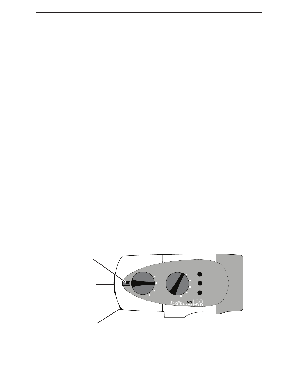
DS160 Substrobe ................................5
Overview of DS160 Features ..............5
Becoming Familiar ..............................5
OPENING AND CLO ING ..................6
Opening the Strobe..............................6
Recharge the Battery Pack ..................6
Closing the Strobe ..............................6
Opening and Closing (Illustrations)......7
Li-ion BATTERY PACK ......................8
Charging the Li-ion Pack......................8
Charging with NiMH Charger ..............8
CAUTION ............................................8
FLA H DIFFU ER ..............................9
Using the Diffuser ................................9
Diffuser Installation and Removal ........9
ARM Y TEM / TROBE MOUNT ..10
Ikelite Arm Systems ............................10
Ikelite Mounts ......................................10
TROBE CONNECTION ....................11
Strobe Connection (Illustration) ..........12
U ING A HARD-WIRED TROBE ..13
U ING A HARD-WIRED TROBE
WITHOUT TTL ....................................13
U ING A A LAVE TROBE............14
AIMING THE TROBE........................15
WITCHE / FUEL GAUGE ..............16
On/Off Switch ......................................16
Fuel GAUGE ........................................17
Confidence Signal................................17
Firing Mode Switch ..............................17
TROBE READY LIGHT ....................18
Strobe Ready Light and TTL Housing..18
Camera Ready Light ..........................18
Triggered via Sync Cord ......................18
Triggered via Slave Sensor..................18
MART CHARGER 4067.1 ................19
Smart Charger 4067.1 ........................19
Smart Charger Components ................19
Smart Charger Indicator Light..............19
Charging with NiMH Charger ..............19
CAUTION ............................................19
RECOMMENDATION ........................20
Visual Inspections ................................20
Insurance ............................................20
Tips ......................................................20
Lubricant ..............................................20
MAINTENANCE ..................................21
Cleaning and Storage ..........................21
TROUBLE HOOTING ........................22
Strobe Will Not Fire..............................22
FLOODING ..........................................23
LIMITED WARRANTY ........................23
RETURN PRODUCT FOR ERVICE..23
PRODUCT REGI TRATION ...Back Page

D 160 PECIFICATION
CE - Compliant with applicable EU directives
Complies with FCC part 15, subpart B, ection 15.109 for Class “B” Products
p e c i f i c a t i o n s
Battery Pack ............................................ ....... Li-ion module, 7.4v, 4500mAh
Weight .................................................... ....... 2.5 lb (1130g)
Size.......................................................... ....... 9.6 cm dia. x 17.9 cm....... 3.75" dia. x 7"
Depth Rating............................................ ....... 90m - 300 feet
t r o b e
Energy Rating.......................................... ....... 160 watt-sec
Recycle Time .......................................... ....... 1.4 sec
Angle of Coverage .................................. ....... 90 degrees....... 100 degrees with diffuser
Guide # (ISO 100) feet ............................ ....... 76 surface - 38 underwater
Guide # meters ........................................ ....... 24 surface - 12 underwater
Color Temperature .................................. ....... 4800 degrees elvin
Full Power Flashes .................................. ....... 450 flashes per full charge
Firing Modes............................................ ....... TTL, Full, 9 fractional powers
Modeling Light
Modeling Light ........................................ ....... 5-watt LED
TTL
Full
-2
-1
-3
-4
ReadyLight
Fuel
Gauge
3
2
1
Test
O
On
On
w /Lite
Switch Lock
Toggle
Li-ion Battery Pack
DS160 Strobe Head
3
IKELITE D 160 UB TROBE

INTRODUCTION
Thank you for purchasing an Ikelite Substrobe. Ikelite brings over 50 years of underwater
photographic and lighting experience to the strobe market. Ikelite Substrobes are
designed and built in the USA by Ikelite to suit both the professional and the amateur
photographer.
The purpose of a strobe is to illuminate the subject and assist the camera in taking vivid
pictures. The Ikelite DS160 Substrobe is equally suited for general and wide-angle
photography, covering up to a full 100° angle with a diffuser.
This strobe is everything you need for stunning photos.
TARTING OUT
Before using the Ikelite DS160 Substrobe, please read this owner’s manual thoroughly
and retain it for future reference. Ikelite recommends becoming familiar with the
features and functions of the Ikelite DS160 Substrobe above water before trying the
camera and strobe in the water. And, if you have not yet done so, it is suggested that you
read your camera’s owner’s manual as well.
TROBE COMPATIBILITY
The DS160 Substrobe is compatible with all Ikelite TTL systems and current digital
cameras, as well as all older TTL film cameras including the Nikonos system. A variety of
sync cords, sensors, and TTL adapters are available to connect to almost any camera
system currently on the market.
TROBE POWER
The DS160 recycles in a quick 1.4 sec from full discharge. When fired at a fractional
power — whether in TTL or manual mode — the strobe recycles virtually instantaneously.
Number of flashes per full charge will increase dramatically in most cases when using in
TTL mode with a compatible camera system. The powerful DS160 is adjustable in 10
half-stop increments for precise control over your exposure when used in manual mode.
IKELITE D 160 UB TROBE (cont.)
4

5
IKELITE D 160 UB TROBE (cont.)
D 160 UB TROBE
The Ikelite DS160 strobe combines high intensity output and wide coverage angle
in a compact, versatile design. This strobe features 160 watt-sec. intensity and covers
a full 100° using the diffuser. Special soft-lite reflector provides rich reds, oranges, and
warmer flesh tones.
The Ikelite DS160 strobe is pre-flash compatible and operates with both traditional film
cameras and digital still cameras. Multiple firing modes are featured, including TTL/Auto
exposure.
The DS160 electronics are safely sealed separately from the battery pack. The industrial
grade Li-ion batteries recycle in an incredible 1.4 seconds and the Li-ion pack
is easily interchangeable with a spare unit. When in the “Batt w/Lite” position, the fuel
gauge references the remaining battery capacity. Aim the DS160 and illuminate your
subject's colors with the built-in modeling light / night diving light.
OVERVIEW OF D 160 FEATURE
• Separate power and firing mode switches.
• Interchangeable battery pack features industrial grade Li-ion batteries.
• LED fuel gauge approximates the remaining battery capacity.
• Visual ready light indicates when strobe has recycled.
• Female Ikelite bulkhead connector accepts different camera sync cords and the
EV-Controller 4100.6.
• Exposure guide label references recommended exposure settings.
• Separate diffuser provides softer lighting and wider coverage angle.
BECOMING FAMILIAR
Before using the Ikelite Substrobe, please read this owners manual thoroughly and retain
for future reference. We recommend that you become familiar with the features and
functions of the Ikelite Substrobe before trying the camera and strobe in the water. If you
have not done so, we also suggest reading your camera owner's manual.

OPENING THE TROBE
Turn the strobe OFF, and place the strobe face down on a flat surface.
Slide the locking lever out by either grasping the sides of the lever and pulling it out OR
use your thumb to apply slight pressure to the top of the lever and slide it out.
Flip the lever up and then rotate the lever counter-clockwise 90°. The internal spring
automatically pushes open the strobe. Lift the rear section off of the strobe front (See
illustrations on page 7). The rear section is the Li-ion battery pack for the strobe.
The Li-ion pack does NOT remain waterproof when removed from the strobe. Therefore,
we suggest keeping the open portion of the Li-ion pack pointed down while removing to
eliminate the possibility of water droplets falling inside. The Li-ion batteries remain
permanently secured inside the pack.
The front section of the DS160, which houses the main electronics, is safely sealed
separately from the Li-ion pack. The front section will remain waterproof when the Li-ion
pack is removed. However, avoid salt-water contact with the battery pins.
Damage/corrosion can cause a short circuit. DO NOT disassemble the strobe or the
Li-ion pack. We suggest storage of your strobe with the locking lever OPEN to allow any
hydrogen/air mixture to escape.
O-RING
The o-ring is located on the inside rim of the Li-ion pack. eep the o-ring and the sealing
surfaces clean. DO NOT stretch the o-ring when cleaning. It is not necessary to lubricate
the o-ring. Never use spray lubricant because it may crack the plastic.
RECHARGE THE BATTERY PACK
See "CHARGING THE Li-ion PAC " section for recharging information on page 8.
CLO ING THE TROBE
Make sure the power switch has been rotated to the off position.
Place the front of the strobe face down on a flat surface. Check that the o-ring and
sealing surfaces are clean; make sure the o-ring is positioned properly inside the rim of
the Li-ion pack. Place the locking lever in the open position (slide the lever out, flip the
lever up, and rotate the lever counterclockwise 90 degrees until it stops).
Align the front and rear sections of the strobe. Lower the Li-ion pack onto the front
section of the strobe. Proper alignment of the two sections is extremely important to
avoid possible damage to the internal components.
To seal the strobe, simply press down slightly on the rear of the Li-ion pack and rotate
the lever clockwise 90 degrees until it stops. Flip the lever down and then slide the lever
into the locked position to properly seal the strobe.
6
OPENING AND CLO ING

7
OPEN
RCD
INDPLS IN U.S.A.
UNLOCK
INDPLS IN U.S.A.
UNLOCK
Pull Out
Flip Up Rotate
OPENING AND CLO ING (CONT.)

CAUTION:
DO NOT use the older AULT charger, part
#BCW-306-125-01-03N, which has a green
power LED and yellow charge LED on the
charger front.
CHARGING THE Li-ion PACK WITH NiMH CHARGER
When recharging the Li-on Pack with an older NiMH
charger, a solid red LED indicates the Pack is
charging. When the LED is NOT lit, the Pack is
fully charged.
8
The 4060.1 DS160 comes standard with rechargeable Li-ion battery pack and flash
diffuser (page 9). The Li-ion battery pack requires 4067.1 Smart Charger (page 19), not
included except with certain strobe packages.
Rechargeable Li-ion battery pack 4067 is compatible only with Ikelite's DS160 and
DS161 strobe. The rear section of the strobe is the Li-ion battery pack for the strobe.
Additional Li-ion packs (rear sections) 4067 are available through an Ikelite dealer.
Battery pack is also compatible with older DS125 and DS160 strobes.
A fully charged Li-ion pack provides at least 450 full power flashes. It consists of six
sub-C-cell industrial grade Li-ion batteries.
The Li-ion pack does NOT remain waterproof when removed from the strobe.
Therefore, we suggest keeping the open portion of the Li-ion pack pointed down while
removing to eliminate the possibility of water droplets falling inside. The Li-ion
batteries remain permanently secured inside the pack. DO NOT disassem le the
Li-ion pack or charger.
The DS160 accepts the same 4066.5 NiMH module used on older DS161, DS160 and
DS125 Substrobes. If you intend to use an older battery pack on your new Substrobe,
please reference the notice dated 6/22/09 on the following webpage:
http://www.ikelite.com/we _pages/important.html.
Charger
Socket
Ring
Li-ion Module 4067
Li-ion BATTERY PACK 4067
CHARGING THE Li-ion PACK
Recharge the Li-ion pack after each use. Recharge the battery pack if the modeling light
dims or if the recycle time exceeds 8-10 seconds; batteries are nearly depleted. Recharge
the battery pack once every 12 months.

9
FLA H DIFFU ER 0591.3
Flash Diffuser
Installation Post
Diffuser
Cut-outs
D 160 trobe
Diffuser Retention Tab
Lanyard Holes
U ING THE DIFFU ER
The white diffuser can be secured to the front of the DS160 strobe when softer lighting
or a coverage angle of 100° is desired.
The diffuser reduces the DS160’s light intensity by one full f-stop.
DIFFU ER IN TALLATION AND REMOVAL
1. Position the Diffuser Cut-outs over the DS160 strobe’s Diffuser Retention Tabs.
2. Press down lightly until the diffuser is flush against the strobe face.
3. Rotate the Diffuser Installation Posts either direction until the Posts stop
against the strobe’s Diffuser Retention Tabs.
4. Reverse process to remove the Diffuser.
A lanyard or string can be attached to the diffuser by threading it through the two
Lanyard Holes near its edge. Attach the other end to the strobe to prevent
accidental loss.

10
IKELITE ARM Y TEM
Ikelite offers several arm choices compatible with the DS160. The arm and strobe mount
are NOT supplied with the strobe. For additional information go to www.ikelite.com
Caution: Ikelite arm systems are designed for underwater use. Be careful when
transporting the system above water since some camera trays and arm adjustments may
be unable to support the weight of the strobe(s) above water.
IKELITE MOUNT
ARM Y TEM / TROBE MOUNT
TTL
Full
-2
-1
3
-4
Fuel
Gauge
3
2
1
Test
O
On
On
w /Lite
An optional paddle-type or ball-type mount can be mounted to the underneath side of the
strobe. The mount slides into the strobe base and is secured with a screw (supplied with
optional mount). Make sure to slide the mount into the strobe base until it stops. Be
careful to not cross-thread the screw when tightening the mount. The DS160 Shroud can
be rotated slightly to gain better access to the strobe base with a screwdriver.
Although not necessary, you can apply a small amount of Ikelite lube around the screw
threads before attaching the strobe mount. Use Ikelite lube only which is supplied with the
DS161 strobe. This will reduce the possibility of seizing and allow removal of the screw
should the mount need to be removed. Removing the mount for long storage periods will
also reduce the possibility of seizing.
DS160 Shroud
Ball-Type Mount
“not included”
with DS160
Mount Screw
Strobe Base

11
The female Ikelite bulkhead connector permits different Ikelite sync cords or the Ikelite
EV manual controller sensor to be connected to the strobe. The sync cord or sensor relays
a signal from the camera to the substrobe that tells the DS160 when to flash.
The removable waterproof bulkhead cap seals the bulkhead connector when neither a
cord nor a sensor is connected to the DS160. The strobe’s bulkhead connection must be
sealed to remain waterproof (page 12).
Caution:
• Do not leave the sync cord or sensor connected to the camera or strobe
for prolonged periods as electrolysis could occur and make removal of the
equipment impossible.
• Do not disconnect the sync cord or sensor from the housing or strobe when
underwater or when wet. These items are not waterproof when disconnected.
• Make sure there is no debris on the sync cord o-ring and the sync cord connector
is aligned properly when attaching to the strobe bulkhead (page 12).
CONNECTION TO TROBE
To connect either a sync cord or sensor to the DS160 Substrobe, follow these instructions:
1. Turn the substrobe to OFF and make sure all components are dry. Clean and
lightly lubricate the stem o-ring and the bulkhead connector threads.
Check the o-ring for nicks or cuts.
2. Note the positioning of the receptacles and pins on the end of the cord. Properly
align the end of the cord and insert it into the strobe bulkhead connector.
When using the 4103.51 cord, which connects an Ikelite housing to an Ikelite
Substrobe, both cord ends are identical; either end can be connected to the
strobe.
3. The connector threads are very fine; do not cross thread. If it is difficult
to turn the knurled retaining ring on the cord or sensor, you are likely
cross-threading. This can make removal of the strobe or sensor impossible.
Hand-tighten the knurled retaining ring on the cord or sensor. Push the end of
the cord further into the bulkhead connector and continue to tighten the knurled
retaining ring. Do not use pliers or a tool when tightening. It could damage the
cord or strobe.
TROBE CONNECTION

12
Bulkhead
Connection
Retaining Ring
Stem O-ring
Blue Band
#4103.51 Ikelite Sync Cord
TROBE CONNECTION (CONT.)
D 160 trobe
Bulkhead Cap

13
For use with the following types of systems:
- Ikelite housings for digital cameras with external strobe connector but without TTL
conversion circuitry
- Non-Ikelite housings for digital cameras with Nikonos-style strobe connector
Connect the strobe using an appropriate Ikelite sync cord. The DS160 must be used in
manual exposure modes. Strobe output is not automatically adjusted for proper exposure
when set to TTL(Auto) mode.
U ING A A HARD-WIRED TROBE WITHOUT TTL
For use with the following types of systems:
- Ikelite housings for digital cameras with TTL conversion circuitry
- Ikelite housings for film cameras
- Nikonos V, RS cameras
- Non-Ikelite housings for digital cameras and compatible TTL adapter
Connect the strobe using an appropriate Ikelite TTL sync cord. Digital DSLR cameras
require the use of a Digital TTL sync cord. These cords are designated by a blue band at
one end. The DS160 may be used in TTL(Auto) or manual exposure modes.
TTL (thru-the-lens) exposure automatically compensates for aperture, distance and filters.
Because there's such a wide range of apertures and
subject distances, photographers wanting to easily
balance lighting and control close-up photographer
should select the TTL(Auto) exposure mode. When
the strobe fires, the camera reads the light and signals
the strobe to turn off when the exposure is correct.
Strobe output can be adjusted in TTL(Auto) mode
using either exposure compensation built into the
camera or an exposure compensation module in the
back of the housing (if applicable).
If an exposure compensation module is featured in the
back of the housing, strobe output may be controlled
manually while the strobe itself is left in TTL(Auto)
mode. In order to use the manual exposure modes on
the strobe itself, the housing module must be set in a
manual position.
When using a non-Ikelite TTL adapter or third party
conversion circuitry, please refer to the product's instructions for help in using the DS160
with this setup.
U ING A A TTL HARD-WIRED TROBE
Retaining Ring
Stem O-ring
Blue Band
Ikelite

14
U ING A A LAVE TROBE
For use with the following types of systems:
- Ikelite or non-Ikelite housings without external strobe connector
The EV Manual Controller 4100.6 is required to use the DS160 as a slave strobe. The
EV Controller watches the camera's built-in flash and triggers the strobe at the
appropriate time.
Set the DS160 mode switch to "TTL" to utilize the power settings on the EV Manual
Controller. If the DS160 is set to a manual exposure mode, the power settings of the EV
Manual Controller are ignored.
The camera must be set to a "forced flash" mode, usually designated by a lightning bolt,
in order for the DS160 to fire consistently in every photo. Both the camera's built-in flash
and the DS160 must recycle completely before taking another flash photo.
Most digital cameras fire one or more short preflashes to help the camera determine
focus, exposure and color balance. After the preflash(es), the camera's built-in flash fires
to illuminate the subject while the photo is taken. Both the EV Manual Controller and the
Substrobe DS160 are preflash compatible. The internal switches on the EV Controller
must be set properly for the DS160 to fire at the correct time. Refer to the EV Manual
Controller instruction manual for more information.
If the DS160 fires at the incorrect time resulting in a dark photo, the preflash setting is
most likely incorrect. Check both the preflash switch on the EV Controller and the
camera's exposure mode. Some digital
cameras such as the Canon G-series fire
a preflash in Auto, Program, shutter
priority and aperture priority modes, but
not manual exposure modes.
EV Manual Controller
Sync Cord connects
directly to DS160
Slave
Sensor

15
AIMING THE TROBE
AIMING THE TROBE
Use the modeling light to aim the strobe. Look thru the camera's viewfinder, and aim the
strobe so that the modeling light shines in the center of your picture area. If your subject
distance greatly changes, you should recheck the positioning of the strobe.
When using auto-focus cameras, the modeling light may be required in low light levels to
illuminate your subject to allow the camera to auto focus.
Modeling Light
D 160 trobe
Flash Tube

16
WITCHE / FUEL GAUGE
TTL
Full
-2
-1
3
-4
Fuel
Gauge
3
2
1
Test
O
On
On
w /Lite
Switch Lock
Battery
Compartment
The DS160 features separate switches for power on/off and firing modes. The arrow on
the switch points to the selected position.
ON/OFF WITCH
OFF: The horizontal switch position is OFF. The adjacent tab locks the switch in the OFF
position. To unlock, slide the tab away from the switch. Always turn the Substrobe OFF
before opening the strobe.
ON: There are two ON positions. Rotating the switch clockwise to the first ON position
turns on the power to the Substrobe. Further rotation of the switch clockwise to the
second ON position turns on both the power to the Substrobe and the modeling light.
TE T: Occasionally check the battery capacity by rotating the switch counter-clockwise
to the “Batt w/Lite” battery position and referencing the fuel gauge on the side of the
strobe. The “Batt w/Lite” battery position also turns ON the modeling light.
Fuel G auge
D 160 trobe

17
FUEL GAUGE
When the switch is rotated to the “Batt w/Lite” position, the fuel gauge on the side of the
strobe will display 0, 1, 2, or 3 red LED lights indicating the remaining charge in the
battery pack (see below). A fully charged Li-ion pack will provide at least 450 full power
flashes and all 3 LED's should light. When no LED's are illuminated, then the battery
capacity is low and you may have less than 75 full power flashes remaining. For general
guidelines, refer to the following list:
• 3 LED’s - above 75%
• 2 LED’s - above 50%
• 1 LED - above 25%
• No LED - less then 25%
CONFIDENCE IGNAL
The DS160 strobe features a confidence signal indicator light that will glow if the strobe
properly exposes the picture. The #3 LED on the fuel gauge will glow GREEN for three
seconds if the DS160 strobe quenches, indicating that the strobe has provided
proper exposure. This green confidence light illuminates only in the TTL exposure mode
when used with compatible TTL systems.
FIRING MODE WITCH
Multiple firing modes are featured: TTL/Auto and 9 fractional power settings from the Full
power setting: Full, -1/2, -1, -1 1/2, -2, -2 1/2, -3, -3 1/2, -4, -4 1/2.
TTL(Auto) - Thru-The-Lens/Auto Exposure: The camera automatically signals the strobe
to turn off when the exposure is correct. The camera must feature compatible TTL(Auto)
exposure to utilize this mode on the DS160 when connected directly to the camera. (See
“Using as a Hard-Wired TTL Strobe” section). The TTL(Auto) firing mode MUST be
selected when connecting the optional EV-Controller 4100.6.
Full - Full Power Manual Exposure: The strobe fires at full power each time. You must
select the correct exposure manually. Set the camera aperture based on the subject
distance (see "Exposure Guide" section).
Fractional Power ettings:Select the appropriate power setting to manually balance
the strobe output for available light. Select a fractional power setting
when the strobe-to-subject distance is fixed and the manual full power setting would
over-expose with the camera's selected aperture. The difference between each power
setting is one-half an f-stop; moving from Full power to -1/2 decreases the light output by
one-half an f–stop. Changing the power setting does not alter the coverage angle.
WITCHE /FUEL GAUGE (CONT.)

18
TROBE READY LIGHT
TTL
Full
-2
-1
3
-4
Fuel
Gauge
3
2
1
Test
O
On
On
w /Lite
Confidence Light
Ready Light
TROBE READY LIGHT AND TTL HOU ING
The Ikelite DS160 Substrobe features a ready light that glows red when the DS160 has
recycled and is ready to fire its flash again.
The middle #2 LED on the fuel gauge functions as the visual ready light.
The DS160 also features a confidence light that will glow if the strobe properly exposes
the picture. The #3 LED on the fuel gauge will glow GREEN for three seconds if the
DS160 strobe quenches, indicating that the strobe has provided proper exposure. This
green confidence light illuminates only in the TTL exposure mode. If no green light
appears, check the image for possible under-exposure. When the strobe has recycled
again, the ready light will again glow red indicating that the strobe is fully powered and
ready to fire. If the strobe ready light does not glow red, the batteries may be expended.
Your camera’s ready light “lightning bolt” in the camera viewfinder may blink while the
DS160 is recycling and then glow solid when the DS160 is fully charged. Nikon DSLRs
and older Canon DSLR models such as the 20D and Rebel XT will always display a solid
glow “lightning bolt” regardless of the strobe cycle.
CAMERA READY LIGHT
Triggered via ync Cord
When using a TTL/Auto exposure camera (film or digital) in an Ikelite TTL compatible
housing connected to the DS160 strobe by sync cord, the flash ready light in the
camera viewfinder and the DS160 ready light will both glow when the Substrobe has
recycled and is ready to fire.
If the Ikelite housing does not feature TTL compatible circuitry, then the ready light in
the camera viewfinder would not be triggered when the strobe has recycled.
Triggered via lave ensor
When using the DS160 strobe with the optional EV Controller (without optional sync
cord), the strobe is not electronically connected to the camera. Therefore, the ready
light in the viewfinder of the camera only indicates when the camera flash has
recycled. Reference both the camera and DS160 ready lights to make sure both
flashes have fully recycled before taking the next picture.
D 160 trobe

MART CHARGER
19
MART CHARGER
The Smart Charger is sold separately or included with certain strobe packages. The
charger is a variable input voltage charger that automatically adjusts for the voltage of the
power source, ranging from 100V to 240V. The Smart Charger adapts to current
fluctuations in travel destinations with poorly regulated power. It provides more complete
recharging and prolongs battery life.
Charging Time
The Smart Charger will fully recharge the DS160 battery pack in 5 hours.
mart Charger Components
The Smart Charger offers use worldwide by accepting interchangeable adapter plugs for
different electric wall outlets. It is packaged with three interchangeable charger plugs for
European, United ingdom, and Australian electric outlets. The USA charger plug is
standard and permanently attached to the charger. The adapter plugs slide and snap into
position over the USA plug on the charger. Choose the appropriate charger plug for your
location. To interchange the charger plugs, unsnap and slide the charger plug away from
the charger. Remove the plug and slide another plug into position. Make sure the adapter
plug snaps into position and is attached securely to the charger before using.
mart Charger Indicator Light
The charge indicator light on the Smart Charger shows the present recharge mode. It
illuminates once connected to both the electric outlet and the Ikelite battery module.
DS160 full recharge time with the Smart Charger is 5 hours.
OLID GREEN illuminated light
Indicates that the Li-ion module is fully charged.
GREEN FLA HING light
Indicates that the Li-ion module is charging.
Only use 5-6 cell Ikelite Smart Charger 4066.1 or 4067.1
CHARGING THE Li-ion PACK WITH NiMH CHARGER
When recharging the Li-on Pack with an older NiMH charger, a solid red LED indicates the
Pack is charging. When the LED is NOT lit, the Pack is fully charged.
CAUTION:
DO NOT use the older AULT charger, part #BCW-306-125-01-03N, which has a green
power LED and yellow charge LED on the charger front.

20
VI UAL IN PECTION
Visual inspections are important. Take the time to examine the entire assembled setup
(strobe, camera housing, arms, etc.) above water. An improper seal or loose
connection can cause a lot of damage. Always check for leaks once you place the
equipment in the water.
IN URANCE
It is recommended that you add an all-risk floater to your homeowner’s and/or renter’s
insurance policy to cover your equipment against loss or damage. While the Ikelite
DS160 Substrobe has a limited warranty against manufacturing defects, it does
not cover customer neglect.
TIP
• Photograph through as little water as possible; move in close. Maximum
recommended shooting distance underwater is 1.8m (6’).
• Use the diffuser for softer lighting or a coverage angle of approximately 100°.
• If possible, measure the light with a meter and set the camera aperture
accordingly. A narrower aperture darkens the background; a wider aperture
lightens it.
• Add a second Substrobe DS160 for more natural looking photos and wider angle
of coverage when shooting both still and video images. Add a second DS
Substrobe using either the EV Manual Controller 4100.6 or an appropriate dual
sync cord.
• Purchasing a spare 4067 Li-ion Battery Pack is recommended if you dive
often. Weak batteries are the cause of many strobe and camera problems.
• Do not fire the strobe more than 15 times above water in rapid succession. If this
does happen, allow the DS160 to cool off for at least 10 minutes before resuming
photography.
LUBRICANT
• Use only Ikelite brand silicone lubricant with Ikelite brand
o-rings; other brand lubricants can cause the Ikelite o-rings to swell in size.
• Do not use spray lubricant; it can crack the plastic parts of the strobe.
• Ikelite brand silicone lubricant is provided for the sync cord stem o-ring and the
bulkhead connector threads. Use only enough lubricant to lightly cover the area
being applied; wipe off any excess with a clean cloth.
• Lubricant only reduces friction; it is not a sealant.
RECOMMENDATION
Other manuals for DS160
4
Table of contents
Other Ikelite Underwater Lighting manuals

Ikelite
Ikelite 0591.4 User manual

Ikelite
Ikelite DS230 User manual

Ikelite
Ikelite PCm - LED Light User manual

Ikelite
Ikelite Pro-V8 LED Video light User manual

Ikelite
Ikelite DS-125 User manual

Ikelite
Ikelite DS51 II User manual

Ikelite
Ikelite DS232 User manual

Ikelite
Ikelite DS160 II Strobe User manual

Ikelite
Ikelite DS162 User manual
Popular Underwater Lighting manuals by other brands

emaux
emaux E-Lumen X Series user manual

Messner
Messner UWL 1275/Tec operating instructions

Spectravision
Spectravision Moonlight PLS300 owner's manual

Astral Pool
Astral Pool SLX Light Engine installation manual

Astral Pool
Astral Pool LumiPlus RAPID Installation and maintenance manual

Northern Diver
Northern Diver Varilux 3500 user manual