iM3 VET-TOME V2000 User manual
INSTRUCTIONS FOR USE AND
TECHNICAL MANUAL
Vet-Tome
VETTOME V2000 FOR VETERINARY USE ONLY

2
WSAVA guidelines recommend full mouth
radiographs are perfromed as part of the dental
patient diagnostic work-up. Dental radiographs aid
in diagnosis and guide treatment, they are also an
important part of the legal record.
iM3 recommends pre and post operative dental
radiographs for all patients.
The Vet-Tome and all components should be
maintained according to the manufacturer’s
recommendations and in-line with infection control
procedures for the safety and well-being
of patients. Improper use, e.g. missing maintenance
or non-compliance with our Instructions or the use
of accessories and spare parts which are not released
by iM3 invalidates all claims under warranty and any
other claims.
Read all documentation before using the
Vet-Tome.
The iM3 Vet-Tome is an automated veterinary
specific periotome with foot pedal operation that
offers precise tooth extraction with minimal or no
alveolar bone loss and less trauma. The electric
Vet-Tome uses replaceable ultra-thin stainless steel
tips/blades coupled with the mechanical in and
out action generated by the handpiece to cut the
periodontal ligament similar to a Luxator (hand
instrument).
The mechanical action and thin flexible blade allows
easy insertion into the periodontal ligament (PDL)
and alveolus (tooth socket) coupled with the side to
side movement by the operator cutting the PDL.
Skilled application
The Vet-Tome is an automated periotome intended
for use as a tool for tooth extraction in animals by
veterinarians or adequately trained professionals.
INTRODUCTION

3
Introduction 2 Changing Intensity (power) 12
Parts & Features 3-4 How to Use 13
Safety 6 Technique 13
Use: Handpiece 6 Tip Function 14
Handpiece Assembly 6-7 Troubleshooting 14-15
Handpiece Disassembly 7 Cleaning & Handling 16-17
Handpiece Operation 7 Handpiece & Tips 17
Tip Installation 8 Sterilization 17
Tip Operation 8 Disposal of Unusable Parts 17
Use: Starting 9 Product Specifications 18
Use: Front Panel 10 Vet-Tome Accessories 18
Display (picture with labels) 10 Warranty 19
Front Panel Operation 11 Service 20
Turning On 12
TABLE OF CONTENTS
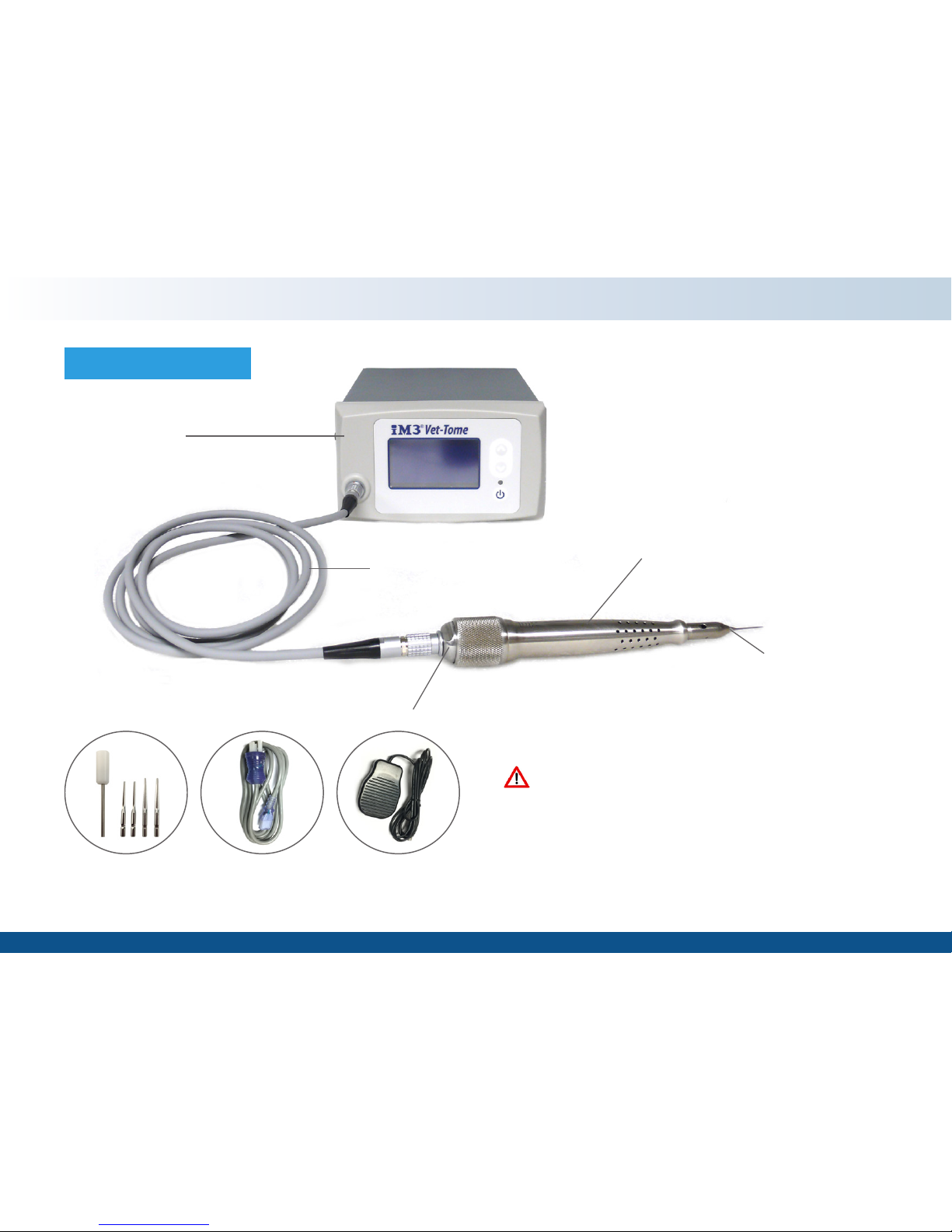
Controller
Handpiece
Tip
Solenoid Assembly
Unpacking
Inspect components and packaging for damage.
If any components have visible defects, including
dents or scratches that have penetrated the labels or
coating, discoloration or moisture damage do not use
the Vet-Tome. Contact iM3 or your local distributor
immediately.
Release Tool
and 4 Tips
Foot
Switch
Power
Cord
PARTS & FEATURES
Handpiece Cable

5
Mains Switch
Foot Switch Connector FUSE Holder
2 x T2A/250V
Replace only with same
type and rating fuse
Display Window
Hand Piece Connector
*indicated by grey ring
Intensity Value & Intensity Icon
Increasing Intensity Switch (1-10)
Decreasing Intensity Switch (1-10)
Hand Piece Standby Switch
Indicator Light
PARTS & FEATURES
5
Table of contents
Other iM3 Medical Equipment manuals


Popular Medical Equipment manuals by other brands


Getinge
Getinge Arjohuntleigh Nimbus 3 Professional Instructions for use

Mettler Electronics
Mettler Electronics Sonicator 730 Maintenance manual

Pressalit Care
Pressalit Care R1100 Mounting instruction

Denas MS
Denas MS DENAS-T operating manual

bort medical
bort medical ActiveColor quick guide

AccuVein
AccuVein AV400 user manual


