Image Diagnostics 1000F Series Product manual

D000-479 REV J MAY-2018 Image Diagnostics, Inc. Page 1
idi
Manufacturer of Quality Medical Products
Image Diagnostics, Inc.
IDI 1000F Series Monitor Suspension System
Model IDI 1000F-1 thru 1000F-6
With Adapter to CAS 8000 Rails
Installation and Maintenance Guide

Installation and Maintenance Guide for IDI 1000F Series Suspension System for use
with CAS 8000 Rails
D000-479 REV J MAY-2018 Image Diagnostics, Inc. Page 2
The text of this manual was originally written, approved and published by the
manufacturer in English.
The information in this manual is subject to change without notice.
CONTENTS
SECTION TITLE
A………………………….. INTRODUCTION, PRODUCT DATA, AND
OPERATION
B………………………….. SYMBOLS
C………………………….. GENERAL SAFETY
D………………………….. SAFETY HAZARDS
E………………………….. INSTALLATION
F………………………….. CLEANING
G………………………….. MAINTENANCE
H………………………….. CUSTOMER SUPPORT
I………………………….. DISPOSAL GUIDELINES
J………………………….. APPROVALS

Installation and Maintenance Guide for IDI 1000F Series Suspension System for use
with CAS 8000 Rails
D000-479 REV J MAY-2018 Image Diagnostics, Inc. Page 3
A. INTRODUCTION
The IDI 1000F Flat Panel Suspension System transports monitors used in
medical imaging procedures. The system features a counterbalanced arm with
vertical travel and internal cable routing. A dual-axis flat panel monitor mount
permits independent panel mounting and positioning. This mobile package
includes clip-mounted ceiling rails.
PRODUCT DATA
Package Includes:
Mobile gantry and counterbalanced swing arm with 42" sweep radius, 25"
vertical travel and +180o rotation
Anodized aluminum ceiling rails with Easymount clip system
Flat panel array with +180o rotation
Array includes display panel mounts with +10o tilt
Complete installation package; meter box mounts, all mounting hardware and
cable management components; brackets, covers and 25' "flexhaust" hose
OPERATION
The monitors are moved along the overhead rails, positioned vertically, and
rotated manually using the handle.
Installation and Maintenance Guide for IDI 1000F Series Suspension System for use
with CAS 8000 Rails
D000-479 REV J MAY-2018 Image Diagnostics, Inc. Page 4
B. SYMBOLS
Attention, consult accompanying documents.
Failure to follow these instructions can cause accidents
resulting in serious injury to patient, user, and damage to
equipment.
Caution, risk of electrical shock
Protective Ground
This is the common tie point between the AC monitor
cord grounds, frame ground, and service (main) ground.
Alternating Current
Weight Limit
Recycle
Some of the materials can be recycled rather than discarded.

Installation and Maintenance Guide for IDI 1000F Series Suspension System for use
with CAS 8000 Rails
D000-479 REV J MAY-2018 Image Diagnostics, Inc. Page 5
C. GENERAL SAFETY
Attention, consult accompanying documents.
Failure to follow these instructions can cause accidents
resulting in serious injury to patient, user, and damage to
equipment.
Only qualified persons may install, operate or maintain this equipment.
Installation of this unit must adhere to applicable codes and authorities having
any jurisdiction over this installation. The customer's architect or engineer is
responsible for assuring that the structural support plans comply with all
applicable codes and regulations.
The unit should be used only in rooms that comply with state, federal and local
recommendations concerning electrical safety when used in medical installations. All
electrical connections shall be done by licensed/approved electrician per national
electric codes.
CAUTION: •Always switch off mains before
performing nonelectrical tests or
maintenance.
•Many positions exist where
equipment or patient collision may
occur. Care must be exercised during
equipment positioning to avoid a
patient or equipment collision.
Changes and additions to the equipment may be performed only by an authorized
representative. These changes must conform to regulations and accepted standards of
good practice. To prevent defeat of the built-in safety mechanisms, changes must be
submitted in writing to the manufacturer for review.
Use only parts specified by Image Diagnostics, Inc. when repairing or servicing this
equipment.
This equipment is intended to only be used with Image Diagnostics, Inc. rails.

Installation and Maintenance Guide for IDI 1000F Series Suspension System for use
with CAS 8000 Rails
D000-479 REV J MAY-2018 Image Diagnostics, Inc. Page 6
D. SAFETY HAZARDS
Installers and Operators using this equipment should understand the safety issues
and operating instructions provided.
Comments and questions regarding safety should be addressed to:
Customer Support
Image Diagnostics, Inc.
310 AUTHORITY DRIVE
FITCHBURG, MA 01420
USA
Or call IDI at (978)829-0009 or send fax to (978)829-0027
Or call IDI Toll Free at (877)304-5434
SAFETY HAZARDS ALERTS
Alert
Circumstances for use
DANGER
Indicates an imminentlyhazardous situation which, if
not avoided, will result in death or serious injury.
WARNING
Indicates a potentially hazardous situation which, if
not avoided, could result in death or serious injury.
CAUTION
Indicates a potentially hazardous situation which, if
not avoided, may result in minor or moderate injury
or equipment damage.

Installation and Maintenance Guide for IDI 1000F Series Suspension System for use
with CAS 8000 Rails
D000-479 REV J MAY-2018 Image Diagnostics, Inc. Page 7
E. INSTALLATION
UNPACK
No special handling is required for unpacking this equipment at the site.
Conventional shipping materials are used.
Recycle or disposal of shipping material per local regulations
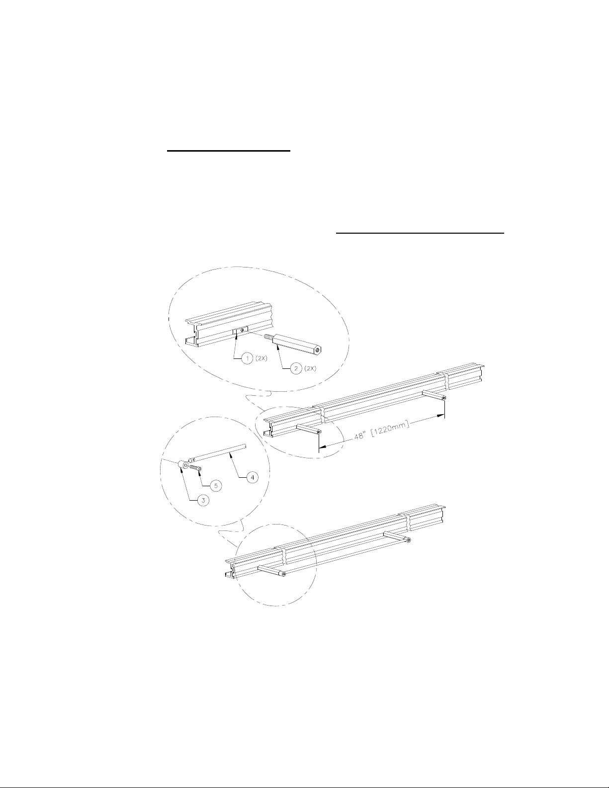
BUILD TRANSVERSE BRIDGE (Refer to Adapter Assembly Drawing)
1. Please note the X/Y ceiling carriage assembly consists of two rail adapter
subassemblies, two unistrut braces and two transverse rails. It is important to
note the two adapters are not identical; the "guide" adapter can be identified by
the thicker wheels and greater wheel offset, (left adapter in drawing below, note
2). The guide adapter will be fitted with a pair of guide wheel bars later on this
assembly.
2. The bridge assembly can be accomplished in position on the longitudinal rails
on the ceiling (recommended) or on the floor and then end loaded into the
longitudinal rails with a Hi-Jack if there is sufficient room between longitudinal
rail ends and any walls or obstructions. To assemble the bridge structure in place
you must first slide each adapter subassemblies onto the left and right
longitudinal rails. If you have sufficient space between the longitudinal rails and
the wall you can simply end load each adapter. If you do not have adequate
space at the end of the longitudinal rails, you may need to remove the center
wheel subassembly so that you can install the adapters by "rolling" them in from
the inside of the "C" section. See figure below.
3. To side load adapters into longitudinal rails, you must loosen (preferably) or
remove the wheel mounts (items 6 & 7) from the rail adapter carriages (item 2)
by removing the mounting hardware (items 21, 22 & 31). If you have removed
the two center wheel mount subassemblies position them on the rails as you
rotate each adapter into place and align the wheel stud and mounting plate to
the adapter. Once the adapters have been loaded into the rails tighten or
reinstall hardware (with LOCTITE #242 or equivalent) while applying
upward pressure on the wheel to maintain contact with the top of the
longitudinal rails.

Installation and Maintenance Guide for IDI 1000F Series Suspension System for use
with CAS 8000 Rails
D000-479 REV J MAY-2018 Image Diagnostics, Inc. Page 8
GUIDE (left view) and STANDARD
RAIL ADAPTER SUBASSEMBLIES
Installation and Maintenance Guide for IDI 1000F Series Suspension System for use
with CAS 8000 Rails
D000-479 REV J MAY-2018 Image Diagnostics, Inc. Page 9
4. Next, mount the two guide bars (item 27) to the guide rail adapter carriage
subassembly using screws (item 33) and locknuts (item 16) as shown below.
Slip white covers (item 36) over the total of eight locknuts associated with the
two guide bars.
MOUNT GUIDE BARS
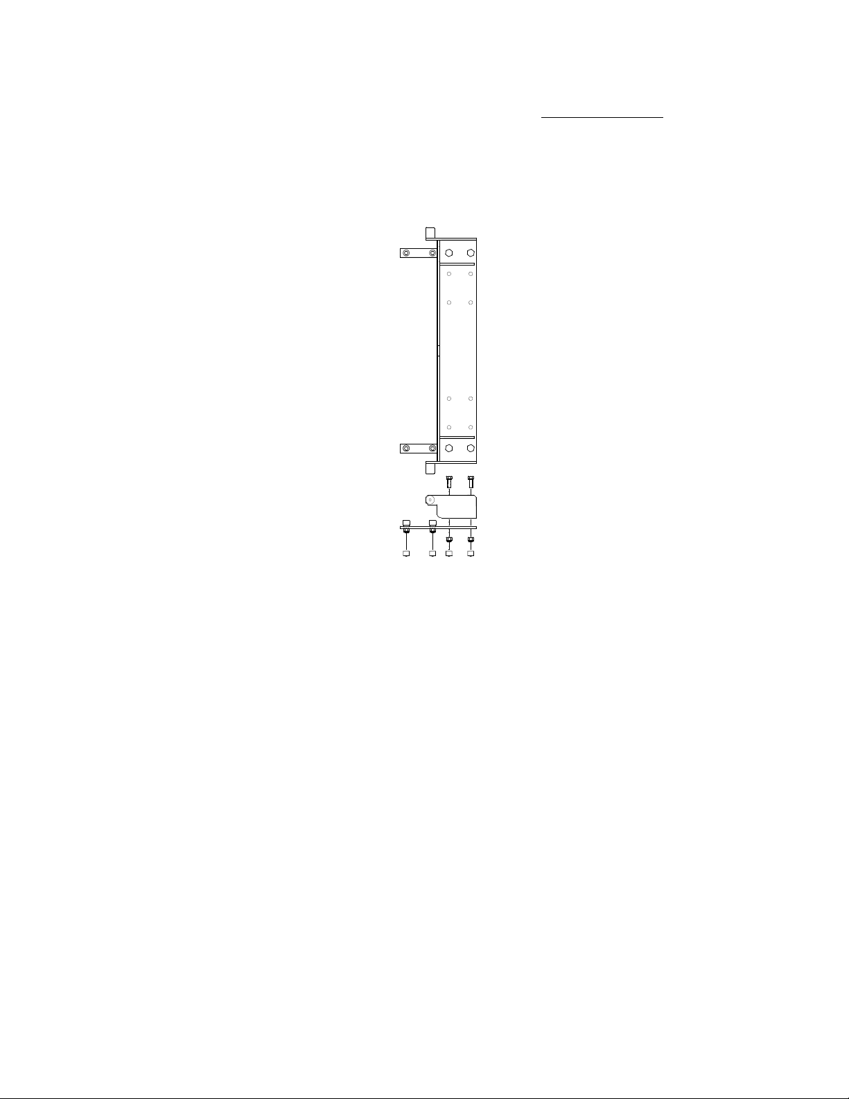
INSTALL BRIDGE STRUTS (Refer to Adapter Assembly Drawing)
1. Attach the two bridge support plates (item 23) to the two bridge struts (item 1)
using flathead screws (item 24) and strut nuts (item 19). Center the plates on the
struts.
2. Attach the two pieces of painted unistrut that make up the bridge (item 1)
between the rail adapter carriage subassemblies using flathead screws (item 24)
and strut nuts (item 19). Use LOCTITE #242 on screws. Snug up hardware to
maintain required dimension and parallelism. Final tightening can be done after
final adjustments.

Installation and Maintenance Guide for IDI 1000F Series Suspension System for use
with CAS 8000 Rails
D000-479 REV J MAY-2018 Image Diagnostics, Inc. Page 10
MOUNT PLATES & STRUTS
3. Check bridge assembly carefully for both parallelism between components and
perpendicularity with the longitudinal rails. Verify the load bearing support
wheels on both sides of the adapter run true and as close as possible to the center
of the longitudinal rails. Once this check is complete tighten all flathead screws
(item 24).
4. Loosely attach rail clips (item 5) to the rail adapter carriage subassemblies (item
2) with hardware (items 14, 26, 15, 16).
5. Remove one outboard rail clip (item 5) from each corner of adapter carriages
and the bridge support plate (item 23). Place one rail (item 9), perpendicular to
the adapter carriages and hold in place. Replace rail clip (item 5), around the
rail flanges. Lightly tighten hardware. Attach the second rail in the same
manner.
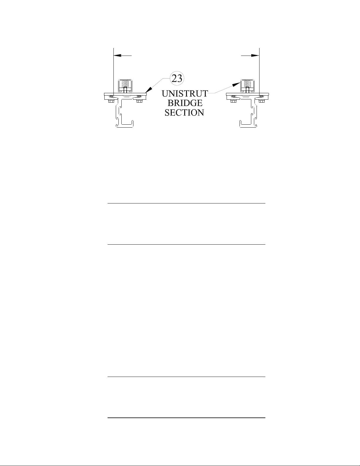
6. Slide the rails back and forth to center them under the adapter carriages and to
align both ends. Make adjustments until the rails are spaced 17 1/8" (43.5cm)
apart at both ends. Tighten clip hardware in 16 places. Reference section view
AA shown in step 2, page 10.
MOUNT PLATES & STRUTS (WIDE CARRIAGE)
A
A
Installation and Maintenance Guide for IDI 1000F Series Suspension System for use
with CAS 8000 Rails
D000-479 REV J MAY-2018 Image Diagnostics, Inc. Page 11
7. Attach clips to middle plates (item 23) installed in step 5 with hardware (item
14, 26, 15, 16). Using LOCTITE #242 and tighten securely.
NOTE: Center wheel (item 10) can be raised or lowered to adjust the space
(lash) between the adapters and the top of the rails. Loosen screws (item 21)
to move mounting plate (item 7) until wheel comes in contact with the surface
on the top of the rail.
WARNING! Failure to properly install this
bridge system and securely attach
all mounting hardware may result
in serious injury to patient, user,
and damage to equipment.
INSTALL RAIL END PLATE (Refer to End Plate Assembly Drawing)
1. Install one end plate (item 22) at the far end of the rails, making sure rubber
bumper (item 23) faces in towards the rails. Use LOCTITE #242 on all threads.
END-LOAD GANTRY (Refer to End Plate Assembly Drawing)
1. Remove shipping straps and packing material from carriage. Using Hi-Jack or
other suitable lift table, raise gantry (still attached to pallet) up and into the
rails. Adjust center wheels if necessary per figure on page 8. Make sure all
carriage wheels are engaged onto rails before lowering Hi-Jack. Remove
pallet and shipping bars from support unit.
WARNING! Remove plastic cover and remove
block of wood between gantry core
and arm. Failure todo so may result
in serious injury to user and damage
to equipment.
17 1/8 inches [43.5cm]

Installation and Maintenance Guide for IDI 1000F Series Suspension System for use
with CAS 8000 Rails
D000-479 REV J MAY-2018 Image Diagnostics, Inc. Page 12
2. Install the second end plate (item 22) at the near end of the rails, making sure
rubber bumper faces in towards the carriage. Use LOCTITE #242 on all
threads.
WARNING! Failure to install both rail end plates
may result in serious injury to user.
INSTALL MONITOR MOUNT (Refer to Monitor Mount Assembly Drawing)
NOTE TO INSTALLER: It is important that the load be balanced on the
monitor mount. Take into account any differences in size and weight of the
monitors.
1. Remove wireway cover (item 38).
2. Drop rotation bearing (item 50) into pivot plate (item 59).
3. Take the thicker thrust ring (item 20) and put around rotation bearing (item 50).
4. Place stainless-steel thrust ring (item 47) below the thicker thrust ring (item 20).
5. The six bolts (item 16) with lockwashers (item 29) go through rotation cap (item
43) and rotation bearing (item 50) into the pivot tube (item 43 in the Core
Assembly Drawing). Use LOCTITE #242 on hardware.

Installation and Maintenance Guide for IDI 1000F Series Suspension System for use
with CAS 8000 Rails
D000-479 REV J MAY-2018 Image Diagnostics, Inc. Page 13
6. Apply a very little amount of LOCTITE #242 to and insert the six setscrews
(item 24) into the six threaded holes on second rotation cap (item 43). Thread
the setscrews in until they contact the rotation cap (item 43). The setscrews
may be tightened or loosened later to adjust rotational resistance.
WARNING! Failure to securely attach hardware
may result in serious injury to
patient, user, and damage to
equipment.
INSTALL MONITOR (Refer to Monitor Mount Assembly Drawing)
Maximum weight of any individual monitor.
Maximum total weight of monitors.
1. To attach a monitor to the system, first remove a monitor mounting bracket
(item #30) by removing its mounting screw (item #21). Fasten the bracket to
the monitor (hardware not provided). Reinstall the bracket with the monitor.
WARNING! Failure to securely attach hardware
may result in serious injury to
patient, user, and damage to
equipment.
2. Monitors can be tilted and rotated.
3. If monitor tilt resistance is inadequate and it fails to stay in the desired position,
tighten bolt (item 21).
4. If monitor rotation resistance is inadequate and it fails to stay in the desired
position, tighten bolt (item 22).
NOTE TO INSTALLER: Ground stud (item 27) has been provided to
properly ground monitors as a group. Terminal strip (item 31) has been
provided for distribution of line voltage to each monitor. Cut and strip each
monitor power cord to fit.
25 LBS
11 kg
44 kg
96 LBS

Installation and Maintenance Guide for IDI 1000F Series Suspension System for use
with CAS 8000 Rails
D000-479 REV J MAY-2018 Image Diagnostics, Inc. Page 14
SET ROTATIONAL LIMITS (Refer to Monitor Mount Assembly Drawing)
1. If desired, the stop pin (item 4) can be relocated to another of its four possible
mounting locations. Remove rotational cover (item 35) to access the stop pin
mounting screw (item 52).
ELECTRICAL CONNECTIONS
1. Colors of conductors in power supply cords shall be in accordance with IEC
publication 60227 (amendment #1) or with IEC publication 60245.
Wiring Color Codes:
International: brown (line), blue (neutral), green/yellow (ground)
North America: black (line), white (neutral), green/yellow (ground)
2. Cable tie mounting platforms are supplied near the terminal block for anchoring
the monitor cords and the wires from the mains. Use nylon cable ties. (Tying
the cord into a knot or tying the ends with string shall not be used for cord
anchorage).
3. Conductors of the power supply cord shall be arranged that the protective earth
conductor is not subject to strain as long as the phase conductors are in contact
with their terminals.
4. All power cords used for mains connection shall have double insulation.
Conduit provided for routing cables shall not be relied on for insulation.
FOUR POSSIBLE
STOP PIN
MOUNTING POSITIONS
Installation and Maintenance Guide for IDI 1000F Series Suspension System for use
with CAS 8000 Rails
D000-479 REV J MAY-2018 Image Diagnostics, Inc. Page 15
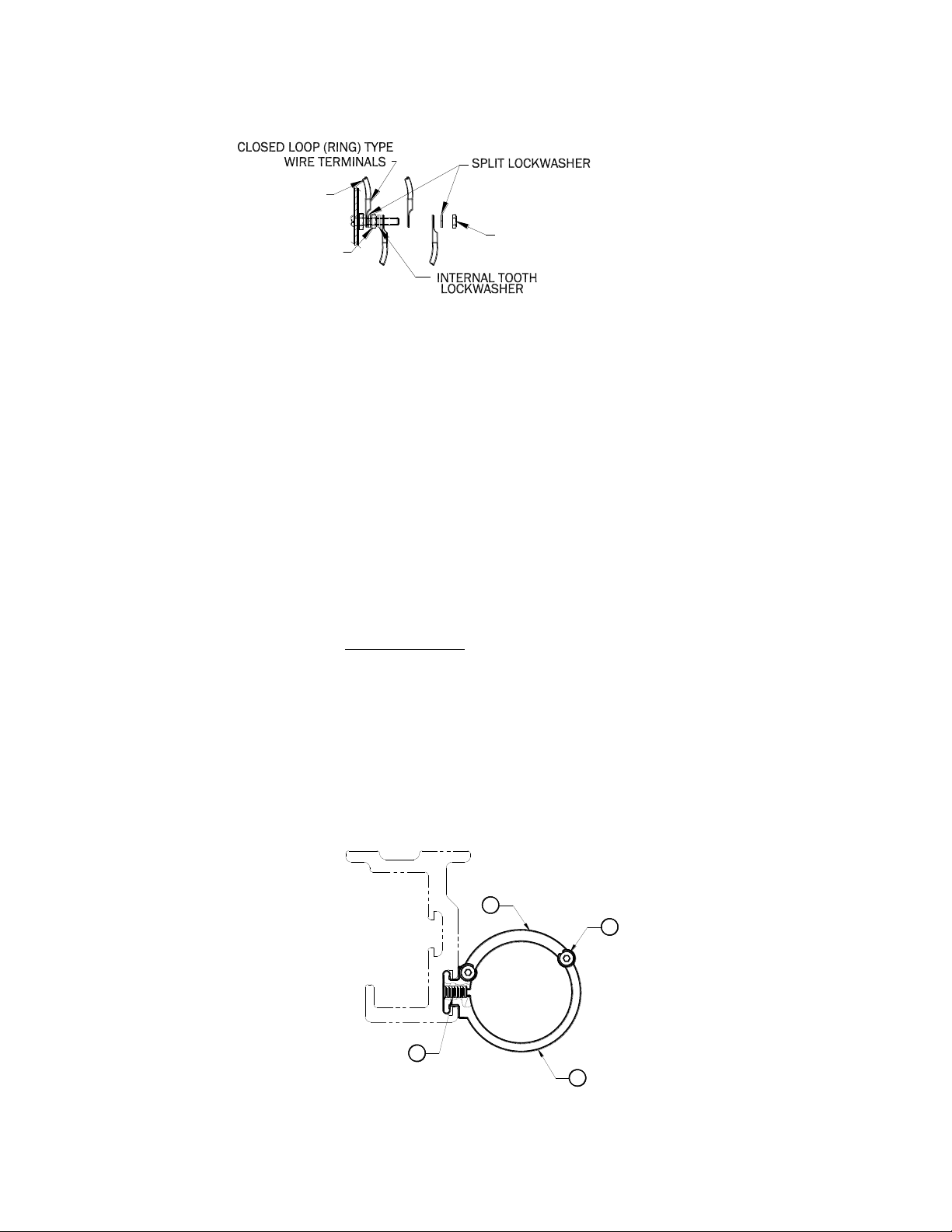
5. Connect all monitor ground wires and the service ground wire as shown in the
figure above. (The number of wires varies with the number of monitors
installed).
INSTALL STATIONARY CABLE HANDLING ASSEMBLY
(Refer to Stationary Cable Handling Kit Drawing)
1. Determine which rail end the stationary cable handling kit will be positioned.
If, at the far end of the rail, slide kit into rail track; slide kit into rail track
prior to positioning the mobile cable handling kit. If stationary kit is to be
positioned at the near end of rail, slide into rail after positioning mobile cable
handling kit. Stationary kit is typically mounted approximately 6 inches
(15cm) from rail end.
2. After applying LOCTITE #242 to threads, tighten the setscrew (item 4) to
secure in place.
3. Remove retainer (item 2) by taking out the two mounting screws (item 3).
4. Place section of cable hose into clamp (item 1).
5. Reinstall retainer (item 2) screws (item 3).
4
2
1
2X3
(#10-32 HARDWARE)
NUT "B"
MAIN GROUND WIRE
FROM SERVICE
NUT "A"
under split lockwasher and nut "A".
First attach main ground wire
Attach all other ground wires
between nut "A", lockwashers,
and nut "B".
Installation and Maintenance Guide for IDI 1000F Series Suspension System for use
with CAS 8000 Rails
D000-479 REV J MAY-2018 Image Diagnostics, Inc. Page 16
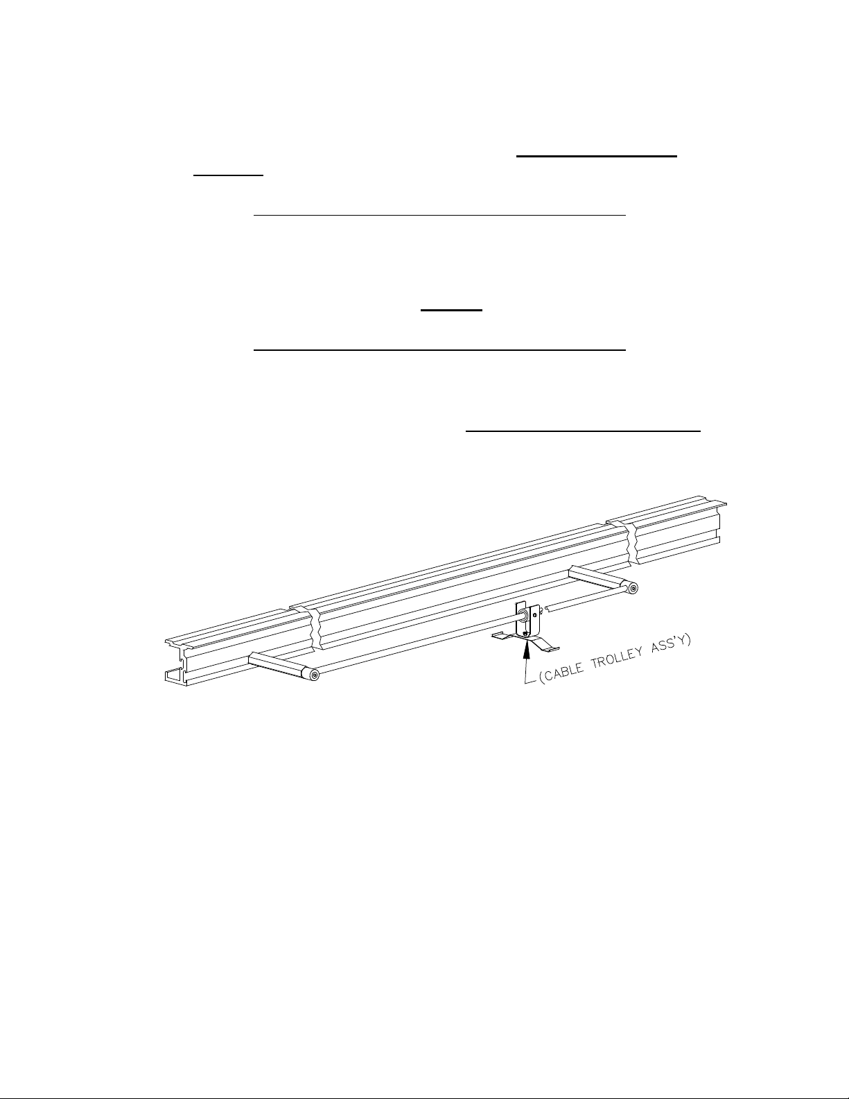
INSTALL MOBILE CABLE HANDLING ASSEMBLY (Refer to Cable Handling
Kit Assembly Drawing)
1. Slide nut plate of two hanger standoff assemblies (items 1&2) into rail track.
After applying LOCTITE #242 to the end that will be secured into the nutplate
(item 1), position standoffs approximately 48" (122cm) from each other. To
assure proper fit and positioning, temporarily assemble cable hanger shaft
(item 4) to standoffs. Place one shaft support (item 3) onto far end standoff.
Place the other shaft support to the second standoff, while temporarily
installing cable hanger shaft (item 4) into holes of shaft supports. Lightly
tighten socket head cap screws (item 5). Use LOCTITE #242 on hardware.
Installation and Maintenance Guide for IDI 1000F Series Suspension System for use
with CAS 8000 Rails
D000-479 REV J MAY-2018 Image Diagnostics, Inc. Page 17
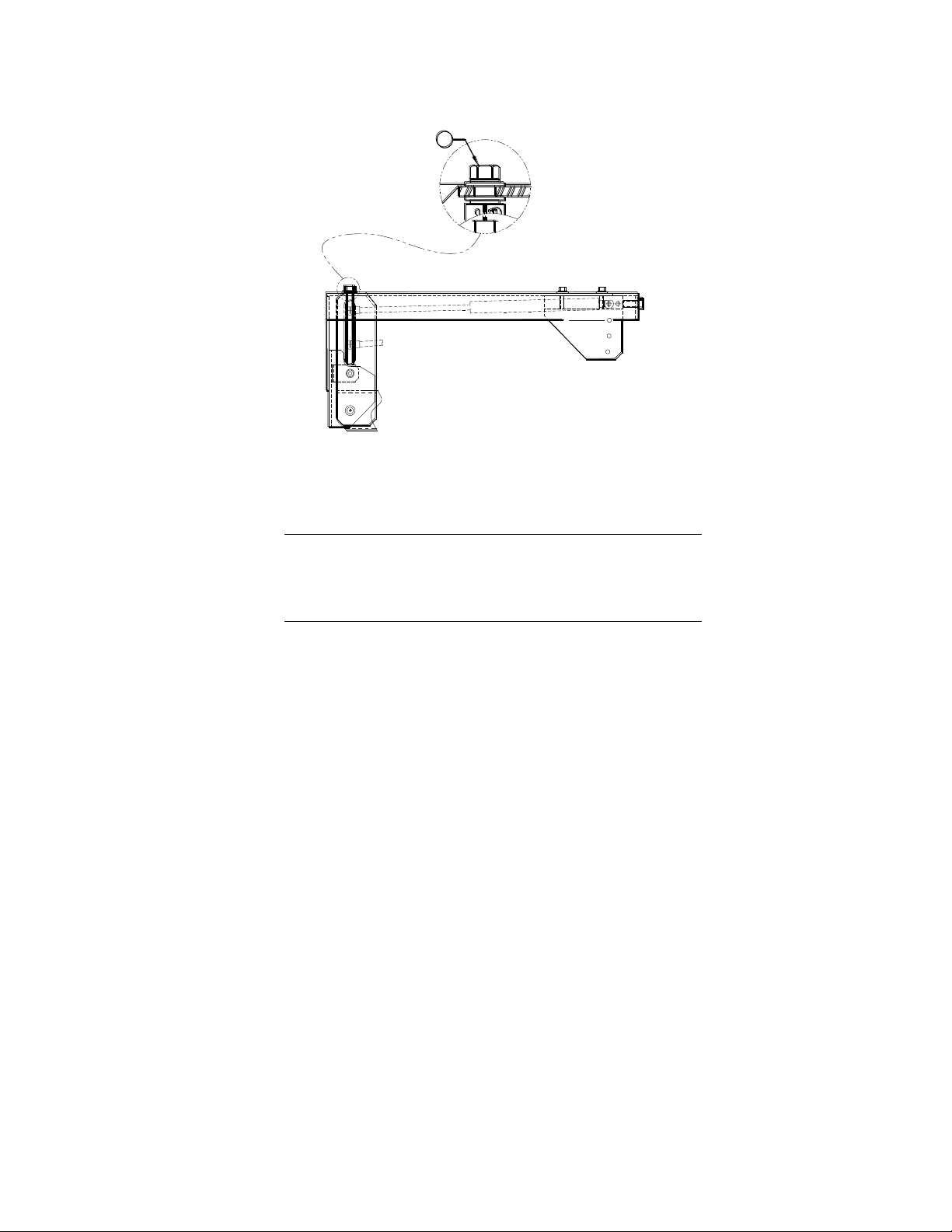
2. Position shaft/cable handling subassemblies (items 1-5) to desired location on
rail. Without disrupting alignment, remove shaft and shaft supports. Torque
standoffs to ~35-50 inch pounds, 4.2-6.0(Nm). Use LOCTITE #242 on
hardware.
CAUTION! Over tightening the standoff will
weaken or break the set screw
connecting the standoff to the nut
plate causing attached components
to fall. DO NOT loosen or adjust the
exposed length of the setscrew on the
standoff.
3. Reattach shaft supports. Install one end of shaft to a shaft support. Tighten
socket head cap screw (item 5). Slide cable trolley assembly(s) onto cable
hanger shaft (item 4). Install free end of shaft into other shaft support. Tighten
second socket head cap screw (item 4). Use LOCTITE #242 on hardware.
DRESS CABLES (Refer to Gantry Core Assembly)
1. When the monitors have been properly installed, it is recommended that the
cables be brought through the pivot tube (item 43). 2" (5cm) flexaust (provided)
is to be attached to pivot tube and to be routed underneath the arm (item 51) via
the cable clamps (items 46, 50). Rotate entire system and bring to maximum
positions: the system should not drift from any position. If it does, check that
enough cable has been left to allow freedom of motion.

Installation and Maintenance Guide for IDI 1000F Series Suspension System for use
with CAS 8000 Rails
D000-479 REV J MAY-2018 Image Diagnostics, Inc. Page 18
36" [914mm]
HANDLING ASSEMBLY
MOBILE CABLE
48" [1220mm]
BETWEEN COMPONENTS
APPROX. LENGTH OF CABLE HOSE
*
[400mm]
15 3/4"
47" [1200mm]
*
LOCATIONS MAY REQUIRE SOME VARIATION
ACTUAL ROOM LAYOUT AND EQUIPMENT
CONFIGURATION
OPTIMUM CABLE HOSE
HANDLING ASSEMBLY
STATIONARY CABLE
*
BALANCE SYSTEM (Refer to Gantry Core Assembly)
Note: System balance has been set at factory based upon quoted monitor weight.
1. Note initial settings from Spring Data label (item 18). Substantial increases in
payload may require spring change.
2. Prior to adjustment - payload must be secure and arm horizontal. Fine
adjustment to compensate monitor counterbalance can be made by turning
adjustment screw (item 53). Rotate adjustment nut:
clockwise to increase capacity
counter clockwise to decrease capacity
Installation and Maintenance Guide for IDI 1000F Series Suspension System for use
with CAS 8000 Rails
D000-479 REV J MAY-2018 Image Diagnostics, Inc. Page 19
53
Yoke Balance Adjustment
WARNING! Yoke has been leveled at
manufacturers. Make adjustment
only if absolutely necessary to
compensate for an unbalanced load.
NOTE: Prior to yoke adjustment - payload must be secure and arm horizontal.
1. Fine adjustment, to compensate for yoke balance, can be made by turning the
link (item 48). Loosen threaded hex nut (item 24) at outboard rod end (item 10);
spin link until yoke is in a horizontal position; retighten hex nut.
MONITOR MOUNT ASSEMBLY ROTATION RESISTANCE
1. The setscrews (item 24) installed in step 6 of "INSTALL MONITOR MOUNT"
on page 12 can be loosened or tightened to adjust the rotation resistance of the
suspended monitor mount assembly.
2. Replace wireway cover (item 38) after making adjustment.

Installation and Maintenance Guide for IDI 1000F Series Suspension System for use
with CAS 8000 Rails
D000-479 REV J MAY-2018 Image Diagnostics, Inc. Page 20
F. CLEANING THE EQUIPMENT
No part of this unit is designed to be sterilized in an autoclave. Do not allow
water or other liquids to enter the equipment as this may cause short circuits or
corrosion. Clean parts with a clean cloth dampened with disinfectant or a mild
detergent solution. Do not use abrasives, solvents, sprays or corrosive cleaning
agents. Gently rub with a clean soft cloth to dry.
If room is to be disinfected by means of an atomizer, the equipment must be
covered with plastic or similar sheeting. The equipment must be turned off well
in advance of this procedure to prevent convection currents from drawing the
disinfectant mist into the equipment. After the mist disperses completely, the
sheeting may be removed and the equipment disinfected as described above.
G. MAINTENANCE
"Authorized Technician"
All maintenance procedures should be done by an experienced technician with
demonstrated knowledge and skills (electrical and mechanical) relative to this
type of equipment.
This individual must have access to this manual and the proper tools.
Daily Maintenance Checks:
1. Pre-Operational and Post-Operational Checks
Perform daily checks of the monitor suspension BEFORE and
AFTER operating the equipment.
CAUTION! If any abnormality is found in the
monitor suspension, stop using it. Post
a sign reading "DO NOT USE" so that
the system is not used by mistake.
2. Visual check
Before checking the operation, confirm the following:
•The monitor suspension is not tilted. Refer to the following figures.
•Although "A" in the following figure shows a gap, there is no gap at the
monitor frame rotation section.
•Monitors installed on the monitor suspension are not tilted.
This manual suits for next models
6
Table of contents
Other Image Diagnostics Protection Device manuals


