IMAGENEX TECHNOLOGY CORP. 852-000-145 User manual

IMAGENEX TECHNOLOGY CORP.
MODEL 852-000-145
ULTRA-MINIATURE DIGITAL
ECHO SOUNDER
ECHO SOUNDER S/N _____________
IS CONFIGURED FOR:
_______________ VDC INPUT
______________ @ 115.2 kbps
IMAGENEX TECHNOLOGY CORP.
209-1875 BROADWAY STREET
PORT COQUITLAM, B.C.
CANADA, V3C 4Z1
TEL: (604) 944-8248
FAX: (604) 944-8249

852 Echo Sounder 11000 m
445-060 MARCH 2009-REVISED MAY 2017
Specifications subject to
IMAGENEX MODEL 852
ULTRA-MINIATURE 11000 m ECHO SOUNDER
APPLICATIONS: FEATURES:
•ROV Navigation •Ultra-miniature size is ideal for mounting
•Diving Support on today’s micro ROV’s
•Inspection •Low cost
•Search & Recovery •Direct connection to laptop computer
•External trigger available
The Model 852 Digital Echo Sounder was
designed for use with the smallest of ROV’s.
For maximum flexibility, the unit requires
approximately 1.5 Watts from 24 VDC, or
optional 48 VDC. Serial communication is
utilized, RS-485 or RS-232 at 115.2 kbps.
The maximum operating range is 50 meters.
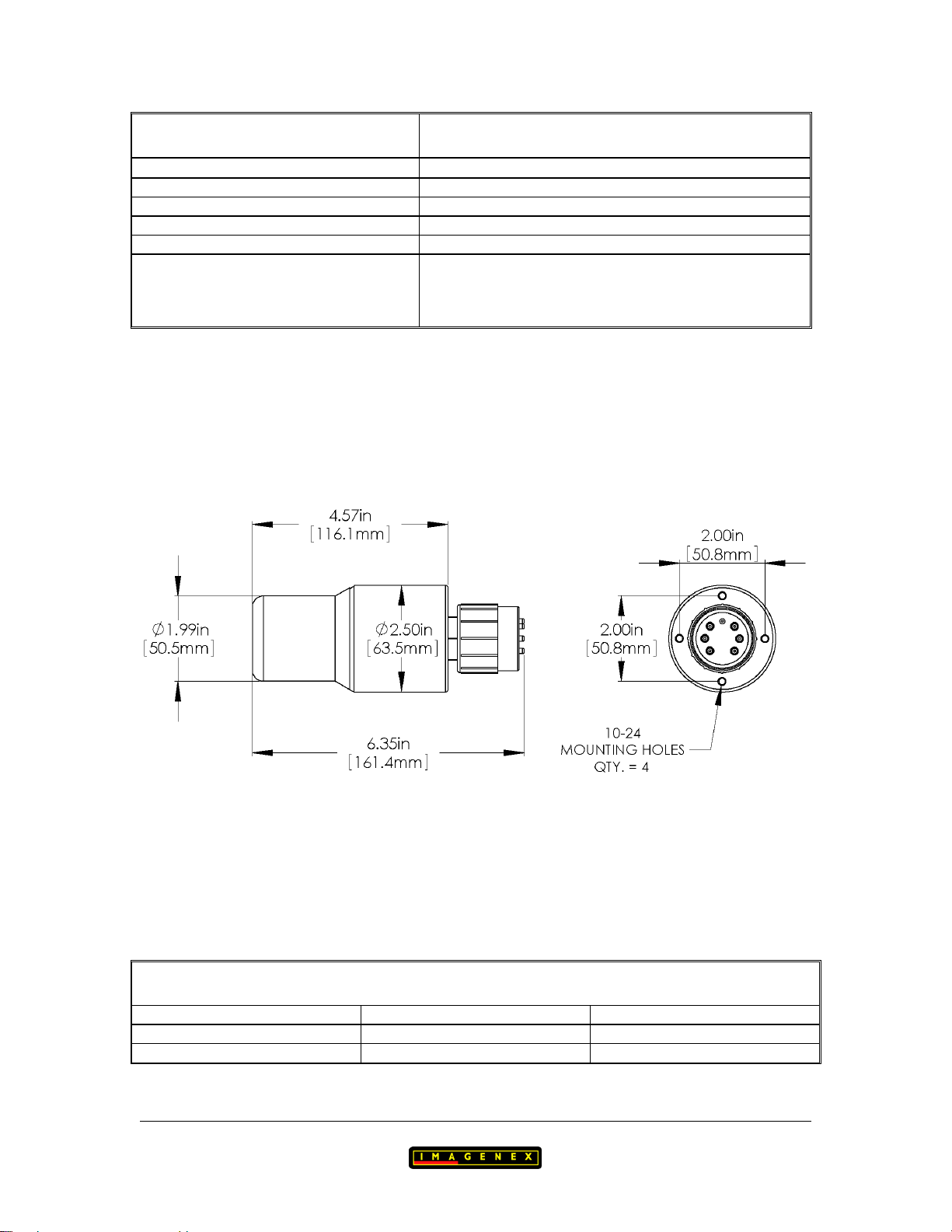
HARDWARE
SPECIFICATIONS:
FREQUENCY 330 kHz
TRANSDUCER BEAM WIDTH 30°Conical
RANGE RESOLUTION 20 mm
MIN. DETECTABLE RANGE 500 mm
MAX. OPERATING DEPTH 11000 m
MAX. CABLE LENGTH 1000 m on typical twisted shielded pair
INTERFACE RS-485 @ 115.2 kbps (RS-232 optional)
CONNECTOR BH6M-Titanium
POWER SUPPLY 22 – 30 VDC at less than 1.5 Watts
Optional 40 – 56 VDC
DIMENSIONS See drawing
WEIGHT: In Air
In Water
~913 g (~2 lbs)
~0.75 kg (~1.7 lbs)
MATERIALS 6AL4V Titanium, PVC, Epoxy
FINISH Natural
Copyright ©2009 - 2019
change without notice www.imagenex.com Imagenex Technology Corp.
SOFTWARE
SPECIFICATIONS: Win852.exe
WINDOWS™OPERATING SYSTEM Windows™XP, Vista, 7, 8, 10
MODES Echosounder
RANGE SCALES 5 m, 10 m, 20 m, 30 m, 40 m, 50 m
EXTERNAL INPUT Depth, Heading, Turns
FILE FORMAT (filename).852
RECOMMENDED
MINIMUM COMPUTER
REQUIREMENTS:
100 MHz Pentium
16 MB RAM
1 GB Hard Disk
800 x 600 x 256 colour graphics
ORDERING
INFORMATION:
11000 m UNIT Standard 852-000-145
RS-232 Option -006
40 – 56 VDC Option -013
Product and company names listed are trademarks or trade names of their respective companies.
852 Echo Sounder 11000 m 2
445-060 www.imagenex.com


Page 1 of 10
IMAGENEX TECHNOLOGY CORP. 18FEB16
MODEL 852 ULTRA-MINIATURE DIGITAL
SCANNING SONAR HEAD
and ECHO SOUNDER
WIN852.EXE: Display Software For Windows XP/Vista/7/8/10
VERSION 2.09
OVERVIEW
WIN852 is a Windows program that controls, displays and records data from the Model
852 Ultra-Miniature Digital Scanning Sonar Head and/or the Model 852 Ultra-Miniature
Digital Echo Sounder. The program uses a 2-Wire RS-485 COM port (115200,N,8,1) to
communicate with the heads and an RS-232 COM port (38400,N,8,1) for receiving
Remotely Operated Vehicle (ROV) information such as Depth, Heading and Turns
Count. The heads can be operated at different ranges, gains, pulse lengths, etc. The
Windows display mode must be at least 800 x 600 pixels with a small font.
SCREEN LAYOUT
The main screen of WIN852 comprises of a sonar data window on the left side with
various sonar head controls and a sector size icon on the right side. The echo sounder
window overlays the sonar window and is expandable. Other items include a x2 Pixel
Zoom window, date/time readout, Depth/Heading/Turns readout, sonar head
range/bearing readout to one or two cursors and a control for displaying real time data
from the heads or playback data from a file. A pop-up window is available for displaying
diagnostics. A compass rose can be displayed in place of the pixel zoom window.
OPERATION
To operate the sonar head and echo sounder, ensure that the head cable is connected to
the 2-Wire RS-485 serial port or an RS-485 to RS-232 converter is installed in-line.
Connect 22 to 30VDC to the power wires (+V to RED, -V to BLACK) using a DC power
supply capable of supplying a current of 1 Amp. Run the program WIN852.EXE and
select the button DATA FROM 'HEAD' on the right-hand side of the display. Ensure that
the correct COM port is selected (Com Ports Menu) and depending on the RS-485 serial
i/o card installed in your computer, select AUTO Enable or RTS (Request To Send)
Enable. Also ensure that the sonar head and/or echo sounder is enabled via the Set
Switches Dialog Box. To allow other programs to use available CPU time, WIN852 can
be put into standby mode simply by minimizing the main window.

Page 2 of 10
MAIN MENU
File Menu
Record Start (Stop)... opens a File Name Dialog Box so the user can input a
filename for logging sonar and/or echo sounder data (shot
by shot) complete with date/time stamp. The file
extension is always '.852'. The filename and current size
(kbytes) of the file are displayed at the top of the screen.
File recording continues until Record Stop is selected.
Available only when DATA FROM 'HEAD' is active.
Playback... opens a File Name Dialog Box so the user can select and
playback a previously recorded '.852' Sonar file. Available
only when DATA FROM 'FILE' is active.
Copy Start (Stop)... opens a File Name Dialog Box so the user can enter a
filename for a new ‘.852’ file that can be used for making
smaller data files from large pre-recorded sonar files. The
filename and current size (kbytes) of the file are displayed
at the top of the screen. File copying continues until Copy
Stop is selected. Available when DATA FROM 'FILE' is
active.
Save Screen... opens a File Name Dialog Box so the user can enter a
filename for saving the screen as a '.BMP'bitmap file.
Exit writes current configuration to file (WIN852.INI), closes
the program and exits to Windows.
Color Table Menu
Norm Hi normal high intensity color table used for mapping the
echo data amplitude to a color for display. Color depth is
107 colors ranging from Black (low level) through Blue,
Green, Orange, Yellow, White and Red (max level).
Norm Lo normal low intensity color table.
Green 107 shades of green.
Grey 107 shades of grey (White on Black).
Rev Grey 107 shades of grey (Black on White).
Brown/Yellow 107 mixed shades of brown and yellow.
Green/Blue 107 mixed shades of green and blue.
Green/Yellow 107 mixed shades of green and yellow.
Blue 107 shades of blue.

Page 3 of 10
MAIN MENU (con't)
Options Menu
Units to change the units of measurement from Meters to Feet.
Xdcr Position to adjust the display of the sonar head echo data relative to
the physical mounting of the sonar head. If the xdcr
(transducer) is physically mounted down (red side down),
this switch should be set to 'Down'. If the xdcr is mounted
up (red side up), 'Up' should be selected. If this switch is
set incorrectly, the sonar display will appear as a mirror
image; targets which are actually on the right side will
appear on the left, and vice-versa.
Noise Filter to minimize noise in the displayed return data.
Sound Velocity to change the speed of sound number used in range
measurements. This number can have a range of 750 m/s
(2461 ft/s) to 2250 m/s (7381 ft/s). The default is 1500
m/s (4921.3 ft/s).
User Text to enter a text string for display in the User Text Window.
Calibrate Sonar Head to adjust the motor to the center or zero position.
Com Ports Menu
Sonar Head to select the serial communications port (COM1-COM32)
for communicating with the connected sonar head and/or
echo sounder. Ports that are already used or unavailable
are greyed out. The port that is selected must be a 2-Wire
RS-485 serial port. Alternatively, you could use an RS-
232 port with an external RS-485 to RS-232 converter
connected in-line. All communication through this port is
at 115200 bits per second, No Parity, 8 Data Bits and 1
Stop Bit.
AUTO Enable use this mode if your RS-485 serial i/o card or converter
can automatically enable its’ transmit driver. Two
excellent converters are the SeaLink +485I (P/N 2104)
from www.sealevel.com and the Model 9365 from
www.telebyteusa.com which automatically enable the
transmit driver when sending data as opposed to
controlling the driver via RTS (Request To Send).

Page 4 of 10
MAIN MENU (con't)
RTS Enable use this mode if your RS-485 serial i/o card or converter
requires RTS (Request To Send) to enable its’ transmit
driver.
Depth/Heading/Turns to select the serial communications port (COM1-COM32)
for receiving Depth, Heading and Turns Count
information generated from an ROV computer system.
This port accepts the following comma deliminated ASCII
serial string at 38400,N,8,1:
dddd.d,F,hhh.h,-tt<CR><LF>
dddd.d is the ROV depth (0000.0 to 9999.9)
Ffor depth in Feet or Mfor depth in Meters
hhh.h is the ROV compass heading in degrees (000.0 to
359.9)
–tt is the ROV turns counter (-99 to 99). Negative
numbers contain a leading minus sign, positive numbers
contain a leading space character (no plus sign).
<CR> - carriage return
<LF> - line feed
If the program detects only one available COM port (i.e.
on a laptop computer), this port will be reserved for
communications with the sonar head only and the
Depth/Heading/Turns input will not be available.
As default on older computers, COM1/COM3 share IRQ4
(interrupt request #4) and COM2/COM4 share IRQ3.
Ensure that the COM port you select for the
Depth/Heading/Turns input does not share its IRQ with
the sonar head COM port. This could cause the program
to hang up!
Enable/Disable use this selection to enable or disable the
Depth/Heading/Turns serial port input.

Page 5 of 10
MAIN MENU (con't)
Set Switches Menu
Sonar Head
Enable / Disable to enable or disable sonar head communications.
The following parameters can be controlled:
Range 5, 10, 20, 30, 40, 50 Meters or equivalent Feet
Gain 0 to 40 dB
Train Angle not available
Sector Size 0 to 360 degree in 3 degree increments
Speed Normal (3 degrees/step), Fast (6 degrees/step)
Pulse Length 10 to 250 microseconds in 10 microsecond increments
Switch Delay 0 to 500 milliseconds in 2 millisecond increments
Frequency 675kHz or 850 kHz
Echo Sounder
Enable / Disable to enable or disable echo sounder communications.
Enabling the echo sounder will display the Echo Sounder
data window.
The following parameters can be controlled:
Range 5, 10, 20, 30, 40, 50 Meters or equivalent Feet
Gain 0 to 40 dB
Pulse Length 10 to 250 microseconds in 10 microsecond increments
Profile Off, Points, Low-Mix, Med-Mix or High-Mix
Profile Min. Range 0 to 25 Meters in 0.1 Meter increments
Switch Delay 0 to 500 milliseconds in 2 millisecond increments
Frequency 675kHz only
Select the Default button to quickly return to factory default settings.

Page 6 of 10
MAIN MENU (con't)
Misc Menu
Grid On/Off to display the range rings on the sonar display.
Pixel Zoom (x2) displays a x2 pixel zoom window in the lower right
hand corner of the screen. A rectangular area about
the cursor is displayed in this window. If the left
mouse button is pressed anywhere in the sonar
image window, the zoom window will be captured
(held). Pressing the button a second time releases
the capture.
Compass Rose displays a circular compass rose in place of the
pixel zoom window (if Depth/Heading/Turns is
enabled).
Clear Screen Now to clear all echo data from the sonar display.
Diagnostics displays the Diagnostics Pop-Up Window. This
window displays the header information from the
sonar head.
ES Profile Mode Off, Points Only, Low Mix, Med Mix, High Mix
ES External Trigger Enable to enable or disable the Echo Sounder External
Trigger function
ES External Trigger Edge select Positive or Negative trigger edge
ES External Trigger Mode select Manual or Automatic Trigger function
Sonar External Trigger Enable to enable or disable the Sonar Head External
Trigger function
Sonar External Trigger Edge select Positive or Negative trigger edge
Sonar External Trigger Mode select Manual or Automatic Trigger function

Page 7 of 10
MAIN MENU (con't)
Sonar On When Minimized when this item is checked, the sonar head and/or
echo sounder will continue to operate and log data
when the sonar screen is minimized. If not checked,
the serial port is closed while communication and
data logging are put on hold until the screen is
maximized. This allows other programs to use the
serial port and available CPU time
Help Menu
About... displays an about box showing the software version and
date of this program.

Page 8 of 10
ON SCREEN SWITCHES
DATA FROM 'HEAD' to display data from the connected sonar head and/or echo
sounder
DATA FROM 'FILE' to display data from a previously recorded '.852' Sonar
file.
Hold to hold or freeze the display.
Rev to reverse the current scanning direction of the sonar head.
Available only when DATA FROM 'HEAD' is active.
TrackBar to re-position the file pointer during file playback.
Available only when DATA FROM 'FILE' is active.
Plot Speed to adjust plotting speed during file playback.
Available only when DATA FROM 'FILE' is active.
The following switches are available only when DATA FROM 'HEAD' is active:
Range to change the sonar operating range. Ranges available are:
5m (15ft), 10m (30ft), 20m (60ft), 30m (90ft),
40m (120ft) and 50m (150ft)
Mode to change the sonar display mode. Modes available are:
Sector, Polar and Sidescan.
Start Gain to change the starting gain of the sonar head. Increase to
get higher return levels, decrease to get lower return
levels. The Start Gain can be adjusted from 0dB to 40dB
in 1dB increments.
Speed to change the stepping speed of the sonar. Speeds
available are:
Normal (3 deg/step) and Fast (6 deg/step)
Sector to change the sector size (sweep angle).
Sector Mode (0 to 180 degrees in 18 degree increments)
Polar Mode (0 to 360 degrees in 18 degree increments)
Two hot swap buttons are available for changing the
sector size from 90 to 180 degrees in Sector Mode or from
90 to 360 degrees in Polar Mode.

Page 9 of 10
ON SCREEN SWITCHES (con’t)
Train always 0 degrees in Sector and Polar Modes.
Up, Down, Port and Stbd settings are available for
Sidescan Mode.
KEYBOARD SWITCHES
The following switches are selected via keyboard entry (case insensitive):
C to clear the sonar screen display.
G to change the Start Gain of the sonar head. When the 'G'
key is pressed, the Key Command Entry Box displays the
prompt: Gain: ? dB. Type in a valid start gain number (0-
40dB) and press <Enter> to change to the new start gain
value. If the entered gain is not valid or the <Esc> key is
pressed, the current gain will be used. Available only
when DATA FROM 'HEAD' is active.
H to hold or freeze the display.
R to change the operating range of the sonar head. When the
'R' key is pressed, the Key Command Entry Box (below
the DATA FROM buttons) is displayed with the
following prompt: Range: ? M (meters) or Range: ? FT
(feet). Type in a valid range number: 5(15), 10(30),
20(60), 30(90), 40(120) or 50(150) in meters or (feet)
using the numeric keys and then press <Enter> to change
to the new range. If the entered range is not valid or the
<Esc> key is pressed, the current range will be used.
Available only when DATA FROM 'HEAD' is active.
Space Bar to reverse the current sonar head scanning direction. Can
also be used to reverse the file playback direction.

Page 10 of 10
ONE CURSOR MEASUREMENT
One Cursor Measurement is used for measuring the distance and relative bearing to a
target with respect to the transducer origin. When the mouse is moved into the sonar
image display area, the cursor changes from an arrow to a square target cursor. The range
and bearing to the target cursor is displayed in the Range/Bearing Display Box
underneath the sonar image display. If a compass heading is present at the second serial
port, the displayed cursor bearing will include the copmpass heading. The area about the
target cursor is also displayed in the Pixel Zoom window. Clicking the left mouse button
while the cursor is in the sonar image display area captures (freezes) the zoom window
image. Clicking the left button a second time allows normal zoom window updating.
TWO CURSOR MEASUREMENT
Two Cursor Measurement is used for measuring the distance and relative bearing
between two targets. To invoke two cursor measurement, position the mouse cursor over
a target in the sonar image display area and press the right mouse button. A target origin
cursor is placed at this location. When the mouse is moved, a rubber banded line is drawn
from the target origin cursor to the target cursor. The Range/Bearing Display Box shows
the range and bearing from the transducer origin to the target cursor (Tar) and the range
and bearing difference (Diff) between the two cursors. If a compass heading is present at
the second serial port, the displayed cursor bearing will include the copmpass heading.
The displayed range and bearing between the two cursors is always relative to the target
origin cursor. Press the right mouse button again to return to One Cursor Measurement.
MESSAGES
No Data at COM? - no power to the sonar head and/or echo sounder
- cable not connected
- Sonar Head COM port set to the wrong port number
- computer not fast enough to keep up with the head
increase Switch Delay.
Depth ‘n/a’
Heading ‘n/a’
Turns Counter ‘n/a’ - ROV computer not connected to serial port
- ROV computer is not sending data
- ROV computer not set for 38400,N,8,1
- Depth/Heading/Turns COM port set to the wrong
port number
- ROV computer not sending correct ASCII string
Page 1 of 5
IMAGENEX TECHNOLOGY CORP. 16SEP15
MODEL 852 DIGITAL SONAR HEAD
MODEL 852 DIGITAL ECHO SOUNDER
DATA STORAGE FILE FORMAT (.852)
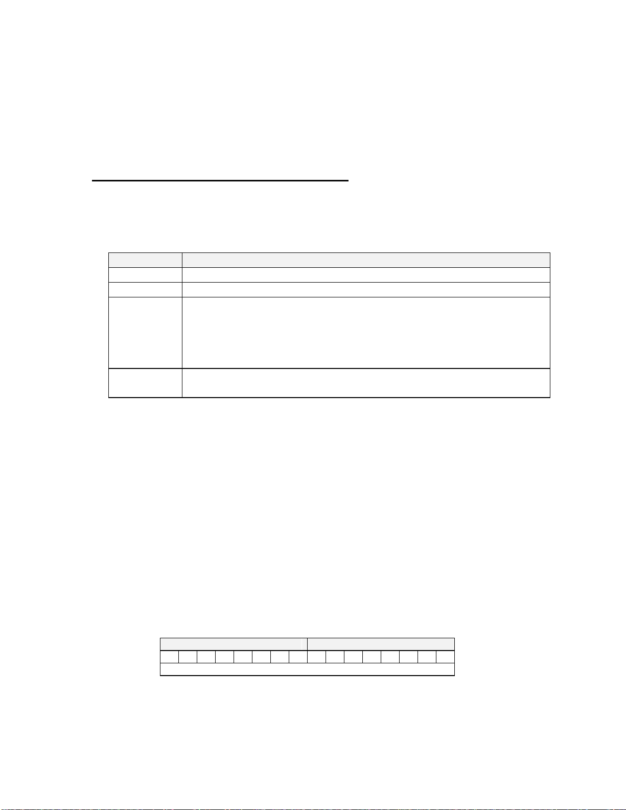
When recording the sonar and/or echo sounder data to a .852 file, the following bytes are
appended and saved to the file every 'shot':
Byte #
Description
0 to 99
File Header (100 Bytes)
100 to 111
Sonar / Echo Sounder Return Data Header (12 Bytes)
112 to xxxx
Sonar / Echo Sounder Return Echo Data
(0, 252 or 500 Bytes)
xxxx = 112+above number
Byte xxxx always = 0xFC (Termination Byte from sonar or echo
sounder)
xxxx+1
to yyyy
Zero Fill
yyyy = 127, 383 or 639
FILE HEADER
Bytes 0 through 99 contain the following File Header information:
0 ASCII '8'
1 ASCII '5'
2 ASCII '2'
3 nToReadIndex - Index for Number of Data Bytes
0 = 0 Data Bytes (IPX data)
2 = 252 Data Bytes (IMX data)
3 = 500 Data Bytes (IGX data)
4-5 Total Bytes - number of bytes that are written to the disk for this shot
Byte 4
Byte 5
7
6
5
4
3
2
1
0
7
6
5
4
3
2
1
0
128 (for IPX), 384 (for IMX) or 640 (for IGX)

Page 2 of 5
DATA STORAGE FILE FORMAT (.852) (con't)
6-7 nToRead - Number of Bytes from the sonar or echo sounder
Byte 6
Byte 7
7
6
5
4
3
2
1
0
7
6
5
4
3
2
1
0
13 (for IPX), 265 (for IMX) or 513 (for IGX)
8-19 Date - null terminated date string (12 bytes)
"DD-MMM-YYYY"
20-28 Time - null terminated time string (9 bytes)
"HH:MM:SS"
29-32 Hundredth of Seconds - null terminated string (4 bytes)
".hh"
33-36 Reserved –always 0
37 Dir, Xdcr, Mode, Step
For Sonar Head (Head ID = 0x10):
Byte 37
7
6
5
4
3
2
1
0
Dir
Xdcr
Mode
Step Size
0=ccw
1=cw
0=Dn
1=Up
0 = Sector (IGX)
1 = Polar (IMX)
0 = 2.25 Deg (Slow)
1 = 4.5 Deg (Fast)
For Echo Sounder (Head ID = 0x11):
Byte 37
7
6
5
4
3
2
1
0
N/A
N/A
Mode
N/A
0
0
0 = IGX
1 = IMX
0
38 Start Gain
0 to 40 in 1 dB increments
39 (Sector Size)/3
For Sonar Head (Head ID = 0x10):
0 to 102 = 0 to 306 Degrees in 3 degree increments
For Echo Sounder (Head ID = 0x11):
Reserved –always 0

Page 3 of 5
DATA STORAGE FILE FORMAT (.852) (con't)
40 (Train Angle)/3
For Sonar Head (Head ID = 0x10):
10 to 130 = -180 to +180 Degrees in 3 degree increments
70 = 0 degrees
For Echo Sounder (Head ID = 0x11):
Reserved –always 0
41 Reserved –always 0
42 Reserved –always 20
43 Reserved –always 9
44 Pulse Length
1 to 250 in microseconds
45 Profile
0 = Off
1 = Points Only
2 = Low Mix
3 = Medium Mix
4 = High Mix
46-47 Sound Velocity
Byte 46
Byte 47
7
6
5
4
3
2
1
0
7
6
5
4
3
2
1
0
V
Sound Velocity (in meters/second) * 10
If 'V' = 0, Sound Velocity = 1500.0 m/s
If 'V' = 1, Sound Velocity = [((Byte 46 & 0x7F)<<8) | (Byte 47)]/10.0
48-79 User Text - null terminated text string (32 bytes)

Page 4 of 5
DATA STORAGE FILE FORMAT (.852) (con't)
80-81 ROV Depth
Byte 80
Byte 81
7
6
5
4
3
2
1
0
7
6
5
4
3
2
1
0
D
ROV Depth * 10
If 'D' = 0, ROV Depth not available
If 'D' = 1, ROV Depth = [((Byte 80 & 0x7F)<<8) | (Byte 81)]/10
82 ROV Depth Units
‘M’ = Meters
‘F’ = Feet
83-84 ROV Heading
Byte 83
Byte 84
7
6
5
4
3
2
1
0
7
6
5
4
3
2
1
0
H
ROV Heading * 10
If 'H' = 0, ROV Heading not available
If 'H' = 1, ROV Heading = [((Byte 83 & 0x7F)<<8) | (Byte 84)]/10
85-86 ROV Turns Counter
Byte 85
Byte 86
7
6
5
4
3
2
1
0
7
6
5
4
3
2
1
0
T
ROV Turns Counter + 100
If 'T' = 0, ROV Turns Counter not available
If 'T' = 1, ROV Turns Counter = [((Byte 85 & 0x7F)<<8) | (Byte 86)] - 100
87 Operating Frequency
For Sonar Head (Head ID = 0x10):
0 = 675kHz
1 = 850kHz
For Echo Sounder (Head ID = 0x11):
0 = 675kHz
88 Head ID
0x10 = Sonar Head
0x11 = Echo Sounder
89-99 Reserved - always 0

Page 5 of 5
DATA STORAGE FILE FORMAT (.852) (con't)
SONAR / ECHO SOUNDER RETURN DATA HEADER
SONAR / ECHO SOUNDER RETURN ECHO DATA
ZERO FILL
The following bytes contain the Sonar / Echo Sounder Return Data that is acquired
directly from the sonar head or echo sounder serial COM port (refer to the Model 852
Serial Interface Specification):
If Header is ASCII ‘IPX’:
Bytes 100 through 112 (13 bytes)
Bytes 113 through 127 (15 bytes –Zero Fill)
If Header is ASCII 'IMX':
8-Bit
Bytes 100 through 364 (265 bytes)
Bytes 365 through 383 ( 19 bytes - Zero Fill)
If Header is ASCII 'IGX':
8-Bit
Bytes 100 through 612 (513 bytes)
Bytes 613 through 639 ( 27 bytes - Zero Fill)
Page 1 of 8
IMAGENEX TECHNOLOGY CORP. 05FEB16
MODEL 852 DIGITAL ECHO SOUNDER
SERIAL INTERFACE SPECIFICATION (v1.04)
OVERVIEW
The Model 852 Digital Echo Sounder communicates over a 2-wire differential RS-485
serial data transmission line or optionally a half-duplex RS-232 data line. To interrogate
the echo sounder and receive echo data, a Switch Data Command string is sent via a serial
command program at a baud rate of 115200 bps, No Parity, 8 Data Bits and 1 Stop Bit.
When the Switch Data command is accepted, the echo sounder transmits, receives and
sends its return data back to the commanding program.
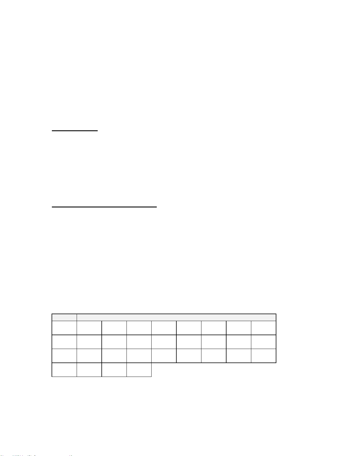
SWITCH DATA COMMAND
The echo sounder accepts up to 27 bytes of switch data from the serial interface and must
see the switch data header (2 bytes: 0xFE and 0x44 HEX) in order to process the
switches. The echo sounder will stop accepting switch data when it sees the termination
byte (0xFD HEX). The termination byte must be present for the echo sounder to process
the switches.
Note: the Termination Byte is the only switch value allowed
to have a value of 0xFD. All other switches should be set
higher or lower than 0xFD (253 Decimal) so they are not
interpreted as a termination byte!
Byte #
Description
0 –7
0xFE
0x44
Head
ID
Range
Reserved
0
Reserved
0
Master/
Slave
Reserved
0
8 –15
Start
Gain
Reserved
0
Absorp-
tion
Reversed
0
Reserved
0
Reserved
0
Pulse
Length
Profile
MinRange
16 –23
Reserved
0
Reserved
0
External
Trigger
Data
Points
Reserved
0
Reserved
0
Profile
Reserved
0
24 –26
Switch
Delay
Freq-
uency
Term.
0xFD
Table 1 Model 852 Switch Data Command To Echo Sounder
Table of contents


