Bennett 621 User manual

Bennett 1218 E. Pontaluna Road, Spring Lake, MI 49456
USA 800-235-7618 ~ Outside USA 231-798-1310
sales@bennettpump.com ~ www.bennettpump.com
BENNETT 621 INTERCONNECTION BOX
(GENERIC CURRENT LOOP FUEL INTERFACE)
INCLUDES INSTRUCTIONS FOR THE INSTALLATION OF 1 TO 24 FUEL POSITIONS AND SERVICING THE 621
INTERCONNECTION BOX.
P/N 115763 115VAC Fuel Positions 1 through 24
P/N 104080 Fan Out Board
Installation & Service Manual
116186 Rev C 11/13/18
Only Trained Personnel May Work on This Equipment
READ THIS MANUAL
This manual has important information for safe installation and operation of this equipment. Read and understand this manual
before applying power. Keep this manual and tell all service personnel to read this manual. If you do not follow the instructions,
you can cause bodily injury, death, or damage to the equipment.

Bennett 1218 E. Pontaluna Road, Spring Lake, MI 49456
USA 800-235-7618 ~ Outside USA 231-798-1310
sales@bennettpump.com ~ www.bennettpump.com
The material included in this installation manual is accurate at the date of publication. The intent of this manual is
to assist. If further assistance is required, please contact the Bennett Technical Service Department at 1-800-423-
6638.
Bennett Marketing Services can be contacted by mail, facsimile, telephone or e-mail at the locations specified
below:
Bennett Pump Company
Marketing Services
1218 East Pontaluna Road
Spring Lake, MI 49456
Telephone from USA 1-800-235-7618
Telephone from outside USA 231-798-1310, Extension 287 or 269
Customer Service USA 231-719-6050; Facsimile USA 231-799-6202
Website: www.bennettpump.com
For new manuals, visit our web page at www.bennettpump.com
IMPORTANT
Examine the shipment immediately upon arrival to make certain there has been no damage or loss in transit.
Bennett Pump Company, as shipper, is not liable for the hazards of transportation. Please make damage claims
directly to the truck line.
NOTICE: This device complies with part 15 of the FCC rules. Operation is subject to the following two conditions:
(1) This device may not cause harmful interface, and (2) this device must accept interference received, including
interference that may cause undesired operation.
Revision
Date
Description
A
12/1/11
Original Document
B
9/11/18
Added Hazardous Locations, Codes & Standards, Unauthorized Alteration of Bennett
Products, and Abbreviations & Acronyms sections.
Updated Wiring Diagram P2529 to Rev E
C
11/12/18
Add Fan Out Board

Bennett 621 Interconnection Box Instruction & Service Manual Table of Contents
i
TABLE OF CONTENTS
TABLE OF CONTENTS I
SECTION 1: SAFETY INFORMATION 1
General Information.......................................................................................................................................................................................................2
Hazardous locations ......................................................................................................................................................................................................2
Codes and Standards ....................................................................................................................................................................................................2
Unauthorized Alteration of Bennett Products....................................................................................................................................................2
Abbreviations and Acronyms.....................................................................................................................................................................................2
SECTION 2: PRODUCT INTRODUCTION 3
Features...............................................................................................................................................................................................................................3
Specifications....................................................................................................................................................................................................................3
621 Interconnection Box Configurations ..............................................................................................................................................................3
Hardware Connections .................................................................................................................................................................................................3
Pump Controller Assembly 621 Box .......................................................................................................................................................................4
SECTION 3: INSTALLATION INSTRUCTIONS 9
621 Interconnection Box - Recommended Equipment and Materials.....................................................................................................9
How To Mount the 621 Interconnection Box .....................................................................................................................................................9
AC Power Requirements ..............................................................................................................................................................................................9
AC Power Wiring.......................................................................................................................................................................................................... 10
How to Connect Dispenser Fuel Communication Wires............................................................................................................................. 10
Connect Data Distribution Box Communication Wires................................................................................................................................ 10
Connect RS485 Communication Wires To POS Interface........................................................................................................................... 11
How to Start-Up the 621 Interconnection Box................................................................................................................................................ 11
Connection Diagram .................................................................................................................................................................................................. 12
SECTION 4: SERVICE INSTRUCTIONS 13
LED Diagnostics............................................................................................................................................................................................................ 13
Helpful Programming Hints .................................................................................................................................................................................... 14
SECTION 5: PARTS 15
How To Place an Order for Parts........................................................................................................................................................................... 15
Parts List........................................................................................................................................................................................................................... 15

Bennett 621 Interconnection Box Instruction & Service Manual Table of Contents
ii
Page Intentionally Left Blank

Bennett 621 Interconnection Box Instruction & Service Manual Safety Information
1
SECTION 1: SAFETY INFORMATION
For safe installation of this equipment, read and understand all dangers, warnings, and cautionary information. Save this safety information in a
readily accessible location. Look for the following warnings throughout the manual:
Red and White “DANGER” means: If you do not follow the instructions, severe injury or death will occur.
Orange and Black “WARNING” means: If you do not follow the instructions, severe injury or death can occur.
Yellow and Black “CAUTION” means: If you do not follow the instructions, damage can occur to the dispenser.
Blue and White “IMPORTANT” means: Helpful tips and other recommendations on equipment installation, usage, and maintenance should
be observed.
DANGER PELIGRO DANGER
FIRE, EXPLOSION, INJURY, OR DEATH WILL OCCUR IF FUEL FILTERS ARE
CHANGED BY UNTRAINED PERSONNEL. MAKE SURE, ONLY TRAINED
PERSONNEL CHANGE FILTERS.
TO PREVENT INJURY TO YOU FROM VEHICLES AND ONLOOKERS,
ALWAYS PLACE A BARRIER AROUND THIS EQUIPMENT BEFORE
PERFORMING SERVICE OR MAINTENANCE.
GASOLINE AND FUEL ETHANOL IS FLAMMABLE. NO SMOKING OR
OPEN FLAME.
FUEL ETHANOL IS POISONOUS AND SHOULD NOT BE INGESTED.
DISCONNECT ALL POWER, RELIEVE PRESSURE TO THIS EQUIPMENT,
AND ASSOCIATED COMPRESSOR DURING INSTALLATION, SERVICE, OR
ANY MAINTENANCE I.E., CHANGING FILTERS.
WARNING ADVERTENCIA MISE EN GARDE
You must have training in the installation, service, or maintenance of
this equipment (dispenser, pump, console, control box, or submerged
pump) before working on it. Maintenance repairs must be done by
authorized personnel only. Warranty work may only be performed by
Bennett certified technicians.
To prevent electric shock, keep the electrical parts of the dispenser dry.
Electronic components are static sensitive. Use only proper static
precautions (e.g. static straps) before working on the equipment.
The emergency shut-off valve (also called the fire valve, shear valve, or
impact valve) must be closed when service or maintenance is performed
on this equipment.
You must have training in the operation and programming of this
dispenser before using it. READ THE OPERATORS MANUAL.
Make sure this equipment is correctly grounded. Failure to do will cause
injury or damage equipment or improper operation. Improper
grounding voids the warranty.
When anchoring the dispenser, always level the dispenser with shims
before bolting to the island. DO NOT shim the middle of base rails to
bolt down the dispenser.
Make sure that all labels, decals, warning, cautions, and instructions are
fastened to the equipment. Order replacement labels from Bennett.
CAUTION PRECAUCIÓN MISE EN GARDE
Do not drill holes in fuel dispensers. Holes can cause failure of the
electronic equipment. THE WARRANTY WILL BECOME VOID. Use only
adhesive backed sign mounting brackets.
IMPORTANT IMPORTANTE IMPORTANT
All trained technicians must work in accordance to all requirements,
standards, and guidelines specified by the suppliers Environmental
Standards® Health, Safety, Security & Environment (HSSE) policies.
Note: Bennett Pump highly recommends all technicians observe HSSE
policies defined by the supplier. Bennett Pump does not impose any
restrictions or additional requirements contained in Environmental
Standards® Health, Safety, Security & Environment (HSSE) policies.
!! READ AND UNDERSTAND ALL WARNING LABELS ATTACHED TO THE DISPENSER !!

Bennett 621 Interconnection Box Instruction & Service Manual Safety Information
2
GENERAL INFORMATION
Read this manual carefully and read all tags/labels attached to the 621 Interconnection Box before starting any maintenance and/or service. A
controller that is not properly maintained will not perform properly and will void the Bennett limited warranty.
Before installation, operation, maintenance and/or service ensure that protection against lighting strikes are in accordance with the American
Petroleum Institute Recommended Practice RP 2003, Protection Against Ignitions Arising out of Static, Lightening, and Stray Currents.
Service of the Bennett products and all accessories (e.g. Nozzles, Hoses, and Breakaways) must be performed by a technician who is trained in
accordance to all codes, standards, and regulations.
HAZARDOUS LOCATIONS
For safe operation, ensure that the dispenser is in a classified area as detailed below per NFPA 30, Flammable and Combustible Liquids Code and
NFPA 70, National Electric Code. For further information on the classification of locations for Fuel Dispensers, see NFPA 30, Flammable and
Combustible Liquids Code.
CODES AND STA NDAR DS
Follow all local, state, and federal requirements for installation of all equipment.
API 2003 –Protection Against Ignitions Arising Out of Stray, Lightning, and Stray Currents
NFPA 30 –Flammable and Combustible Liquids Standard
NFPA 30A –Motor Fuel Dispensing Facilities Standard
NFPA 70 –National Electric Code
International Fire Code –2000 Edition
UNAUTHORIZE D ALTERAT IO N OF BEN NETT PRODU CTS
DANGER: BEFORE PERFORMING ANY TYPE OF SERVICE TO THE DISPENSERS, BE SURE TO SHUT OFF ALL ELECTRICAL SUPPLIES AND
SECURE THEM IN THE OFF POSITION. CLOSE ALL VALVES IN INCOMING PIPING. MAINTENANCE MUST BE PERFORMED
BY TRAINED PERSONAL ONLY.
Bennett Pump Company products are designed to meet or exceed the standards of Underwriters Laboratories, Inc., Federal Communication
commission, and National Institute of Standards and Technology. Compliance with these standards protects the operator and the consumer from
personal injury and ensure an accurate delivery of product. Any deviation from the use of authorized replacement parts or alteration of a designed
product configuration may cause personal injury, death or the revocation of one or all of the above approvals.
Bennett Pump Company will not assume responsibility or liability for any consequential injury or damage caused by the unauthorized alteration of
its products.
ABBREVIATIO NS A ND ACRONY MS
TERM
DESCRIPTION
AC
Alternating Current
API
America Petroleum Institute
ASR
Automatic Statistical Reconciliation
DC
Direct Current
DCR
Debit Credit Reader
EPA
Environmental Protection Agency
GCL
Generic Current Loop
Hz
Hertz
NEC
National Electrical Code
NFPA
National Fire Protection Agency
NPT
National Pipe Taper or National Pipe Thread
NREL
National Renewable Energy Laboratory
OEM
Original Equipment Manufacturer
POS
Point-of-Sale
PEI
Petroleum Equipment Institute
PVC
Polyvinyl Chloride
RAM
Random Access Memory
RFI
Radio Frequency Interference
THHN
Thermoplastic High Heat-resistant Nylon-coated
UL
Underwriters Laboratories, Inc.
VAC
Voltage Alternating Current
VDC
Voltage Direct Current
VOM
Volt-Ohm Meter

Bennett 621 Interconnection Box Instruction & Service Manual Product Introduction
3
SECTION 2: PRODUCT INTRODUCTION
The Bennett Model 621 Interconnection Box is an interface device for third party point-of-sale systems. It allows the customer to use Bennett Fuel
Dispensing equipment with Consoles supporting the Generic Current Loop Fuel protocol.
FEATURE S
The 621 Interconnection Box communicates with 1 to 16 fueling positions.
The 621 has an external wall mount power supply that converts 120/240VAC 50/60Hz to 12VDC 0-1.0A. The power supply limits the incoming
voltage so the 621 board is protected from possible surge conditions.
The 621 is “Plug and Play”, meaning that additional programming is not required after the installation is complete.
Four LED indicators to aid the Bennett technician to troubleshoot site occurrences.
The Fan-Out Circuit Board provides additional terminal strips for RS485 Data Communication.
SPECIFIC ATIONS
621 Dimensions (length x width x height).................................................................................................12in x 12in x 4in (30.5cm x 30.5cm x 10.2 cm)
Fan-Out Circuit Board Dimensions (length x width) ......................................................................................................................................8.5in x 3.4in
Operang Temperature......................................................................................................................................................0C to +40C / +32F to +104F
Storage Temperature......................................................................................................................................................... -20C to +65C / -4F to +149F
Operang Humidity ..................................................................................................................................................................0 to 95% Non-Condensing
Storage Humidity .................................................................................................................................................................30% to 70% Non-Condensing
AC Power Input Voltage...................................................................................................................................................................120/240VAC 50/60Hz
Fuse Amperage ............................................................................................................................................................................................... 1.0 A / 0.5A
Protocols (Fuel Only)........................................................................................................................................................................Generic Current Loop
621 INTERCONNECTIO N BOX CONFIGURATIO NS
Fuel Only
Fuel and DCR with use of POS hardware supporting the Generic Current Loop protocol.
HARDWARE CO NNECTION S
.
Data Distribution Box
BENNETT 621 INTERCONNECTION BOX
Dispenser
Generic Current Loop
(Up to 24 Fueling Points)
AC Power Module
Fuel Communication
Incoming 12 VDC
Fan-Out Board
Interconnection Box
RS485 Data
RS485 Data
Bennett 621 Interconnection Box Instruction & Service Manual Product Introduction
4
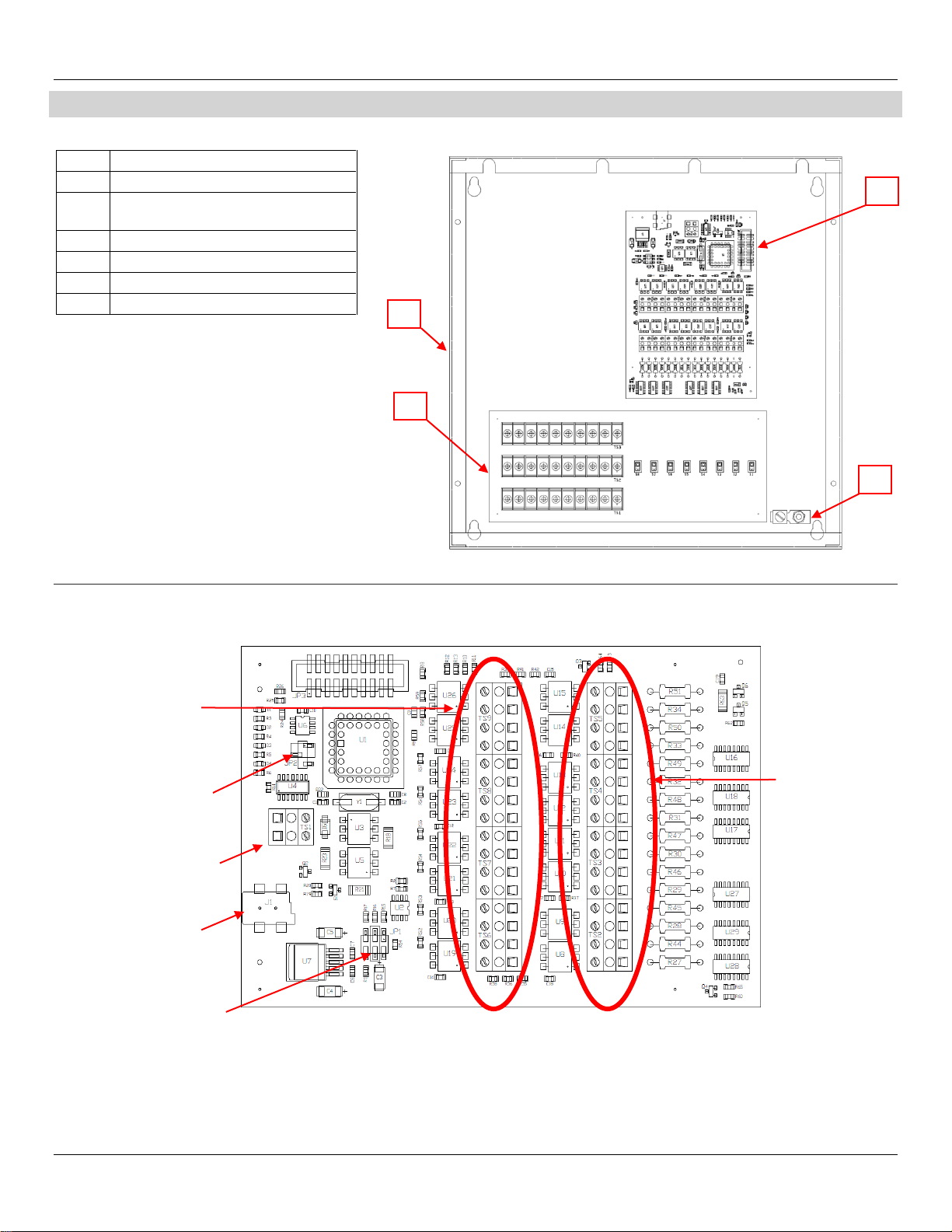
PUMP CONTROLLER ASSEMBLY 621 BOX
The 621 Interconnection Box is used to interface with third party point-of-sale systems and supports the Generic Current Loop Fuel protocol.
621 CIRCUIT BOARD ASSE MBLY
For locations with 1 through 16 Fueling Points.
ITEM
DESCRIPTION
1
Enclosure
2
Circuit Board Assembly 621 Generic
Current Loop Adaptor
3
Circuit Board Assembly Fan Out Board
4
Grounding Lug
N/A
Front Cover (Not Shown)
N/A
AC Power Module (Not Shown)
J1
AC Line Voltage Input
JP1
Current Loop Voltage
TS1
Data Communication
JP2
Run or Program Mode
TS6-TS9
Fueling Points 9-16
TS2-TS5
Fueling Points 1-8
1
2
3
4

Bennett 621 Interconnection Box Instruction & Service Manual Product Introduction
5
CONNECTOR DESCRIPTIONS
The following is a description of the connections, LED’s, and jumpers located on the 621 circuit board.
GROUNDING
A 12 AWG green earth ground wire must be connected to the green ground screw inside the enclosure. The green ground screw MUST BE within 1
Ohm of earth ground. This is located near the Fan Out Board.
IMPORTANT: Follow proper grounding procedures to reduce radio frequency interference (RFI). All Bennett equipment must be
properly grounded. Follow National Electrical Code, Article 514-7 for grounding requirements as well as Bennett’s
grounding procedures. It is UNACCEPTABLE to rely on the conduit for these grounding requirements.
J1 AC LINE VOLTAGE INPUT
The AC Power Module is used to provide AC power to the 621 board at the J1 connector. Only one dispenser electronics Hot and Neutral needs to
be pulled per dispenser.
Each 621 Interconnection Box uses one 120V, 50/60 Hz, or 240V, 50/60 Hz circuit for power. Make sure the power source has the correct frequency
and voltage
JP1 CURRENT LOOP VOLTAGE
The JP1 is a 3-pin jumper used for current loop voltage. The center two pins MUST be set for operation in the field. Note: Failure to set jumper in
the center position will result in improper operation of the 621 board.
JP2 RUN MODE OR PROGRAM MODE
The JP2 is a 3-pin jumper used to select run mode for field operation or program mode for flash programming (BENNETT USE ONLY).
Run Mode –This mode MUST be used for operation in the field.
Program Mode –This mode is exclusively used for flash programming at Bennett Pump Company. DO NOT CHANGE THIS SETTING! The board will
not operate correctly if the jumper is in this position.NOT FOR FIELD USE!
Pin Description
1 & 2 (top) Run Mode –Field Use Only
2 & 3 (bottom) Program Mode–Bennett Use Only
TS1 POS COMMUNICATION
Terminal strip TS1 connects to the data distribution cabinet. There is a (+) positive and (–) negative connection.
Pin Description
1 (orange) (+) Positive
2 (yellow) (-) Negative
OR
5 1
6 2
(+ Positive)
(- Negative)
GROUND SCREW
Bennett 621 Interconnection Box Instruction & Service Manual Product Introduction
6
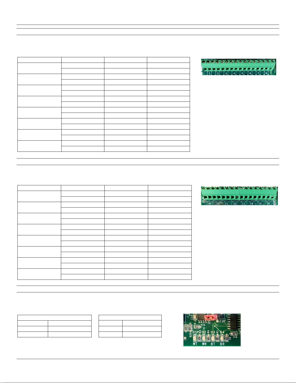
TS2 - TS5 (POSITIONS 1-8) DISPENSER COMMUNICATION
Terminal blocks TS2 through TS5 are labeled as (Positions 1 - 8) that are used for Fueling Points 1 through 16. Each terminal strip position will
supply two fueling points one (+) positive and one (–) negative connection. Note: A fueling point is one side of a dispenser and a two-sided
dispenser would have two fueling points.
TS6 - TS7 (POSITIONS 9-12) DISPENSER COMMUNICATION
Terminal block TS6 - TS7 (Positions 9-12) are used for Fueling Points 17 through 24. Each terminal strip position will supply two fueling positions
one (+) positive and one (–) negative connection. Note: A fueling point is one side of a dispenser and a two-sided dispenser would have two fueling
points.
TERMINAL POSITION
FUELING POINT
COLOR
PIN
9
17 & 18
Orange
(+) positive
17 & 18
Yellow
(-) negative
10
19 & 20
Orange
(+) positive
19 & 20
Yellow
(-) negative
11
21 & 22
Orange
(+) positive
21 & 22
Yellow
(-) negative
12
23 & 24
Orange
(+) positive
23 & 24
Yellow
(-) negative
13
NOT USED
Orange
(+) positive
NOT USED
Yellow
(-) negative
14
NOT USED
Orange
(+) positive
NOT USED
Yellow
(-) negative
15
NOT USED
Orange
(+) positive
NOT USED
Yellow
(-) negative
16
NOT USED
Orange
(+) positive
NOT USED
Yellow
(-) negative
LEDs DISPENSER & POS COMMUNICATION
The 621 Circuit Board has surface mount LEDs that are used for troubleshooting. If the console and dispensers are communicating, all LED’s will be
flashing. If not communicating with the POS or Dispenser then the “Transmit” LED will be on constantly and the “Receive” LED will be off. Refer to
the troubleshooting section for more information.
TERMINAL POSITION
FUELING POINT
COLOR
DESCRIPTION
1
1 & 2
Orange
(+) positive
1 & 2
Yellow
(-) negative
2
3 & 4
Orange
(+) positive
3 & 4
Yellow
(-) negative
3
5 & 6
Orange
(+) positive
5 & 6
Yellow
(-) negative
4
7 & 8
Orange
(+) positive
7 & 8
Yellow
(-) negative
5
9 & 10
Orange
(+) positive
9 & 10
Yellow
(-) negative
6
11 & 12
Orange
(+) positive
11 & 12
Yellow
(-) negative
7
13 & 14
Orange
(+) positive
13 & 14
Yellow
(-) negative
8
15 & 16
Orange
(+) positive
15 & 16
Yellow
(-) negative
FUEL CONTROLLER COMMUNICATION
LED
FUNCTION
D1 (WT)
POS GCL Transmit
D2 (WR)
POS GCL Receive
DISPENSER COMMUNICATION
LED
FUNCTION
D3 (BT)
Bennett Transmit
D4 (BR)
Bennett Receive

Bennett 621 Interconnection Box Instruction & Service Manual Product Introduction
7
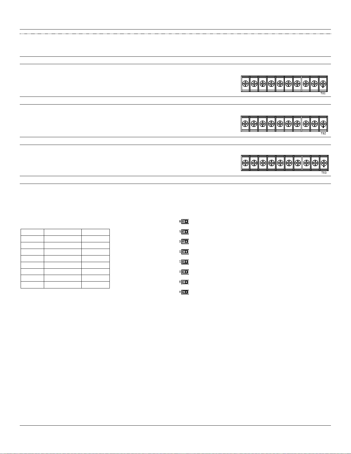
FAN-OUT CIRCUIT BOAR D
The Fan-Out Circuit Board in the Bennett Interconnect Box provides a connection to the dispenser’s payment module. The Fan-Out Circuit Board
has three sets of 10-position screw terminal strips.
TS1 connects the DATA (+) Positive for each dispenser.
TS2 connects the DATA Return for each dispenser. (If Required by Interface)
TS3 connects the DATA (-) Negative for each dispenser.
The board also provides switches for diagnostic purposes. Note: All switches must be in the ON position. If one of the switches is in the OFF
position the point-of-sale will not be able to communicate to the dispenser connected to that DATA loop.
The Debit/Credit Terminal’s connect to the Fan-Out Board. One bad card reader terminal has the potential to take down the entire card system
since they are all in a common parallel loop. The switches are used to remove a suspected "bad" terminal from this data loop. Turning a switch off
will actually remove two terminals (one dispenser) from the data loop. This should help facilitate troubleshooting down to a particular dispenser.
TS3
Data (-) Negative
Switches 1 -8
NOT USED
TS1
Data (+) Positive
TS2
Data Return
Bennett 621 Interconnection Box Instruction & Service Manual Product Introduction
8
CONNECTOR DESCRIPTIONS
The following is a description of the connections and switches located on the Fan-Out Circuit board.
TS1 RS485 COMMUNICATION –DATA (+) POSITIVE
A 10-poition screw terminal strip provides a DATA (+) positive connection for each debit/credit terminal.
TS2 RS485 COMMUNICATION –GROUND
A 10-position screw terminal strip provides a GROUND connection for each debit/credit terminal.
TS3 RS485 COMMUNICATION –DATA (-) NEGATIVE
A 10-position screw terminal strip provides a DATA (-) negative connection for each debit/credit terminal.
S1-S8 SWITCH
Switches S1 - S8 on the circuit board are used for diagnostic purposes. Note: All switches must be in the ON position. If one of the switches is in the
OFF position the point-of-sale will not be able to communicate to the dispenser connected to that DATA loop. All switches are turned OFF by
default. Note: Not used on Pacific dispensers.
To turn a switch ON move the switch to the right.
To turn a switch OFF move the switch to the left.
SWITCH
DESCRIPTION
SETTING
1
Address 1
OFF / ON
2
Address 2
OFF / ON
3
Address 3
OFF / ON
4
Address 4
OFF / ON
5
Address 5
OFF / ON
6
Address 6
OFF / ON
7
Address 7
OFF / ON
8
Address 8
OFF / ON
Bennett 621 Interconnection Box Instruction & Service Manual Installation Instructions
9
SECTION 3: INSTALLATION INSTRUCTIONS
Bennett Pump Dispensers are to be installed by trained technicians. All technicians must be aware of ALL safety instructions. If you are not a
Bennett trained technician, please contact Bennett Technical Support at 1-800-423-6638 for training information.
Identifying the features of the unit prior to installation will provide an understanding of how to perform an accurate installation. Follow the steps
below to install a 621 Interconnection Box.
621 INTERCON NECTION BOX - RECOMME NDE D EQUIP MENT AND M ATERIAL S
The items listed below are recommended for proper installation of the Bennett 621 Interconnection Box. Note: Consult the control console and/or
point-of-sale manufacturer for component requirements.
P/N 115763 –621 Pump Controller
Power Supply Cable (included)
Dispenser Communication Wires - 18 AWG or larger gas and oil resistant (customer supplied)
Jumpers
Voltmeter
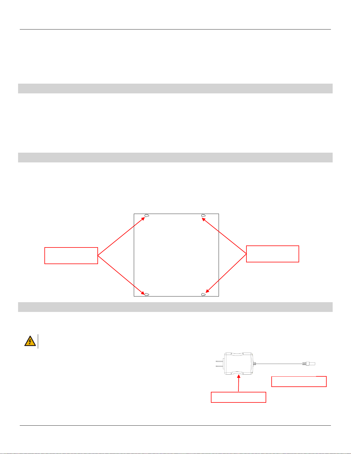
HOW TO MOUNT THE 621 INTERCONNECTION BOX
The 621 Interconnection Box measures 12” x 12” x 4”. The enclosure requires four mounting screws. These four screws are on 10 ½” by 10 ½”
centers.
Note: When installing a 621 Interconnection Box pay attention to the locations of the AC Power Module port.
1. Layout screws on wall 10 ½” by 10 ½” centers and slide enclosure’s 4 keyhole mounting slots over screws and tighten.
2. Slide enclosure’s four keyhole-mounting slots over screws and tighten.
3. After installation is complete, replace cover using the screws provided.
AC POWER REQUIREMENTS
Each 621 Interconnection Box uses one 120V, 50/60 Hz, or 240V, 50/60 Hz circuit for power. Make sure the power source has the correct frequency
and voltage. Connect the AC Power Module to the J1 connector on the 621 board. Only one dispenser electronics Hot and Neutral needs to be
pulled per dispenser.
WARNING: ALL DISPENSER AC POWER CIRCUITS (FOR REMOTES ONLY) MUST BE ON THE SAME PHASE OR DAMAGE WILL OCCUR TO
THE DISPENSER CPU OR THE SUB-PUMP RELAY BOX.
1. The AC Power Module must be connected to a dedicated AC receptacle.
2. AC voltage must be a minimum of 100VAC or a maximum of 240VAC ~ 50/60Hz
3. A 12-gauge green ground wire must be installed to the lug provided in the box.
INCOMING 12VDC
AC Power Module
INCOMING 12VDC
MOUNTING HOLES
MOUNTING HOLES

Bennett 621 Interconnection Box Instruction & Service Manual Installation Instructions
10
AC POWER WIRING
WARNING: ABSOLUTELY NO DAISY CHAINING COMMUNICATION DATA WIRES, ORANGE AND YELLOW 18AWG. DAMAGE TO THE
CONTROL CONSOLE MAY RESULT.
WARNING: MAKE SURE THE 621 INTERCONNECTION BOX IS PROPERLY GROUNDED WITH 12AWG GREEN EARTH GROUND WIRE IS
CONNECTED TO THE GREEN GROUND SCREW INSIDE THE ENCLOSURE. FAILURE TO PROPERLY GROUND THE
EQUIPMENT CAN CAUSE INJURY OR DAMAGE TO THE EQUIPMENT AND WILL VOID THE BENNETT LIMITED WARRANTY.
Follow proper grounding procedures to reduce radio frequency interference (RFI). All Bennett equipment must be properly grounded. Follow
National Electrical Code, Article 514-7 for grounding requirements as well as Bennett’s grounding procedures. It is UNACCEPTABLE to rely on the
conduit for these grounding requirements.
1. A 12 AWG green earth ground wire must be connected to the green ground screw inside the enclosure. The green ground screw MUST BE
within 1 Ohm of earth ground. This is located near the AC power terminal.
2. Connect the AC Power Module to J1.
HOW TO CONNE CT DISPENSER FUEL COMMUNICATIO N WIRES
CAUTION: All communication wires must be 18 AWG or larger gas and oil resistant stranded copper THHN per National Electrical
Code.
CAUTION: Absolutely no daisy chaining (orange and yellow 18-AWG) communication data wires. Damage to the control console
may result.
CAUTION: DO NOT use wire nuts. Splicing with wire nuts can cause communication failure, system failure, and may void
warranty.
Dispenser fuel communication wires for fueling positions 1 through 24 terminate directly to the 621 Circuit Board. Each fueling point has a positive
(orange) and negative (yellow) connection. A Fueling Point is one side of a dispenser. A two-sided dispenser would have two fueling points. Each
fueling position is labeled on the circuit board as shown in the figure below. Fueling points 1 through 16 are labeld as 1 through 8. Fueling points 17
through 24 are labeld as 9-12. (e.g. Fueling point 1 & 2 are labeled as 1, fueling point 3 & 4 are labeled as 2 and etc. Refer to the 621 Wiring
Diagram (P2915) for detailed information.
1. Connect data wires to terminal strip positions 1-12. Note: Each terminal strip channel will supply two fueling positions. This will allow a
maximum of 24 fueling points.
2. Connect the other end of the data wire to the 708 CPU Board or to the Current Loop Personality Module located on the 819/919 CPU Board.
CONNECT DAT A DISTRIBUTION BO X COMMU NIC ATION WIRES
The following description is used to connect a Data Distribution Box via Generic Current Loop communication. Field connections will depend on the
generic current loop equipment available at the site. Note: For any other POS that communicates using Bennett protocol must be programmed on
Channel 1. Refer to the 621 Wiring Diagram (P2915) for detailed information.
1. Connect 1 x 18ga. Orange (+ positive) wire to the 621 CPU Board at TS1, + positive as indicated on the diagram. Connect the other end to the
Data Distribution Box.
2. Connect 1 x 18ga. Yellow (- negative) wire to the 621 CPU Board at TS1, - negative as indicated on the diagram. Connect the other end to the
Data Distribution Box.
INCOMING 12VDC VOLTAGE

Bennett 621 Interconnection Box Instruction & Service Manual Installation Instructions
11
CONNECT RS485 COMMUNICATION WIRES
The following description is used for a RS485 payment communication. Field connections will depend on the Generic Current Loop Equipment
Available at the Site. Please read and understand other manufacturer information prior to installation. Refer to the 621 Wiring Diagram (P2915) for
detailed information.
Note: RS-485 wires should be twisted together no less than 3 turns per foot to reduce the effects of electrical noise on the
communication circuit. Due to the risk of noise, causing possible problems with communication, Bennett highly recommends
the use of twisted wires, but does not require it. Note: Belden shielded cable is accepted but the “drain” must not be
terminated.
1. Connect 1 x 18ga. (+ positive) wire to the Fan Out Board at TS1, (+) positive as indicated on the diagram. Connect the other end to the 819/919
CPU Board at TS3, Terminal 1.
2. Connect 1 x 18ga. (- negative) wire to the Fan Out Board at TS3, (-) negative as indicated on the diagram. Connect the other end to the
819/919 CPU Board at TS3, Terminal 3.
HOW TO START -UP THE 621 INTERCONNECTIO N BOX
Refer to the Diagnostics & Troubleshooting section for a detailed description and/or if an error occurs. If a problem occurs, refer to the service and
troubleshooting section for more information or call Bennett Technical Support at 1-800-423-6638.
1. Apply power to dispensers, program them for operation, and address the fueling positions accordingly. See “Helpful Programming Hints” on
page 12.
Refer to your dispenser operator’s manual or X19 technical and dispenser programming manual for detailed programming instructions.
2. Apply power to POS, Site Controller, and Data Distribution Cabinet. Program and initialize POS as required. See “Helpful Programming
Hints” on page 12.
3. Verify that the communication LED’s are flashing rapidly on the 621 board. Refer to page 13 for Troubleshooting Diagnostics.
FUEL POSITION 17 & 18 (-) YELLOW
FUEL POSITION 17 & 18 (+) ORANGE
FUEL POSITION 19 & 20 (-) YELLOW
FUEL POSITION 19 & 20 (+) ORANGE
FUEL POSITION 23 & 24 (-) YELLOW
FUEL POSITION 23 & 24 (+) ORANGE
FUEL POSITION 21 & 22 (-) YELLOW
FUEL POSITION 21 & 22 (+) ORANGE
(-) YELLOW TO DATA DISTRIBUTION CABINET
(+) ORANGE TO DATA DISTRIBUTION CABINET
FUEL POSITION 1 & 2 (-) YELLOW
FUEL POSITION 1 & 2 (+) ORANGE
FUEL POSITION 3 & 4 (-) YELLOW
FUEL POSITION 3 & 4 (+) ORANGE
FUEL POSITION 5 & 6 (-) YELLOW
FUEL POSITION 5 & 6 (+) ORANGE
FUEL POSITION 7 & 8 (-) YELLOW
FUEL POSITION 7 & 8 (+) ORANGE
FUEL POSITION 9 & 10 (-) YELLOW
FUEL POSITION 9 & 10 (+) ORANGE
FUEL POSITION 11 & 12 (-) YELLOW
FUEL POSITION 11 & 12 (+) ORANGE
FUEL POSITION 13 & 14 (-) YELLOW
FUEL POSITION 13 & 14 (+) ORANGE
FUEL POSITION 15 & 16 (-) YELLOW
FUEL POSITION 15 & 16 (+) ORANGE
NOT USED
NOT USED
NOT USED
NOT USED
NOT USED
NOT USED
NOT USED
NOT USED
(-) NEGATIVE
RETURN
(+) POSITIVE

Bennett 621 Interconnection Box Instruction & Service Manual Installation Instructions
12
CONNECTION DIAGRAM

Bennett 621 Interconnection Box Instruction & Service Manual Service Instructions
13
SECTION 4: SERVICE INSTRUCTIONS
This section describes the information provided on each diagnostic display message. Note: Displays shown throughout the
manual are examples only. Information may vary based on dispenser options.
LED DIAG NOSTICS
The 621 Circuit Board has surface mount LEDs that are used for troubleshooting. If the console and dispensers are
communicating, all LED’s will be flashing. If not communicating with the POS or Dispenser then the “Transmit” LED for that side
will be on constantly and the “Receive” LED will be off. Refer to the troubleshooting section for more information. Refer to the
figure below for LED locations. Refer to the figure below for LED locations.
LED
COLOR
DESCRIPTION
COMMUNICATION TYPE
IMAGE
D1 (WT)
Red
Generic Current Loop Transmit
Fuel Controller
D2 (WR)
Red
Generic Current Loop Receive
Fuel Controller
D3 (BT)
Red
Bennett Transmit
Dispenser Communication
D4 (BR)
Red
Bennett Receive
Dispenser Communication
LED TROUBLESHOOTING
Remember to use the LED lights as diagnostic tools. Verify that the console is programmed correctly for operation with Bennett
dispensers.
PROBLEM
CAUSES
SOLUTIONS
No LEDs are flashing
1. The 621 Board is not receiving power.
2. The console is not transmitting commands to
dispensers.
1. Ensure AC/DC power supply is
plugged in.
2. Ensure console is on and
programmed correctly.
Only D1 (WT) LED is flashing
1. Jumper JP2 is not in the RUN position.
2. The 621 Board is damaged.
1. Ensure JP2 is on the top two pins.
2. Replace the 621 Board.
D3 (BT) LED is momentarily
solid and D1 (WT) and D4
(BR) LEDs are flashing
1. Console is attempting to communicate with a
disconnected fueling position or dispenser
that is powered off.
1. Reconnect data wires or restore
power to the dispenser.
D1 (WT)
D2 (WR)
D3 (BT)
D4 (BR)

Bennett 621 Interconnection Box Instruction & Service Manual Service Instructions
14
HELPFUL PROGR AMMING HI NTS
The following contains basic communication programming procedures for a Bennett Pacific and Nucleus POS. It is EXTREMELY
important that all of the appropriate Bennett and OEM manuals be reviewed prior to operation.
To enter Manager’s Mode enter the access code <2218> and press <ENTER>.
To access a specific manager’s mode, enter the mode number and press the <MODE> key.
If multiple displays associated with the selected manager’s mode, press the <DOWN ARROW KEY> to cycle between
the displays.
To exit a specific manager’s mode and return to the idle manager’s mode, press the CANCEL key.
BENNETT PACIFIC PROGRA MMING
In order to function properly, the following settings MUST be programmed at the dispenser to communicate with the Nucleus®.
NUCLEUS PROGRAMMING
In order for the Bennett dispensers to function properly, the correct settings must be made in the pump-programming window
of the Nucleus system. Three settings in the “Pump Options” window will need to be programmed correctly in order for the
dispensers to function. These settings are TYPE, PUSH TO START, and VALID POSITIONS. Other settings in this window will not
inhibit dispenser operation. Note: Please refer to the appropriate Nucleus programming guide for complete programming
instructions.
PACIFIC CONFIGURATION
DISPENSER TYPE
PUSH-TO-START
VALID POSITIONS / GRADE MAPPING
Three Product Blender
VRB
None or Select Grade
3-High Grade, 5-Blend, 7-Low Grade
3+1 Blender
VRB Plus
None or Select Grade
1-Diesel, 4-High Grade, 5-Blend, 6-Low Grade
Three Grade Mixer
MGD Uni-Hose
None or Select Grade
1-Grade A, 2-Grade B, 3-Grade C
One Grade Non-Blender
MGD Uni-Hose
None or Select Grade
1-Grade A
Two-Grade Non-Blender
MGD Multi-Hose
None or Select Grade
1-Grade A, 2-Grade B
Three Grade Non-Blender
MGD Multi-Hose
None or Select Grade
1-Grade A, 2-Grade B, 3-Grade C
MODE
DESCRIPTION
SETTING
NOTES
21
Communication Type
3 = Generic Current Loop
Display will read “generic Loop”
22
Dispenser Address
Site Specific
Set a unique address for each fueling position. The
display will read “Generic adr xx” where “ xx ”
will be the current address for the specific fueling
position. Each fueling position may have an address
from 1-24. Each fueling position must be connected to
the appropriate position on the 621 interface board.
The 621 pools each channel on the board in search of
the correct address. Example: Channel 1 on the 621
supports address 1 & 2. Channel 2 on the 621 supports
address 3 & 4 and so on.
23
Push-To-Start
0 = Disabled
1 = Enabled
Menu code 23 controls if push-to-start is required. This
mode must be programmed to match the push-to-start
field within pump programming in the Nucleus.
99
Unit of Measure
Unit of Measurement
1 = Gallons
2 = Liters
3 = British Imperial Gallons
Decimal Placement
1 = 1000th
This menu code sets the volume unit of measurement.
Option 1 is for gallons, 2-Liters, 3-British Imperial
Gallons. Press Enter to access decimal location. Option
1 must be set to 1 (1000th) for operation with the
Nucleus.
08
Decimal Location
0 = U.S.A.
This menu code controls the decimal placement of the
monetary display values. This mode must always be set
to option 0 for operation with the Nucleus.

Bennett 621 Interconnection Box Instruction & Service Manual Parts
15
SECTION 5: PARTS
HOW TO PLACE AN OR DER FO R PARTS
To place an order for parts please contact us by mail, email, phone, fax, or web using the information provided below. Note:
Verbal orders cannot be accepted. A signed purchase order must be faxed or emailed to the Bennett Order Entry Department
Bennett Pump Company
Marketing Services
1218 East Pontaluna Road
Spring Lake, MI 49456
Telephone from USA 1-800-235-7618
Telephone from outside USA 231-798-1310, Extension 287 or 269
Customer Service USA 231-719-6050; Facsimile USA 231-799-6202
Website: www.bennettpump.com
ALL ORDERS MUST INCLUDE THE FOLLOWING INFORMATION:
Note: Many electronic circuit boards have a factory-rebuilt equivalent. All rebuilt boards have a part number prefix of “RB”.
You must use factory-rebuilt parts for all warranty service work. Please refer to the Distributor Policy Manual for
program terms and details.
1. The part number, description, and quantity are required.
2. Rebuilt parts must be used for warranty claims. Rebuilt exchange program parts are identified by a “RB” prefix to the part
number.
3. The complete “ship to” address.
4. Your company’s name and address (if different from the shipping destination) for billing purposes.
PARTS LIST
The parts listed in the table below are basic components needed for a new or existing 621 Interconnection Box. Some 621
Interconnection Boxes may require basic and/or additional materials such as bolts, fittings, etc. These items can be found in
your local hardware store. If not please feel free to contact our Bennett Customer Service Group at 1-800-719-6050.
Reference No.
Part Number
Description
QTY.
1
115763
621 Interconnection Box (Complete Assembly)
1
2
115590
621 Board Assembly
1
3
116181
Power Supply
1
Not Shown
104080
Circuit Board Assembly Fan-Out Board
1
3
2
1

Bennett 621 Interconnection Box Instruction & Service Manual Parts
16
Page Intentionally Left Blank
This manual suits for next models
2
Table of contents
Other Bennett Marine Equipment manuals

Bennett
Bennett LNG Series User manual

Bennett
Bennett H35 Series User manual

Bennett
Bennett HIGH FLOW H35 User manual

Bennett
Bennett H35 Series User manual

Bennett
Bennett BOLT Control BCI8000 User manual

Bennett
Bennett SITE MASTER EMV User manual

Bennett
Bennett BOLT Rocker BRC4000 User manual

Bennett
Bennett H35 Series User manual
Popular Marine Equipment manuals by other brands


marinco
marinco MiniVent 1000 installation instructions

ohmex
ohmex SONARMITE v3.0 manual

Faria
Faria Pilot 1 owner's manual

Dual Electronics Corporation
Dual Electronics Corporation MXD25 Installation & owner's manual

Raymarine
Raymarine H6 System installation manual

Eaton
Eaton SDR-RINT installation instructions


