greenmarine AWM-1510 User manual

USER MANUAL AWM SERIES II
AWM-1510 Marine Monitor
AWM-1710 Marine Monitor
(1st Edition 8/26/2013)
All information contained in this manual is subject to change without notice
AWM-1910 Marine Monitor

RECORD OF REVISION
Version and Date Page Old Description New Description Remark
August 26, 2013 all Release Version 1.0

TABLE OF CONTENT
RECORD OF REVISION ....................................................................................................... 0
WARNING NOTICES........................................................................................................2
1.0 INTRODUCTION............................................................................................................ 6
2.0 CONTROL AND FEATURES............................................................................................. 7
3.0 INSTALLATIONS ............................................................................................................ 8
4.0 OSD OPERATIONS....................................................................................................... 14
5.0 TECHNICAL SPECIFICATION........................................................................................ 30
7.0 MAINTENAINCE AND TROUBLESHOOTING.................................................................... 34
1
TABLE OF CONTENT...................................................................................................... 1
IMPORTANT INFORMATION........................................................................................... 4
PACKING LIST...................................................................................................................5
.......................................................................................... 32
6.0 ORDERING INFORMATION

WARNING
Potential ignition sources
This product is NOT approved for use in
hazardous/flammable atmospheres, e.g. an
engine room.
WARNING
Product installation
This equipment must be installed and operated in
accordance with Green Marine' s instructions
provided. Failure to do so could result in poor
product performance, personal injury, and/or
damage to your boat.
WARNING
Electrical safety
Make sure you have set the boat’s power supply
to OFF before you start installing this product.
2

WARNING
Navigation aid
When this product is used within a navigation
system, it is only an aid to navigation. It’s accu-
racy can be affected by many factors, including
equipment failure or defects, environmental
conditions and improper use or handling. It is the
user’s responsibility to exercise common
prudence and navigational judgements. This
product should not be relied upon as a substitute
for such prudence and judgement. Always main-
tain a permanent watch so that you can respond
to situations as they develop.
CAUTION
Cleaning
DO NOT use acid, ammonia based or abrasive
products.
3

IMPORTANT INFORMATION
EMC conformance
All Green Marine signed to the best industry standards
for use in the marine environment. The design and manufacture of Green Marine
displays and accessories conform to the appropriate ElectroMagnetic Compatibility
(EMC) standards, but correct installation is required to ensure that performance is not
compromised.
Waste Electrical and Electronic Equipment Directive
The Waste Electrical and Electronic Equipment (WEEE) Directive requires the recycling
of waste electrical and electronic equipment. While the WEEE Directive does not apply
to some of Green Marine's products, we support its policy and ask you to be aware of how
to dispose of our products.
The crossed out garbage bin symbol, illustrated above, and found on our products
signifies that this product should not be disposed of in general waste or landfill facilities.
Please contact the marine electronics dealer you purchased this product from,
or Green Marine customer support for information on product disposal.
Restriction of the use of certain Hazardous Substances
Green Marine displays use components that comply with the requirements of the
restriction of the use of certain Hazardous Substances (RoHS) Directive 2002/95/ EC.
Warranty
To register your new Green Marine display, please go to:
It is important that you complete the owner information to receive full warranty
benefits, including notification of software updates if they are required.
www.greenmarinemonitors.com
4
displays and accessories are de

Packing List
Before installation, please ensure the following items have been shipped:
z1 x Green Marine AWM Series II Marine Display
z4 x Mounting bracket lugs and 4 stainless steel threaded studs
z1 x Power Cable 10ft
z1 x VGA Cable 9ft
z1 x Printed Flush Mount Template
z1 x Printed User Manual
If any of these items should be missing or damaged, please contact your dealer
or sales representative immediately.
摡浡来搠灬敡獥潮瑡捴⁹潵爠摥慬敲摡浡来搠灬敡獥潮瑡捴⁹潵爠摥慬敲
5

1.0 INTRODUCTION
About Green Marine AWM Series II Displays
Green Marine AWM Series II marine displays are equipped with optically bonded
AR glass and are specifically engineered to survive the most demanding applications.
You will soon become familiar with the quality difference in this bright, sunlight
readable (0 to 1,000 nits) display.
The range of AWM Series II Marine Displays has been developed to be used as part
of an integrated marine navigation system or within an entertainment system.
The displays, available in 15” and 19” sizes, are suitable for use on the flybridge or in
the pilot house and are IP-65 waterproof from the front when panel mounted.
The AWM Series II displays handle a wide-range of extreme environments
making them the industry choice for recreational and commercial marine applications.
Housed in a milled billet aluminum case, AWM displays are light weight and are
designed with a very slim case profile. Front-mounted controls and a dimming knob insure
these displays are user-friendly. We have incorp orated the latest optical engineering to
achieve optimal viewability in all lighting conditions, including direct sunlight. The
AWM Series' power efficient, low heat design results in increased reliability and
longevity required for mission critical deployment.
This manual contains important information on the installation, operation and
maintenance of your Green Marine AWM Series II marine display(s).
6

2.0 CONTROL AND FEATURES
Your AWM Series II marine display has the following controls and features:
Front View
Back View
PIP
Display Screen
Function Control
Buttons
Power
Button
VR
Knob
FUSE
10A Max
9-36V
DC DVI VGA CVBS RS232
7

3.0 INSTALLATION
It is important that your new display is installed and operated in accordance with the
instructions provided in this manual. Failure to do so could result in poor product
performance and may invalidate your warranty.
When planning the installation the following points must be considered:
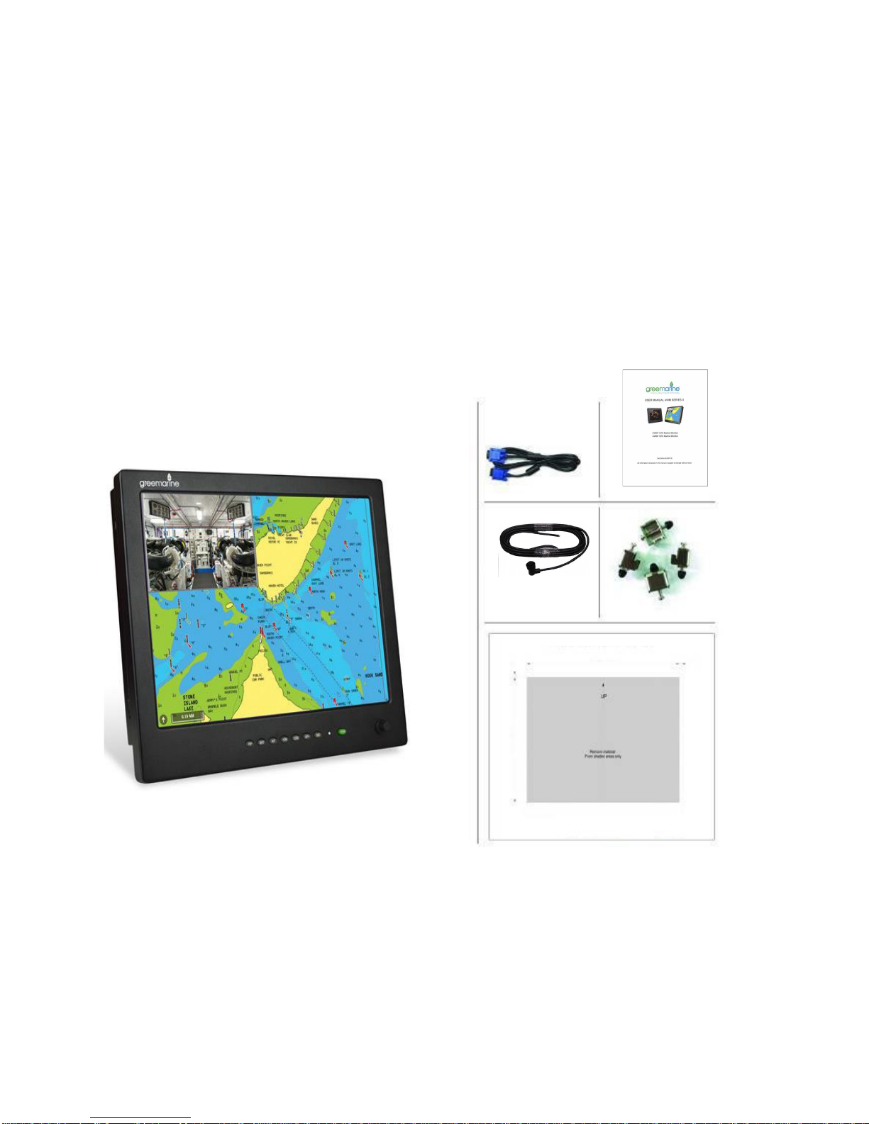
• Your AWM II display is sunlight viewable and visible in direct sunlight..
• If temperatures exceed the normal temperature operating range, the display could
overheat and begin to blackout due to the limitations of TFT LCD technology.
• In order to minimize the chances of a malfunction, the following precautions should be
taken during installation:
• The display should be installed in an area where there is proper and adequate
ventilation (min. 6 inches / 15cm clearance) . If it is possible to cool the area behind
the display, it will significantly reduce the risk of a malfunction.
• The display should be mounted at an angle to the sun. We do not recommend
mounting the unit in a flat plane, which increases the surface area exposed to the
sun and leads to increased heat absorption.
IMPORTANT: Your AWM Series II display is only waterproof from the front. To maintain
watertight integrity, the display must be flush mounted ensuring that the rear casing
is enclosed in a watertight enclosure.
The AWM Series II marine display is designed to be mounted in two configurations:
VESA75 / VESA100 MOUNT
Green Marine AWM Series II marine displays are compatible with VESA75 and VESA100
mounts. By installing the display with a compatable VESA mount the user can change
the displays angle to improve viewability. Before the display is mounted, power and signal source
should be connected and the display should be held at approximate mounting location to check viewing
angle for satisfactory picture quality.
8

Mounting holes built into the back surfaceof the display allow it to be mounted
by rear mount using VESA75 or VESA100 compatible mounts.
PANEL (Flush) MOUNT
For installation, there are four tapped mounting slots on both sides of the display
The mounting hardware packet is included with the product accessories in the
shipping box. This packet includes four (4) stainless steel threaded studs and
four (4) mounting lock nuts.
AWM Series II displays can be installed using the mounting lock nuts (supplied) in the
vertical keyways. Make sure that both brackets are installed in the same orientation.
Preparing the installation site
1. Select an installation site that has sufficient space behind it for cable connections
and ventilation.
2. Tape the supplied flush mount template in the required position.
3. Using a jigsaw, carefully remove the shaded portion of the template.
4. Using a suitable file, smooth the edges of the opening.
9
and on the top and bottom.

Installing the display
1. Carefully insert the display into the opening so the gasket on the backside
of the bezel edge lays flat against the front edge of the cut out.
IMPORTANT:The gasket must lay flat against the cut out edge to ensure watertight
integrity. Do not over tighten mounting screws.
2. Place the mounting bracket lugs into the keyways and move them to the rear, securing
the bracket to the display.
3. Using a suitable screwdriver, tighten the mounting bracket screws to secure the
monitor in position and compress the gasket.
NOTE: If console is thicker than 6/16 inch (10mm), caps on the ends of the screws may be
removed to provide additional clearance
10

4. Connect all cables as required - see “Rear connections” below.
Rear connections
The rear connectors are:
1. FUSE
2. Power Input
3. DVI-1 Input
4. DVI-2 Input
5. VGA-1 Input
6. VGA-2 Input
7. CVBS-1 Input (Composite Video) for AV input
8. CVBS-2 Input (Composite Video) for AV input
9. CVBS-3 Input (Composite Video) for AV input
10.RS232 Input
Planning the installation
Before you install your display, the following points should be considered:
• Power requirements.
• Display location and mounting options.
• Additional accessories, e.g. keyboard or speakers.
Power requirements
Your Sunlight Viewable display is designed to run on boat’s DC power systems rated at 12 V
or 24 V. Your AWM Series II display is equipped for a 9~36V DC wide range of power input.
The DC power system should be either:
• Negative grounded, with the negative battery terminal connected to the boat’s
ground,
• Floating, with neither battery terminal connected to the boat’s ground.
Grounding the display
It is important that an effective radio frequency (RF) ground is connected to the display.
You can ground the display by connecting
the ground wire (gray) of the power input
cable to the grounding screw on the back of the display located near the power connector
the nearest ground point of the boat's RF ground system on the other end.
on the display end, and
11
1 2 3 4 5 6 7 8 9 10

Display location and mounting options
Your display can be mounted using the flush mounting clamps supplied. Green Marine
recommends that you power the unit and select a suitable mounting location prior to
installing the display.
When planning the display location, the following points should be considered to ensure
safe, comfortable, and reliable operation:
• Convenience- the mounting location should be easily accessible to allow operation of
the front control buttons and should enable easy viewing of the display.
Power connections
The power connection to the display should be made at either the output of the battery
isolator switch, or at a DC power distribution panel. Green Marine recommends that power is
fed directly to the display via its own dedicated cable system and MUST be protected by
a thermal circuit breaker or fuse fitted close to the power connection. If you do not
have a thermal circuit breaker or fuse in your power circuit, you MUST fit an in-line
breaker or fuse to the positive (red) lead of the power cable.
• Installation angle- the AWM II display should be mounted at
an angle. Mounting it in a flat
plane is not recommended due to increased heat absorption.
• Viewing angle - this LCD has been chosen to give the very best performance, including
viewing angle. However, the contrast and colors seen on all LCD displays vary slightly
with viewing angle.
• Environment - to prevent overheating, do not restrict airflow at the rear of the
display. If the space behind the display is air conditioned or cooled by a fan, it will help in
keeping the unit’s temperature down when mounted in direct sunlight.
FAILURE TO ADEQUATELY VENTILATE THE UNIT COULD INVALIDATE YOUR WARRANTY.
The display should be protected from physical damage and excessive vibration. Although
the display is waterproof from the front when installed correctly, it is good practice
to mount it in a protected area away from prolonged and direct exposure to rain and salt
spray. DO NOT mount the display near a heat source.
Power connector
Grounding screw
angle for satisfactory
should be connected
Before the display is mounted, power and signal source
and display should be held at approximate mounting location to check viewing
picture quality.
12

Typical Installation Diagram
Remarks: The real installation diagram above is only for reference and will differ
for different kinds of applications.
13

4.0 OSD OPERATIONS
Introduction
AWM Series II displays can be controlled using the On Screen Display
(OSD) menu and/or the 8 buttons on the front bezel of the unit.
The OSD menu enables you to change the way in which your display is set up and is
accessed using the “OSD” button.
Using the buttons
Each of the 8 buttons on the front bezel of your display has a control function.
The “OSD” button and the down and up arrow buttons have miltiple functions.
POWER
Power Button On
To power your display ON, press the power button one time. There is a few seconds
delay before the display turns on.This delay is part of the displays protection against
any surge voltage from the engine.
Power Button Off
To power your display OFF, press the power button again. The same delay occurs
before powering down.
14

BRIGHTNESS Button
The BRIGHTNESS button is only a backup function in case the VR BRIGHTNESS knob fails.
Then use arrow buttons to change ''VR'' to ''BRILL'' and exit OSD.
After you release the “BRIGHTNESS” key around 5 seconds, the
brightness bar will disappear.
If the VR BRIGHTNESS knob fails to function, you can enable the brightness
button by pressing the ''OSD'' button, selecting ''OSD'', selecting ''Brightness''
VR BRIGHTNESS Knob
Your AWM Series II display is shipped with VR BRIGHTNESS knob function enabled as standard.
When you rotate the VR knob, the VR BRIGHTNESS status bar below will appear on screen.
(dimming range is from 1~50):
When you enter “NIGHT MODE” (see below)
turning the VR BRIGHTNESS knob will always take over the brightness function again.
Any modified or changed parameter setting will be automatically saved if you power off
or Exit the BRIGHTNESS status bar.
With "BRILL" enabled, you can now press the BRIGHTNESS button and the brightness
bar above will appear. The display brightness can now be controlled with down and up
The VR BRIGHTNESS knob always supersedes any other brightness setting.
arrow buttons.
15

NIGHT MODE Button
When you press the “NIT” button,the display will dim directly to 0.5 nit.
Pressing the button a second time dims the display to “black.”The button can now be used to
toggle back and forth between .5 nits and black for night viewing. Turning the VR Brightness
Knob will over ride NIGHT MODE and return the knob to brightness control.
Any modified or changed parameter setting will be automatically saved if you power off
or Exit the NIGHT MODE.
DOWN UP ARROW Buttons
The ARROW buttons work as navigation buttons to move the highlight cursor to the desired
The “UP” (right) arrow button can be used to move the hightlight cursor “Up”.
SIGNAL INPUT Button
When you press the “SIG” button, the screen below will pop up on the display:
You can now press the “DN” arrow button to move the highlight cursor ”Down” and
and the “UP” arrow button to move the highlight cursor “Up”.
If you release the “Arrow” buttons for 5 seconds without any action, the INPUT
SELECTION screen will be closed and it will remain at the item which you selected.
Any modified or changed parameter setting will be automatically saved if you power off.
selection. The “DN” (left) arrow button can be used to move the hightlight cursor “Down”.
16

1. Default main screen shows at RGB1 & RGB2ÆPress “PIP” button ÆFigure 1
2. Default main screen stays at DVI1 & DVI2ÆPress “PIP” button ÆFigure 2
3. Default main screen stays at VIDEO 1ÆPress “PIP” button ÆFigure 3_1
4. Default main screen stays at VIDEO 2ÆPress “PIP” button ÆFigure 3_2
5. Default main screen stays at VIDEO 3ÆPress “PIP” button ÆFigure 3_3
PIPFunctionSupportingTable
Sub
Main
RGB1 RGB2 DVI1 DVI2 VIDEO1 VIDEO2 VIDEO3 !
RGB1 !! OK OK OK OK OK Figure1
RGB2 !! OK OK OK OK OK Figure1
DVI1 OK OK ! OK OK OK Figure2
DVI2 OK OK !OK OK OK Figure2
VIDEO1 OK OK OK OK ! OK OK Figure3_1
VIDEO2 OK OK OK OK OK ! OK Figure3_2
VIDEO3 OK OK OK OK OK OK ! Figure3_3
Figure1 Figure2
Figure3_1 Figure3_2 Figure3_3
PIP Button
17

PIP (1-10) Picture Size
You can choose PIP size scaling from 1~10 times and PAP1 (4:3 aspect ratio) or PAP2 (side
by side for half full screen). For re-sizing screen, see PIP sub menu setting screen (page 24)
PIP Picture Placement
When the PIP screen is activated in the main display window, the “DN” and “UP” arrow
buttons may be used to move the PIP window around the display screen. The arrow
buttons will move the PIP window horizontal until it can move no further, then the PIP
window will start moving vertical. In this way the PIP window can be possitioned anywhere
on the main display screen.
ll be automatically saved if you power off.Any modified or changed parameter setting wi
selection screen will be closed and it will remain at the item which you selected.
nds without any action, the INPUTIf you release the “Arrow” buttons for 5 seco
and the “UP” arrow button to move the highlight cursor “Up”.
You can now press the “DN” arrow button to move the highlight cursor ”Down” and
18
This manual suits for next models
2
Table of contents