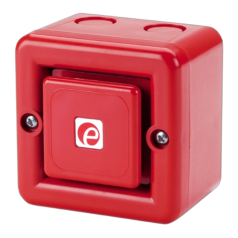
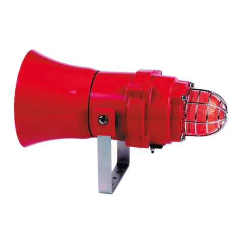
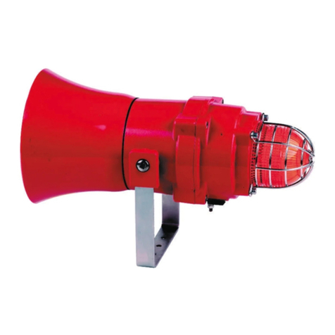
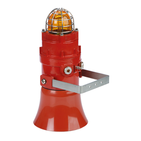
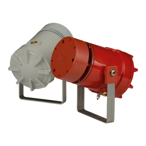
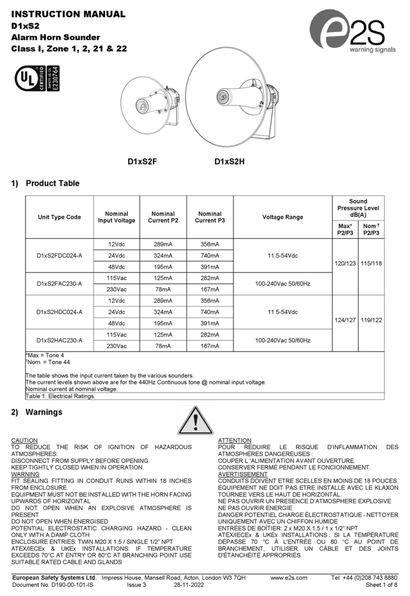
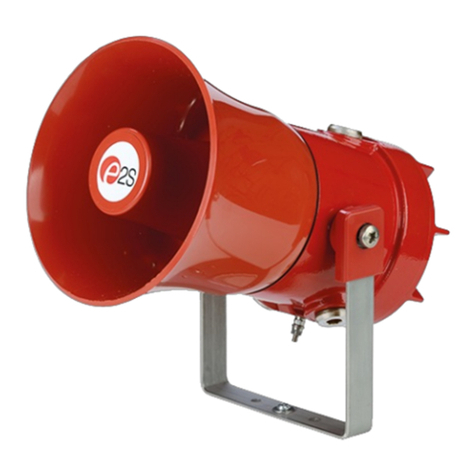
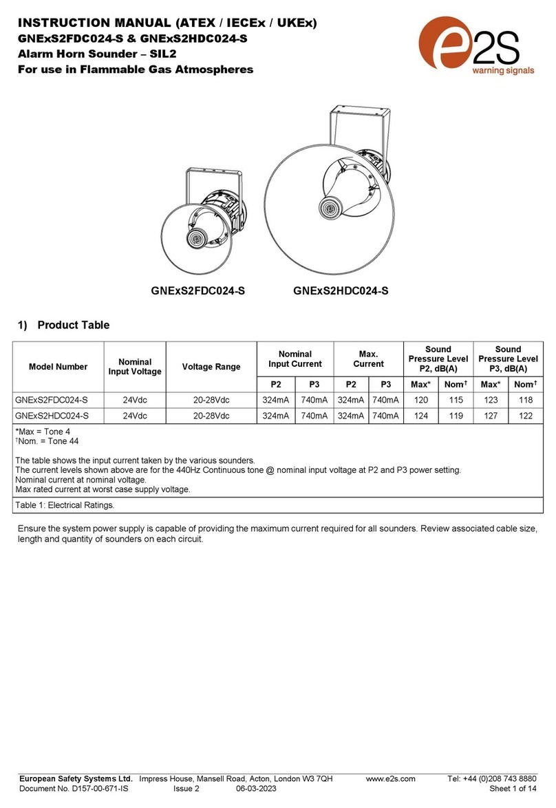
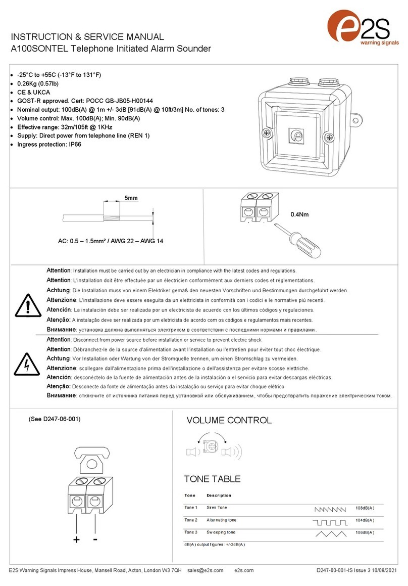
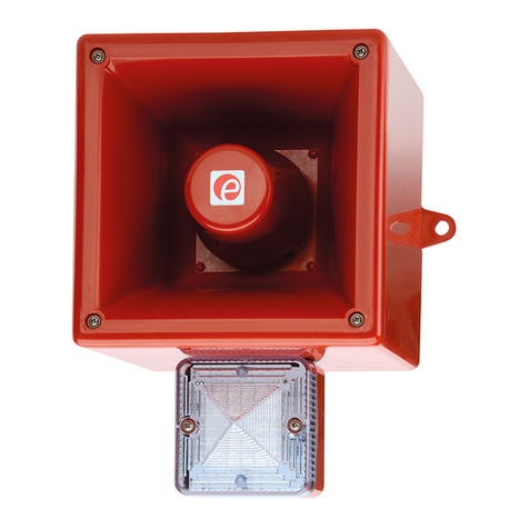
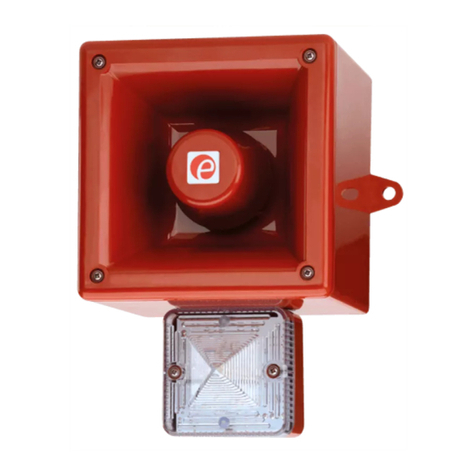
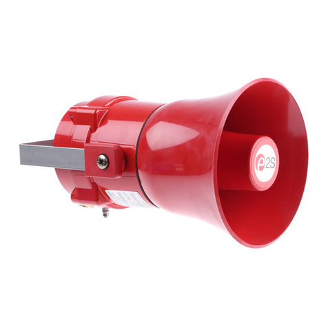
E2S BEXCS11005D230AC-AM User manual

_______________________________________________________________________________________________________________________________
EuropeanSafetySystemsLtd. Impress House, MansellRoad, Acton, London W37QHsales@e2s.com Tel: +44 (0)208 743 8880
www.e2s.com Fax: +44 (0)208 740 4200
DocumentNo. IS2441-PIssue C04-07-02 Sheet 1of6
INSTRUCTIONMANUAL(ATEX)
BExCS110-05D
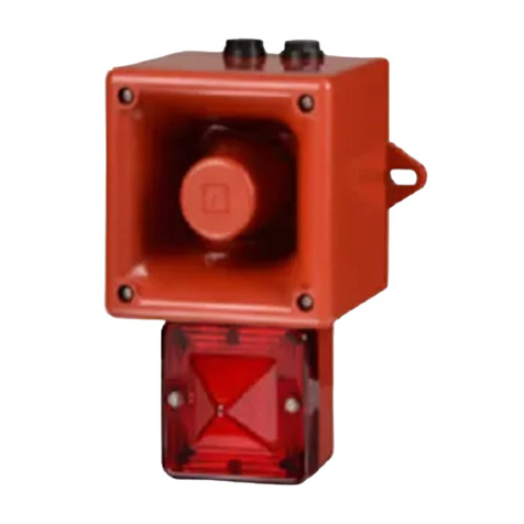
FlameproofCombined Sounder/Beacon
1)Introduction
TheBExCS110-05Disasecondgenerationflameproof
combinedsounder/beaconwhichiscertifiedtothe
European StandardsEN50014:1997 andEN50018:2000
andmeetstherequirementsoftheATEX directive94/9/EC.
Thesoundersectionproducesloudaudiowarningsignals
andthebeaconsectionproducesasynchronisedvisual
warningsignal.Theunitcan be usedinhazardousareas
wherepotentiallyflammableatmospheresmaybepresent.
Thirty-twodifferentfirststage audioalarmsoundscan be
selected byinternalswitches, andeachonecan be externally
changed toasecondorthirdstagealarmsound(seetone
tableon Page5).Thesounderproducesoutputlevelsinthe
110dB(A)range andthebeaconproducesan outputlevelof
5joules.Theunitcanbe usedinZone1andZone2areas
withgasesingroupsIIAandIIBandwithTemperature
ClassificationsofT1, T2, T3andT4.
2)Marking
All unitshavearatinglabel,whichcarriesthefollowing
important information:-
UnitType No. BExCS110-05D
Input Voltage: DC Units12Vor24Vor48V
ACUnits230Vor115V
Code: EExdIIBT4(Tamb. –50 to+55°C)
CertificateNo. KEMA01ATEX2223
Warnings:DONOTOPENWHENANEXPLOSIVE
GAS ATMOSPHEREISPRESENT
COVERBOLTSCLASS A4-80
USE HEATRESISTINGCABLES AND
CABLEGLANDS(Rated 95ºC)AT
AMB. TEMPERATURES OVER40ºC
YearofConstruction/
SerialNo. i.e. 02 / 1CS21000001
3) TypeApprovalStandards
TheunitshaveanECType examinationcertificateissuedby
KEMAandhavebeenapproved tothefollowingstandards:-
EN50014: 1997GeneralRequirements
EN50018: 2000FlameproofEnclosure‘d’
4) Installation Requirements
Theunitmustbe installed inaccordancewiththelatest
issuesoftherelevantpartsoftheBSEN60079
specificationsortheequivalentIECspecifications–
Selection,Installationandmaintenanceofelectrical
apparatusforuseinpotentiallyexplosiveatmospheres(other
thanminingapplicationsorexplosiveprocessingand
manufacture):-
BS EN60079-14 : 1997 ElectricalInstallationsinHazardous
Areas(otherthan mines)
BS EN60079-10 : 1996 Classification of HazardousAreas
Theinstallationoftheunitmustalsobeinaccordancewith
anylocalcodesthatmayapplyandshouldonlybe carried
outbyacompetentelectricalengineerwhohasthe
necessarytraining.
5) Zones,Gas Group, Categoryand Temperature
Classification
TheBExCS110-05DunithasbeencertifiedEExdIIBT4
(Tamb.–50 to+55ºC).Thismeansthattheunitscan be
installed inlocationswiththefollowingconditions:-
Area Classification:
Zone1 Explosivegasairmixturelikelytooccurin
normaloperation.
Zone2 Explosivegasairmixturenotlikelytooccur,
andifit does, it will onlyexist forashort time.
GasGroupings:
GroupIIA Propane
GroupIIB Ethylene
EquipmentCategory: 2G
TemperatureClassification:
T1 400oC
T2 300oC
T3 200oC
T4 135oC
AmbientTemperatureRange:
-50°Cto+55°C
0344
II 2G
Epsilonx:
GasGroupand
Category:
CEMarking:
NotifiedBodyNo.
ImportantNotice: The BExCS110-05Disnotforsale, re-sale, installation, orusewithin
the United Statesof Americaasasole, multiple, integrated, orincorporated unit.

_______________________________________________________________________________________________________________________________
EuropeanSafetySystemsLtd. Impress House, MansellRoad, Acton, London W37QHsales@e2s.com Tel: +44 (0)208 743 8880
www.e2s.com Fax: +44 (0)208 740 4200
DocumentNo. IS2441-PIssue C04-07-02 Sheet 2of6
6) Location andMounting
Thelocationoftheunitshouldbemadewithdueregardto
theareaoverwhichboththesounderandbeaconwarning
signalmustbeaudibleandvisible.Theunitshouldonlybe
fixed toservicesthat cancarrytheweight oftheunit.
Theunitshouldbesecurelyboltedtoasuitablesurfaceusing
the7mmdiameterboltholesinthestainlesssteelUshaped
mountingbracket(see figure1).Theanglecan thenbe
adjusted inthedirectionsuchthatitswarningsignalscan be
bothheardandseen.Thiscan be achievedbylooseningthe
twolarge bracketscrewsintheside oftheunit, whichallow
adjustmentinstepsof 18°.Oncompletionoftheinstallation
thetwolarge bracketadjustmentscrewsonthesideofthe
unitmustbe fullytightened toensurethattheunitcannot
moveinservice.
7) SafetyWarning (ElectrostaticHazard)
TheacoustichornsectionismadeofABSPlastic,therefore
toavoidapossibleELECTROSTACTICCHARGEtheunit
must onlybe cleanedwithadampcloth.
8) Access to theFlameproofEnclosure
Inordertoconnecttheelectricalsupplycablestothe unititis
necessarytoremovethebeaconsectiontogainaccess to
theflameproof chamber.ToachievethisremovethefourM6
hexagonsocketheadscrews(see figure2)andwithdrawthe
beaconsectiontakingextremecarenottodamagethe
flameproofjointsintheprocess.
Notethefour M6screwsareClass A4-80 stainlesssteel
andonlyscrewsofthiscategorycanbeusedonthese
units. Itisthereforeimportantthatthesescrewsandtheir
springwashersarekept inasafeplaceduringinstallation.
Oncompletionofthecablewiringinstallationtheflameproof
jointsshouldbe inspected toensurethattheyareclean and
thattheyhavenotbeendamaged duringinstallation.Also
checkthattheearthbondingwirebetweenthetwocasting
sectionsissecureandthe‘O’ringsealisinplace.When
replacingthebeaconsectioncasting,ensurethatitissquare
withthesoundersectionchambercastingbeforeinserting.
Carefullypushthebeaconsectioninplaceallowingtimefort
theairtobe expelled. Onlyafterthebeaconsectioncastingis
fullyinplaceshouldthefourM6Stainless SteelA4-80cover
boltsandtheirspringwasherbeinsertedandtightened
down.If thebeaconsectionjamswhileitisbeinginserted,
carefullyremoveit andtryagain.Neverusethecoverboltsto
forcethebeaconsectioncastingintoposition.
9) PowerSupplySelection
Itisimportantthatasuitablepowersupplyisusedtorun the
unit. Thepowersupplyselectedmusthavethe necessary
capacitytoprovide theinputcurrenttoall ofthe units
connectedtothesystemThesounderandbeaconsections
can bothbewired tothesamepowersupplyortodifferent
powersupplies
Thefollowingtableshowsthe inputcurrenttakenbythe
soundersectionandbeaconsectionofthevariousunits:-
UnitTypeInputSounderMax.
VoltageCurrentI/PVolts
BExCS110-05D24VDC 265mA30V
BExCS110-05D12VDC 195mA15V
BExCS110-05D48VDC 130mA58V
BExCS110-05D230VAC56mA264V
BExCS110-05D115VAC110mA126V
UnitTypeInputBeaconMax.
VoltageCurrentI/PVolts
BExCS110-05D24VDC 300mA30V
BExCS110-05D12VDC 750mA15V
BExCS110-05D48VDC 180mA58V
BExCS110-05D230VAC55mA264V
BExCS110-05D115VAC140mA126V
Theabovetablealsoshowsthe maximumvoltagesatwhich
theunitscan be operated.
SounderSection
Theinput currenttothesoundersectionwill varyaccordingto
thevoltage input levelandthefrequencyofthetoneselected.
Thecurrentlevelsshownaboveareforthe440Hz
Continuoustone@nominalinputvoltage.The24Vand48V
DC unitsandthe230VAC,115VACunitshaveaswitching
voltage regulatorcircuitandthereforetheinputcurrentlevel
will decreaseslightlyastheinputvoltage inincreasedand
will increaseslightlyastheinputvoltage isreduced.The12V
unitsdo nothaveavoltage regulatorandthereforetheirinput
current willincreasewhentheinputvoltage isincreased.
S/SMounting
Bracket
Sounder
Section
Flashdome
Guard
PlasticAcousticHorn
Pleasesee SafetyWarning
InSection 7of thismanual
Fig1
Beacon
Section
4off CoverScrews ExternalEarth
Terminal
Fig2

_______________________________________________________________________________________________________________________________
EuropeanSafetySystemsLtd. Impress House, MansellRoad, Acton, London W37QHsales@e2s.com Tel: +44 (0)208 743 8880
www.e2s.com Fax: +44 (0)208 740 4200
DocumentNo. IS2441-PIssue C04-07-02 Sheet 3of6
BeaconSection
Theinputcurrenttothebeaconsectionwill varyaccordingto
thevoltage inputlevel.Thecurrentlevelsshownaboveare
fornominalinputvoltage.The12V,24Vand48VDCunits
haveaconvertercircuitandthereforetheinputcurrentlevel
will decreaseslightlyastheinputvoltage inincreasedand
will increaseslightlyastheinput voltage isreduced.
10) CableSelection
Whenselectingthecablesizeconsiderationmustbegivento
theinputcurrentthateachunitdraws(see tableabove),the
numberofunitsonthelineandthelengthofthecableruns.
Thecablesizeselectedmusthavethenecessarycapacityto
provide theinputcurrenttoall oftheunitsconnectedtothe
line.
SAFETYWARNING: Iftheunitisusedathighambient
temperatures,i.e.over+40ºC,thenthecableentry
temperaturemayexceed +70ºCandthereforesuitableheat
resistingcablesmustbeused,witharated service
temperatureofat least 95ºC.
11) Earthing
BothACandDC unitsmustbeconnectedtoagood quality
earth.Theunitsareprovidedwithinternalandexternal
earthingterminals,whichareboth,locatedonthe beacon
sectionoftheunit (see figures2and3).
Whenusingtheexternalearthterminalacablecrimplug
mustbe used.Thecablelugshouldbe locatedbetweenthe
twoM5stainless steelflatwashers.TheM5stainlesssteel
springwashermustbe fixed betweentheouterflatwasher
andtheM5stainless steelnuttoensurethatthecablelugis
secured against looseningandtwisting.
Theinternalearthbondingwireensuresthatagoodquality
earthismaintained betweenthesoundersectioncastingand
thebeaconsectioncasting.
12) CableGlands
TheBExCS110-05Dunithasdualcableglandentrieswhich
haveanM20 x1.5entrythreadasstandard.Onlycable
glandsapprovedforEx‘d’applicationscan be used,which
mustbe suitableforthetype ofcablebeingusedandalso
meettherequirementsoftheEx‘d’flameproofinstallation
standardBS EN60079-14: 1997.
SAFETYWARNING: Iftheunitisusedathighambient
temperatures,i.e.over+40ºC,thenthecableentry
temperaturemayexceed +70ºCandthereforesuitableheat
resistingcableglandsmustbe used,witharated service
temperatureofat least 95ºC.
IfahighIP(IngressProtection)ratingisrequired thena
suitablesealingwashermust befitted underthecablegland.
Whenonlyonecableentryisusedtheotheronemustbe
closedwithanEx‘d’flameproofblankingplug, whichmust be
suitablyapprovedfortheinstallationrequirements.
13) CableConnections
ThecombinedsounderbeaconunitBExCS110-05Dhas
separateprinted circuitboardsinthesounderandbeacon
sections.Theterminalsforthesounderareontheprinted
circuitboardinthesoundersectionandtheterminalsforthe
beaconareontheprinted circuitboardinthebeaconsection
(seefigures4&5and6&7).Seesection8ofthismanualfor
accesstotheenclosureandthewiringdiagramsattheendof
thismanual.
Thesounderandbeaconsectionscan be wiredtothesame
inputsupplysothattheyoperatesimultaneouslyortheycan
be wiredtoseparateinputsuppliessotheycan beoperated
independently(seediagramsofpages5and6ofthis
manual).If thesounderandbeaconsectionsareconnected
tothesameinputsupply,theincomingcablesshouldbe
connected totheinput terminalsonthebeaconboardandthe
twoconnectingwires,thataresuppliedwiththeunit,should
beusedtolinkthesupplyfromtheinterconnectingterminals
onthebeaconboarddowntothesupplyterminalsonthe
sounderboard.
SOUNDERSECTIONCONECTIONS
OntheACunitsatwo-wayterminalblockisprovidedforthe
liveandneutralmainssupplywiresandathree wayterminal
blockisprovidedforlinkingthesecond andthirdstages,(see
figure7).OntheDC unitsafourwayterminalblockis
providedfor+veand–vesupplyinput andsecondandthird
stage modesofoperation, (seefigure6).
Asinglewirewithacross sectionalareaofupto4mm²can
be connectedtoeachterminalwayorifan inputandoutput
wireisrequired two2.5mm²wirescan be connected toeach
terminalway.Whenconnectingwirestotheterminalsgreat
careshouldbetakentodress thewiresothatwhenthe
beaconsectionisinserted intothechamberthewiresdo not
exertexcess pressureontheterminalblocks.Thisis
particularlyimportantwhenusingcableswithlarge cross
sectionalareassuchas2.5mm²andabove.If thesounderis
wired tothesamepowersupplyasthebeaconalwaysuse
theflexibleinterconnectingwiresprovided.
BEACONSECTIONCONNECTIONS
Thecableconnectionsaremade intotheterminalblockson
theelectronicpcbassemblylocatedinthebeaconsection
enclosure.Afour-wayterminalblockisprovidedonbothAC
andDC beacons.Thereforetherearetwoliveterminalsand
twoneutralterminalsfortheinputandoutputwiringonAC
units.OntheDC unitstherearetwo+veterminalsandtwo-
veterminalsfortheinput andoutputwiring.
Wireshavingacross sectionalarea ofupto4mm²can be
connected toeachterminalway.Whenconnectingwiresto
Inte
rnalBonding WireTerminal
InternalEarthTerminal
2off M20
CableEntries
Figure3
_______________________________________________________________________________________________________________________________
EuropeanSafetySystemsLtd. Impress House, MansellRoad, Acton, London W37QHsales@e2s.com Tel: +44 (0)208 743 8880
www.e2s.com Fax: +44 (0)208 740 4200
DocumentNo. IS2441-PIssue C04-07-02 Sheet 4of6
theterminalsgreat careshouldbe takentodress thewiresso
thatwiresdo notexertexcesspressureontheterminal
blocks.Thisisparticularlyimportantwhenusingcableswith
large crosssectionalareassuchas2.5mm²andabove.
14) ToneSelection and 2nd and 3rd StageAlarms
TheBExCS110-05Dsoundersectionhas32differenttones
thatcan be selectedforthefirststagealarm.Thesounders
can thenbe switched tosoundsecondandthirdstage alarm
tones. ThetonesareselectedbyoperationofaDIPswitchon
thesounderpcbforbothDCandACunits.Thetonetableon
page fiveshowstheswitchpositionsforthe32 tonesand
whichtonesareavailableforthesecondandthirdstages. To
operatethesounderonstage onesimplyconnectthesupply
voltage tothenormalsupplyterminals(+veand–veforDC
units, LandNforACunits).
Theoperationofthesecondandthirdstagesisdifferentfor
DC andACunits.
DC UnitsSecondandThirdStageToneSelection
TheBExCS110-05DDC soundersectionhasthefacilityto
useeither+veor–veswitchingtochange thetonetothe
secondandthirdstages.For–veswitchingconnectthetwo
headersonthepcbtotheleft-hand(marked –ve)andcentre
pins.For+veswitchingconnecttheheaderstotherighthand
(marked +ve)andthecentrepins.Tochange tothesecond
stage tone, connecteithera-veor+vesupplylinetoterminal
S2,dependingonwhichswitchingmodeisbeingusedwhile
maintainingthedcsupplytothe+veand–veterminals.
Similarlyforthethirdstage tone,connecta-veor+vesupply
linetoterminalS3.ThesupplytotheS3terminalwill
automaticallyoverride asupplytotheS2terminal.
ACUnitsSecondandThirdStageToneSelection
Toselectthesecondandthirdstage tonesonthe
BExCS110-05DACsoundersection,theCommon(C)
terminalonthethree wayterminalblockonthepcbis
connected totheS2terminalforthesecondstage toneand
theS3terminalforthethirdstage tone.
15) Volume Control
TheBExCS110-05Dsoundersection,withtheexceptionof
12VDCunits,hasavolumecontroltoadjustthe outputlevel.
Tosettherequired outputlevel,adjustthepotentiometeron
thepcb.Formaximumoutputlevelthepotentiometershould
beset tothefullyclockwiseposition.
Figure7
Figure6
BExCS110
-
05DDC SounderSection
BExCS110-05DACSounderSection
VolumeControl
DIPSwitch
DIPSwitch
VolumeControl
DC Input
Terminals
Stage Headers
Stage Terminals
ACInput
Terminals
S2
S3
-
+
S2
S3
C
N
L
L
L
N
N
Figure4
ACInput
Terminals
Interconnecting Terminalsto
sounderpcb(simultaneous
mode of operation)
BExCS110-05DACBeaconSection
Flip / Flop
Pin Header
DC Input
Terminals
Figure5
-
-
+
+
Flip / Flop
Pin Header
BExCS110
-
05DDC BeaconSection
Interconnecting Terminalsto
sounderpcb(simultaneous
mode of operation)

_______________________________________________________________________________________________________________________________
EuropeanSafetySystemsLtd. Impress House, MansellRoad, Acton, London W37QHsales@e2s.com Tel: +44 (0)208 743 8880
www.e2s.com Fax: +44 (0)208 740 4200
DocumentNo. IS2441-PIssue C04-07-02 Sheet 5of6
16) End ofLineMonitoring (DC Units)
OnBExCS110-05DDCunits,dcreverseline monitoringcan
beusedifrequired.All DC unitshaveablockingdiodefitted
intheirsupplyinputlinesonboththesoundersectionandthe
beaconsection.Anendof linemonitoringdiodeoran endof
linemonitoringresistorcan be connectedacrossthe+veand
–veterminals. If an end of lineresistorisuseditmusthavea
minimumresistancevalueof3k3ohmsandaminimum
wattage of0.5wattsoraminimumresistancevalueof500
ohmsandamin.wattage of2watts.If thesounderand
beaconsectionsarewired toseparatepowersuppliesthen
an endoflinemonitoringcomponentcan beusedineach
section.
17) Synchronised Operation
All BExCS110-05Dunitsthatareconnected tothesame
supplylinewill haveasynchronized soundoutputanda
synchronisedflashrateatoneflasheverysecond. Toensure
thattheunitswill be synchronisedcheckthatthepinheader
isnotfitted,i.e.thetwoheaderpinsarenotshorted together
(seeFigures4and5).
18) Flip / Flop Operation
Twounitscan be mounted closetoeachothertoformaflip-
flopoperation,wherethebeaconswill flashalternately.To
achievethismodeofoperation,fitapinheadertotheflip-
flopheaderpinsontheelectronics board,i.e.thetwoheader
pinsareshortedtogether,(seefigures4and5)onone of the
twobeacons.Thefirstflashonthebeaconthathasthe
headerfittedwill be delayedby½second.Thetwobeacons
will thenflashalternatelyevery½asecond.
TONESELECTIONTABLE
ToneSelection
DIPSwitch
Settings
StageSelection
Stage1 FrequencyDescription 12345
Stage2 Stage3
1 Continuous1000Hz
Toxicgasalarm 00000 Tone31 Tone11
2 Alternating800/1000Hzat0.25s
intervals 10000 Tone17 Tone5
3 SlowWhoop 500/1200Hzat0.3Hz
with0.5sgaprepeated 01000 Tone2 Tone5
4 Sweeping800/1000 at1Hz 11000 Tone6 Tone5
5 Continuousat2400Hz 00100 Tone3 Tone27
6 Sweeping2400/2900Hzat7Hz 10100 Tone7 Tone5
7 Sweeping2400/2900Hzat1Hz 01100 Tone10 Tone5
8 Siren500/1200/500Hzat0.3Hz 11100 Tone2 Tone5
9 Sawtooth1200/500Hzat1Hz 00010 Tone15 Tone2
10 Alternating2400/2900Hzat2Hz 10010 Tone7 Tone5
11 Intermittent1000Hzat0.5Hz
Generalalarm 01010 Tone31 Tone1
12 Alternating800/1000Hzat0.875Hz 11010 Tone4 Tone5
13 Intermittent2400Hzat1Hz 00110 Tone15 Tone5
14 Intermittent800Hz0.25son 1soff 10110 Tone4 Tone5
15 Continuousat800Hz 01110 Tone2 Tone5
16 Intermittent660Hz150mSon,
150mSoff 11110 Tone18 Tone5
17 Alternating544Hz
(100mS)/440Hz(400mS) 00001 Tone2 Tone27
18 Intermittent660Hz1.8son, 1.8soff 10001 Tone2 Tone5
19 1400Hzto1600Hzsweepupover
1s-1600Hzto1400Hzsweepdown
over0.5s
01001 Tone2 Tone5
20 Continuous660Hz11001 Tone2 Tone5
21 Alternating554/440Hzat1Hz 00101 Tone2 Tone5
22 Intermittent554Hzat0.875Hz 10101 Tone2 Tone5
23 800Hzpulsingat2Hz 01101 Tone6 Tone5
24 Sweeping800/1000Hzat50Hz 11101 Tone29 Tone5
25 Sweeping2400/2900Hzat50Hz 00011 Tone29 Tone5
26 Simulatedbell sound 10011 Tone2 Tone1
27 Continuous554Hz 01011 Tone26 Tone5
28 Continuous440Hz 11011 Tone2 Tone5
29 Sweeping800/1000Hzat7Hz 00111 Tone7 Tone5
30 420Hzrepeating0.625son, 0.625s
off Australianalertsignal 10111 Tone32 Tone5
31 1200/500Hzat1Hz
Preparetoabandonplatform 01111 Tone11 Tone1
32 Sweeping500/1200Hz3.75son,
0.25soff 15Hz 11111 Tone26 Tone1
Unit No.2
+
+
-
S2
S3
-
Sounder
PCB
+-S2 S3
UnitNo. 1
Beacon
PCB
+- +-
Beacon
PCB Beacon
PCB
+-
Sounder
PCB
+-S2 S3
Sounder
PCB
+-S2 S3
Unit No.3
BExCS110
-
05DDC CombinedSounderUnit
BeaconandSounderWiredforIndependent Operation
NOTE
Eitherthe+veorthe-vewiremay
bemadecommontoboththe
sounderand thebeacontoreduce
thenumberof coresinthecable.

_______________________________________________________________________________________________________________________________
EuropeanSafetySystemsLtd. Impress House, MansellRoad, Acton, London W37QHsales@e2s.com Tel: +44 (0)208 743 8880
www.e2s.com Fax: +44 (0)208 740 4200
DocumentNo. IS2441-PIssue C04-07-02 Sheet 6of6
UnitNo.2
+
-
Sounder
PCB
+-S2 S3
UnitNo. 1
Beacon
PCB
+- -
+-
+-
Beacon
PCB ++-
Beacon
PCB
+-S2 S3
Sounder
PCB +-S2 S3
Sounder
PCB
-
+
Unit No.3
S2
S3
Unit No.2
L
C
N
L
N
LNC S2 S3
Sounder
PCB
UnitNo. 1
LN
Beacon
PCB LN
Beacon
PCB LN
Beacon
PCB
LNC S2 S3
Sounder
PCB
LNC S2 S3
Sounder
PCB
UnitNo. 3
UnitNo.2
C
N
S3
S2
L
Sounder
PCB
Unit No.1
LNC S2 S3
Beacon
PCB
LN L
NLN
Beacon
PCB L
N
Beacon
PCB
LN
Sounder
PCB
LNC S2 S3 LNC S2 S3
L
N
Sounder
PCB
UnitNo.3
BExCS110
-
05DDC CombinedSounderUnit
BeaconandSounderWiredforSimultaneousOperation
BExCS110
-
05DACCombinedSounderUnit
BeaconandSounderWiredforIndependent Operation
BExCS110
-
05DACCombin
edSounderUnit
BeaconandSounderWiredforSimultaneousOperation
NOTE
EithertheLortheNwiremaybe
madecommontoboththesounder
and thebeacontoreducethe
numberof coresinthecable.
This manual suits for next models
3
Table of contents
Other E2S Marine Equipment manuals

E2S
E2S D1xS1RDC024-S User manual

E2S
E2S D1xC1 Series User manual

E2S
E2S A112N User manual

E2S
E2S SONF1DC024 X Y Series User manual

E2S
E2S E2xS1RDC024 Manual

E2S
E2S D2xB1LD2 User manual

E2S
E2S Minialert IS-mC1 User manual

E2S
E2S DL112H User manual

E2S
E2S AlertAlight AL112NXDC012 User manual

E2S
E2S AL121H Series User manual
Popular Marine Equipment manuals by other brands

APPLIED ACOUSTICS SYSTEMS
APPLIED ACOUSTICS SYSTEMS 3510 PAM Portable Operation manual

urmet domus
urmet domus 1033/426 quick start guide

Furuno
Furuno FMV-603 Operator's manual

Furuno
Furuno FA-170 installation manual

SurTec
SurTec Star-vox 22PSER001 manual

Raymarine
Raymarine autopilot ST4000+ Owner's handbook