Sailmon E4 User manual

Sailmon © 2019 15/06/2019
Installation Manual version 3.2.0
1
SAILMON
Installation Manual version 3.2.0
June 2019

Sailmon © 2019 15/06/2019
Installation Manual version 3.2.0
2
Contents
DISCLAIMER.....................................................................................................................................................4
COPYRIGHT ............................................................................................................................................................4
LIABILITY AND SAFETY WARNINGS .....................................................................................................................4
ABOUT THIS MANUAL......................................................................................................................................5
INTRODUCTION ...............................................................................................................................................6
SYSTEM INTRODUCTION............................................................................................................................................6
SAILMON SYSTEM EXAMPLE .......................................................................................................................................7
CHAPTER 1 PRODUCT OVERVIEW ....................................................................................................................7
1.1 FUNCTIONALITY.................................................................................................................................................7
1.2 INSTRUMENT INTEGRATION .................................................................................................................................8
1.3 SOFTWARE .......................................................................................................................................................8
1.4 CONNECTIVITY ..................................................................................................................................................8
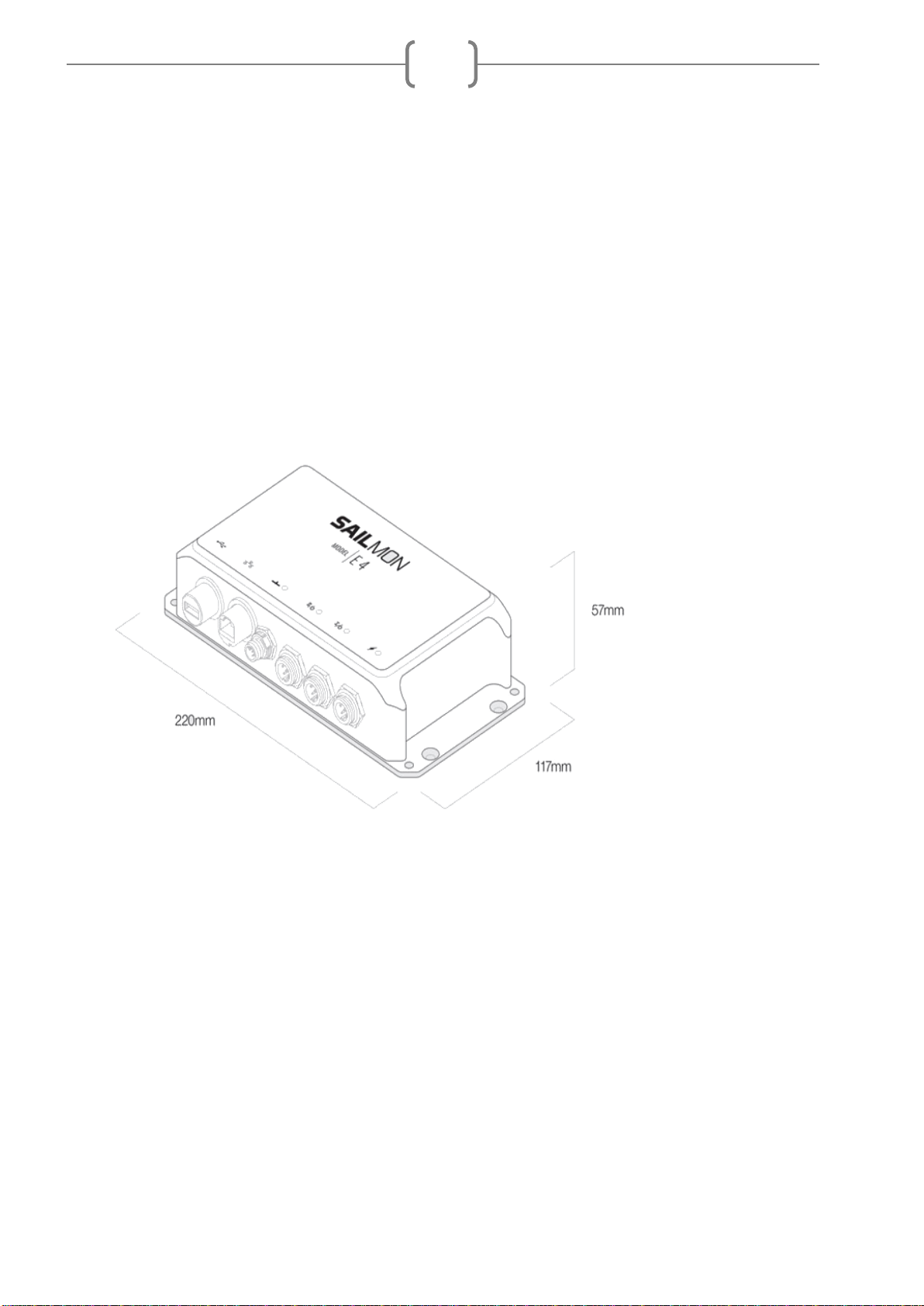
1.5 TECHNICAL SPECIFIACTIONS E4.............................................................................................................................9
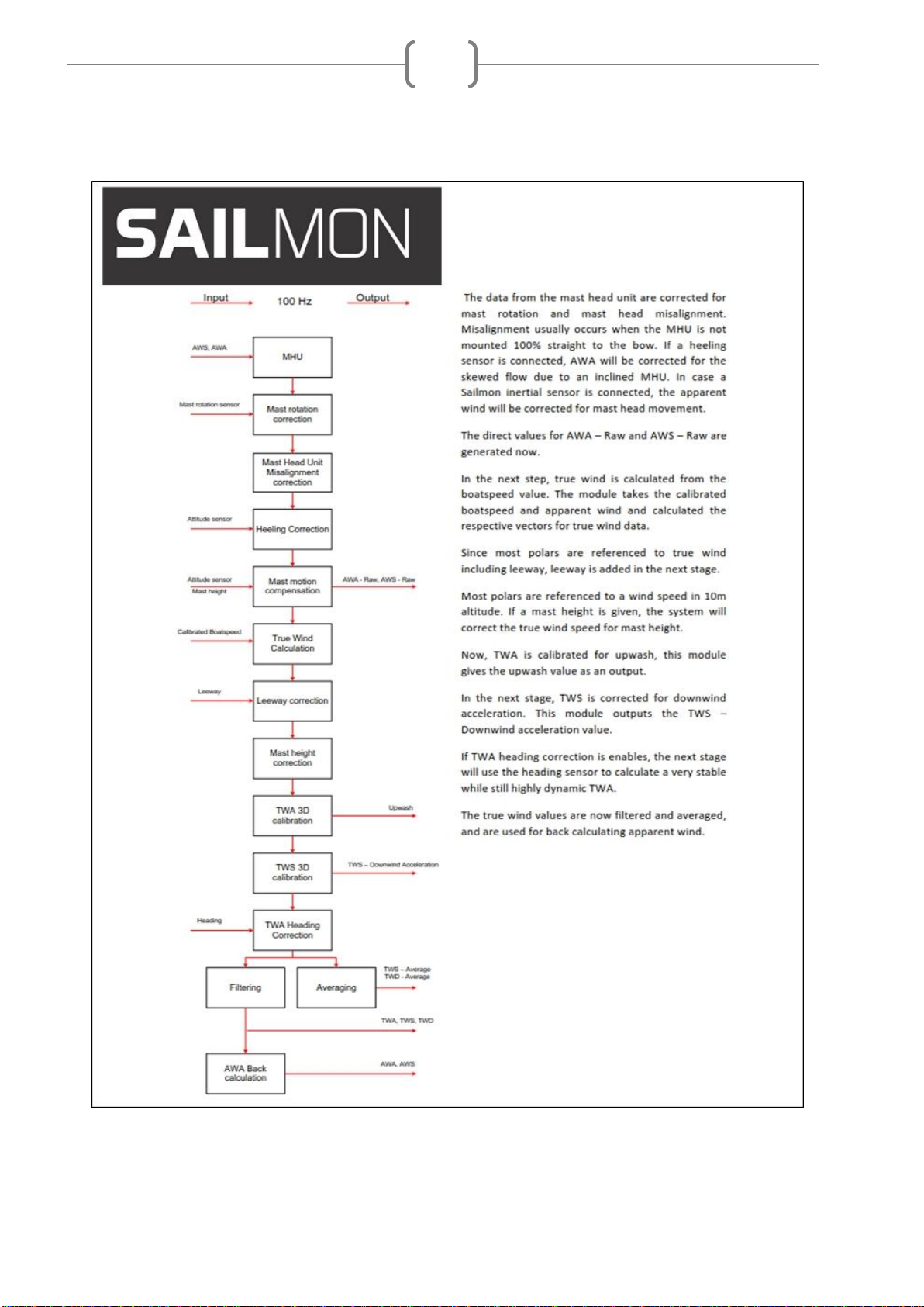
1.6 SYSTEM ARCHITECTURE.......................................................................................................................................9
CHAPTER 2 INSTALLATION ............................................................................................................................11
2.1 NMEA2000..................................................................................................................................................11
2.2 E4 INSTALLATION.............................................................................................................................................12
2.2.1 E4 port connections.............................................................................................................................13
2.2.2 LED Status ...........................................................................................................................................13
2.2.3 Sensor connecting ...............................................................................................................................13
2.2.4 Protocols .............................................................................................................................................15
2.3 SAILMON COMPONENTS....................................................................................................................................15
2.3.1 Snet connector ....................................................................................................................................15
2.3.2 SAILethernet ........................................................................................................................................17
2.3.3 Recommended Fuse rating..................................................................................................................18
2.3.4 Windbox ..............................................................................................................................................19
2.3.5 LinearBox.............................................................................................................................................21
2.3.6 Loadcell Box ........................................................................................................................................23
CHAPTER 3 NETWORK INSTALLATION...........................................................................................................30
3.1 TO CONNECT THE THE E4 TO THE BOATNETWORK...................................................................................................30
3.1.1 Ethernet:..............................................................................................................................................30
3.1.2 Switch:.................................................................................................................................................30
3.1.3 Wireless /4G Router ...........................................................................................................................31
3.1.4 4G Router ............................................................................................................................................32
3.2 SAILMON NETWORK.........................................................................................................................................32
3.2.1 Overview .............................................................................................................................................32
3.2.2 Complex network installations ............................................................................................................33
3.2.3 UDP Traffic ..........................................................................................................................................33
CHAPTER 4 COMMISSIONING ........................................................................................................................35
4.1 IDENTIFYING SENSORS.......................................................................................................................................35
4.2 STANDARD SENSORS.........................................................................................................................................35
4.3 MISCELLANEOUS SENSORS.................................................................................................................................36
CHAPTER 5 SOFTWARE ..................................................................................................................................37

Sailmon © 2019 15/06/2019
Installation Manual version 3.2.0
3
5.1 SOFTWARE DOWNLOAD ....................................................................................................................................37
5.2 MINIMUM SYSTEM REQUIREMENTS.....................................................................................................................37
5.3 USING SOFTWARE TO CONNECT TO E4.................................................................................................................37
CHAPTER 6 DISPLAYS .....................................................................................................................................38
6.1 PRODUCT OVERVIEW ........................................................................................................................................38
6.2 DISPLAY SETUP................................................................................................................................................38
6.3 DISPLAY SETTINGS ...........................................................................................................................................39
6.4 TECHNICAL SPECIFICATIONS ...............................................................................................................................40
Element 7 Mounting Template.....................................................................................................................40
Element 10 Mounting Template ..................................................................................................................41
Element 7 .....................................................................................................................................................42
Element 10 ...................................................................................................................................................43
CHAPTER 7 EXISTING SYSTEM UPGRADES TO SAILMON................................................................................44
7.1 B&G H3000 .................................................................................................................................................44
7.2 H5000.........................................................................................................................................................45
7.3 GARMIN GNX DISPLAYS....................................................................................................................................46
7.4 RAYMARINE....................................................................................................................................................46
ST1:...............................................................................................................................................................46
Seatalk 1 - Seatalk NG converter..................................................................................................................46
Seatalkng to NMEA 2000 adapter................................................................................................................46
Raymarine SeaTalk ng..................................................................................................................................46
7.5 NEXUS...........................................................................................................................................................46
CHAPTER 8 TROUBLESHOOTING ....................................................................................................................47
8.1 GENERAL .......................................................................................................................................................47
Sensors .........................................................................................................................................................47
8.2 NMEA 2000 PROBLEMS ..................................................................................................................................47
8.3 FASTNET BUS ..................................................................................................................................................49
8.4 NO NETWORK DETECTED...................................................................................................................................50

Sailmon © 2019 15/06/2019
Installation Manual version 3.2.0
4
Disclaimer
The owner of Sailmon products is responsible for installing and using the instruments in a way that
will not cause any accidents, personal injury or property damage. It is the user’s obligation and
responsibility to comply with the standards of safe boat handling.
Sailmon B.V. disclaims all liabilities for any use of this product in a way that may cause accidents,
damage or that may violate the law.
Sailmon are an aid to navigation but do not replace conventional navigation. It is the owner's
responsibility to practice safe boating practices and navigation. All precautions should be taken to
ensure the yacht is not placed in any danger.
Calibrating the Sailmon system is an electronic aid and is designed to assist in navigation and
reading measurement values. Incorrect calibration can lead to false and inaccurate readings placing
the yacht into possible danger.
Copyright
Copyright ©Sailmon b.v. 2018.
LIABILITY AND SAFETY WARNINGS
It is the user’s responsibility to ensure that under all circumstances the equipment is used for the
purposes for which it has been designed.
Electrical Hazard:
Using the equipment enlarges the possibility of electrocution. Contact with high voltages may result
in injury and/or loss of life.
Calibration:
Accurate and correct calibration is of paramount importance for a safe use of the equipment. The
yacht may be placed in danger when incorrect calibration of the equipment has occurred.
Operational:
Sailmon systems are designed for assistance during navigation proceedings. It is not designed to
replace conventional navigation procedures. Precautions should be taken to avoid placing the
yacht/boat into danger
Sailmon systems are capable of running on power sources up to 30VDC. A higher or different
power supply can and will lead to permanent damage to the system and equipment.
NMEA 2000 equipment is designed for use with a power supply source of 12VDC. The application
of any other power supply may result in permanent damage to the NMEA 2000 equipment.
Caution: Display Installation
Displays installed into locations manufactured from conductive materials (e.g. Steel, Carbon
Fibre etc.) should be insulated from the structure to prevent damage to the casings as a result of
the effects of electrolysis.
Caution: Processor Installation

Sailmon © 2019 15/06/2019
Installation Manual version 3.2.0
5
All Sailmon processors should be installed below decks in a dry location protected from water and
moisture.
Power Off Disclaimer
When in standby mode, the E4 still consumes a little power. If you leave it for too long without shore
power, it could drain the battery.
Caution: Cleaning
When cleaning this product:
Use a clean soft dry cloth to wipe the screens and ideally use isopropyl alcohol
(IPA) for removing oil based pollution.
Do NOT wipe the display screen with a dirty or rough cloth, as this could scratch
the screen coating.
Do NOT use abrasive, acid or ammonia based products.
Do NOT use a jet wash.
About this Manual
As Sailmon is continuously improving their products, we retain the right to make changes to
our products at any time which may not be reflected in this version of the manual.
This manual is exclusively for the installation of Sailmon products. We will not be
responsible for any faulty installation. In this manual we assume that the Installer
has basic knowledge of DC electrical systems, wiring and common installation
practices.
If in doubt always ask SAILMON or your dealer for assistance.

Sailmon © 2019 15/06/2019
Installation Manual version 3.2.0
6
Introduction
System introduction
Sailmon system provides a whole new look to yachting electronics for a wide range of vessels, from
top end racing yachts to weekend cruisers. Sailmon products are developed to bring, combine and
view all data on board, anywhere, anytime.
The heart of the Sailmon network is the E4 processor. This small but powerful central processor unit
provides all the navigation information that is needed. With more than six data compatibilities, it is
the smartest and most advanced CPU on the market. Powered with either 12 or 24VDC it is
possible to install the E4 nearly anywhere on board. With the use of WiFi, data is accessible
everywhere.
The sunlight viewable displays enable all data to be selected and displayed at all locations. Using
the standard 100BASE-TX fast Ethernet communication network, all displays can be connected to
one E4 processor. Sailmon displays use our proprietary S-NET cable and connector system, which
contain power and data wiring, made from waterproof components to survive the harsh conditions
found at sea. Power and ethernet is combined in our dedicated SAILethernet.
To complete your system, sensors from any manufacturer can be added using our interfacing
boxes, including load cell, wind instruments, through hull transducers and linear inputs. You can
also use existing sensors when you upgrade to the E4

Sailmon © 2019 15/06/2019
Installation Manual version 3.2.0
7
Sailmon system example
Chapter 1 Product overview
The Sailmon model E4 processor will provide your vessel with the possibility to view all your data
everywhere on board. Combining sailing data with advanced racing technology, the processor
enables you to configure, calibrate and view your boat data everywhere. This way, when installed in
either an existing system or working on its own, the processor will connect to different data
protocols and stream all data to our wired display or any smart device using our USB wifi dongle or
on board access point.
Due to its number of data ports, the E4 can be connected to almost any network or can be set up as
a standalone CPU to run your Sailmon equipment.
The Sailmon E4 processor will work as a high end calibration system for different vessels. The E4
provides the following capabilities:
1.1 Functionality
To receive raw data from a wide range of sensors such as wind, boat speed, compass and
mast rotation, GPS, linear sensors, loadcels.
Provide very sophisticated multidimensional calibration of data.
Produce calibrated and derived data such as: True Wind Speed & Angle, calibrated
Apparent Wind Speed & Angle, calibrated Boat Speed, derived tidal information and drift.
To (re)publish sensor-calibrated and derived data on the various networks

Sailmon © 2019 15/06/2019
Installation Manual version 3.2.0
8
To calculate values based on the data and your polars such as Target Speed or
performance ratio.
To receive and re publish data from other applications. For example, to publish Bearing &
Distance To Waypoint (BTP & DTP) from tactical racing software on NMEA interfaces.
1.2 Instrument Integration
The E4 system can use a wide range of sensors based on NMEA, B&G, Nexus or Raymarine
protocols. Sailmon can provide support for various other sensors via optional Sailmon boxes such
as WindBox, LoadcellBox and LinearBox. The Sailmon E4 system is very flexible:
It supports various interfaces for existing hardware on board such as B&G, Raymarine and
other sensors or hardware
It can even support and bridge different legacy networks simultaneously and upgrade their
capabilities.
It allows the re use of old system displays from many manufactures, so no need to replace
them. For example, Garmin GNX, B&G Fastnet or Sailmon Element X and VII can be
connected to the system.
1.3 Software
Many other applications interface with E4 via Ethernet. Expedition, Adrena and Deckmann all can
be combined into the Sailmon system. Besides this, Sailmon offers E4 users the following software
functionality:
•NavDesk on PC (Windows) or Tablet (IOS, Android) for system control
•Screen view to enable a tablet or PC to act as Sailmon Display
•Crew View on mobile / tablet (IOS, Android) to act as a preset display.
1.4 Connectivity
Supported protocols:
NMEA 2000
NMEA 0183 at 4800 and 38400 b/s.
Seatalk
B&G Fastnet
Ethernet
Nexus FDX
The Sailmon instruments communicate using standard 100Mbps ethernet allowing for fast and
flexible integration. Each device is a DHCP client which allows our system to be integrated in the
yachts network. All system control is done using our Navdesk application.

Sailmon © 2019 15/06/2019
Installation Manual version 3.2.0
9
1.5 Technical specifiactions E4
Power supply 12-30VDC
Power consumption 3W
Weight 1.5 kg
12V system:
Four 7’’ can be powered
Two 10’’ can be powered
24V system:
Eight 7’’ can be powered
Four 10’’ can be powered
Processor: A9 dual core processor.
E4 Dimensions:
1.6 System architecture
The system architecture varies in practice on each boat. It is very important to have a clear
overview of the architecture in which the E4 system is placed. Multiple examples can be found on
the website.

Sailmon © 2019 15/06/2019
Installation Manual version 3.2.0
10
Wind calculation flow chart

Sailmon © 2019 15/06/2019
Installation Manual version 3.2.0
11
Chapter 2 Installation
2.1 NMEA2000
The system consists of a linear backbone from which drop cables connect the components to the
E4 processor.
Setup a NMEA2000 backbone using Micro-C connectors, 2 terminator plugs and required
number of T -pieces to connect NMEA2000 equipment.
Wiring
The E4 does not power the NMEA 2000 backbone, it needs a separate fused 12V power
connection.
A drop cable, the cable that connects NMEA 2000 devices to the backbone, cannot be
longer than 6 m (19.5ft).
A maximum of 50 devices can be connected on a NMEA 2000 backbone and it cannot be
longer than 100m. If the network is larger, use a network bridge.
The maximum current is 5A on the NMEA 2000 backbone.
Do not make sharp bends in the cabling.
Do not route cabling in area’s with high voltage cabling.
If the NMEA2000 backbone malfunctions multiple methods of troubleshooting are available. See par
5.2.1
Connect a NMEA 2000 drop cable with a standard female NMEA 2000 connector to the E4. The
port is a NMEA 2000 node and does not power the bus.
Note: never connect the NMEA 2000 backbone power cable to a 24V.

Sailmon © 2019 15/06/2019
Installation Manual version 3.2.0
12
2.2 E4 installation
Warning: Before starting the installation, make sure all electrical power is switched off, the
power supply is suited for the desired installation and the right cabling is being used.
Note: Make sure the NavDesk app has been installed and registered online if there is no
internet connection on the boat.
Make sure the E4 is mounted in a dry and well ventilated area., the E4 is not designed to be
watertight and should therefore not be in contact with water. Securely mount the E4 in the desired
location and mount with four screws.
The E4 has no orientation components so it is possible to mount the processor in any angle.
However, it is recommended to place the E4 with its connection ports downwards.
Connect data connections using figure 1.2. Be sure to observe connector keyway alignment. A bad
connection will lead to data loss and the system under performing.
Ensure cables are suitably supported and are located where they will not become damaged in any
way. Consider cable protection in exposed cable runs.

Sailmon © 2019 15/06/2019
Installation Manual version 3.2.0
13
2.2.1 E4 port connections
Figure 2.1
USB / Wifi
For connecting USB WIFI Adaptor, to connect smart devices
Ethernet
Links laptop with Sailmon software or ship's network via a wired connection
NMEA 2000
Connection for N2K backbone network
Port II
Connection between Sailmon and NMEA 0183 or Fastnet network
Port I
Connection for NMEA0183,Seatalk 1 or Nexus FDX
Power
12 / 24 VDC input
2.2.2 LED Status
The 4 LED’s indicate sensors connection and correct operation. When connecting NMEA 2000 it
can take slightly longer for the blue LED to show up due to NMEA 2000 protocol .
2.2.3 Sensor connecting
Port 1 & 2 are set in a NMEA0183 mode when the E4 is delivered. Each model E4 port must be set
during commissioning using the NavDesk tool. Connect a PC to the E4 for setting the correct port
option before connecting the cable to the port.
Port I/O and II/O
Both ports can be used for connecting several different protocols, only one protocol can be
used at a time per port. You can set up which protocol to use with the Navdesk tool.
NMEA 0183
The NMEA 0183 protocol can be used in both regular (4800bps) and high speed (38400bps).
If you require more than one NMEA 0183 input you will need a NMEA multiplexer. Please
contact Sailmon support if you need any assistance.

Sailmon © 2019 15/06/2019
Installation Manual version 3.2.0
14
Wiring:
PORT I/O connection to:
NMEA 0183 / NMEA 0183 HS in/out
Seatalk
NEXUS FDX
PIN #
Supplied cable Colour
NMEA 0183
NMEA 0183 HS
SeaTalk
RX only
Nexus FDX
1
Red
NMEA in +
RxD / D9 pin 2
2
Blue
NMEA out +
TxD / D9 pin 3
3
Green
NMEA out-
4
Yellow
12V (red)
5
White
Data (Yellow)
6
Black
NMEA in -
GND (Black)
GND /D9 pin 5
Note: No power output supplied in connector.
PORT II/O connection to:
NMEA 0183 / NMEA 0183 HS in
B&G Fastnet
Buttonbox
PIN #
Supplied Cable Colour
NMEA 0183
NMEA 0183 HS
B&G Fastnet
1
Red
NMEA in +
2
Blue
3
Green
Bridge to pin 4
4
Yellow
Bridge to pin 3
5
White
Fastnet Red
6
Brown
Fastnet White
7
Purple
Fastnet Green
8
Black
NMEA in -
Fastnet Blk
Note: No power output supplied in connector

Sailmon © 2019 15/06/2019
Installation Manual version 3.2.0
15
2.2.4 Protocols
Fastnet:
Connect Fastnet sensors and networks through port II on your E4 using the 8 pin NMEA Fastnet cable,
partnumber SME4P2Fastnet_Cable. E4 data will be mapped to the custom channels on the B&G display. The
Fastnet bus must be installed and configured using the correct B&G Fastnetbus topology with resistors at
each and of the bus. Note that Fastnet bus needs to be powered externally.
Seatalk
Seatalk 1 can be connected through port I on the E4 using the 6 pin NMEA/Seatalk cable
partnumber SME4P1NMEA0183. Seatalk NG can be connected with the use of a Seatalk NG
to NMEA 2000 cable partnumber RAYM-A06045.
Nexus:
Use a Garmin GND10 unit to connect Nexus equipment the GND10 will then connect direct to
the NMEA2000 bus and in turn to the E4.
Garmin:
Garmin display and equipment will connect directly to the NEMA2000 bus, E4 data will be
available in the custom channels list as defined in Navdesk.
2.3 Sailmon components
2.3.1 Snet connector
To connect displays to the Sailmon network or to each other, a Snet connector is used. These
connectors are suitable for use outside due to the IP classification. This classification is only
effective when connectors are interconnected. Loose connectors can easily be damaged by
moisture. Use the sealing cap when the connector is exposed and not connected.

Sailmon © 2019 15/06/2019
Installation Manual version 3.2.0
16
Snet cables can be purchased in two types:
Ready - to - go: Customers have to know the exact length of the desired cable since there
will be a connector on both sides. Pulling the cable through the vessel will be harder due to
the large diameter
Self build: On one side of the Snet cable, a female connector is already attached. The male
connector is provided to be mounted by the customer. Please note that for this, a special
crimp tool is needed, which can be purchased from Sailmon.
Important:
Connectors should never be forced together due to the keyway in the male connector. Gently push
the connectors into each other and turn. When turned correctly, a small ‘click’ should be heard. The
connectors are now locked.
Make sure you put the waterproof dust-cap on the last instrument to prevent infiltration

Sailmon © 2019 15/06/2019
Installation Manual version 3.2.0
17
2.3.2 SAILethernet
This box is connected to the ethernet port of the E4 and the ship's power supply.
The SAILethernet powers and establishes a connection between your display and model E4 over
ethernet. This connection can be achieved by adding both devices to an existing network or
connecting them directly together.
The SAILethernet converts a regular power cable and a regular cat-5 cable into our proprietary 6
core S-NET cable, which runs from the instruments to the SAILethernet.

Sailmon © 2019 15/06/2019
Installation Manual version 3.2.0
18
Mounting
Find a suitable location to mount the box
Mount the box with the power and ethernet wires
facing downwards.
Pull the SNET cable from the Instrument mounting
location to the SAILethernet mounting location.
Leave the female connector at the Instrument end.
Pull a power cable from the power supply location to
the SAILethernet location.
Pull a network Cable from the E4 (or network
switch) to the SAILethernet location.
The SNET cable is supplied with the outside
stripped 70mm. This is the ideal length to mount it in
the SAILethernet, do not shorten this.
Unscrew the cable grommets and feed the
appropriate cable through the cable grommet.
Strip wires and crimp ferrules.
Insert the wires in the appropriate terminals. When
inserting the wires press the white push button to
enable insertion.
Fasten the cable grommets with the outside jacket
5mm inside the box (see figure 2)
Repeat for each group of instruments.
2.3.3 Recommended Fuse rating
Number of Sailmon displays
Supply Battery voltage
Fuse size
1 / 2
12V
6A
3 / 4
12V
12A
5 / 6
12V
16A
1 / 2
24V
6A
3 / 4
24V
10A
5 / 6
24V
12A

Sailmon © 2019 15/06/2019
Installation Manual version 3.2.0
19
2.3.4 Windbox
The Sailmon WindBox offers an interface for the B&G 213MHU wind sensor to the NMEA 2000
backbone and in turn connection to the E4 processor.
The NMEA 2000 interface cable is preïnstalled. For overvoltage and electrostatic discharge
protection the WindBox is galvanically isolated.
Installation

Sailmon © 2019 15/06/2019
Installation Manual version 3.2.0
20
Choose a dry and protected place for the Wind Box. The Wind Box is designed to be installed
inside the boat.
Do not install your Sailmon windbox at the masthead. This will make lighting protection
impossible and the NMEA 2000 specifications for the maximum drop cable length are likely
to be exceeded.
Feed the wind sensor cable into the left cable gland of the Wind Box and connect the wires
according to the color layout on the diagram.
Operation
In case of sensor failure or incorrect connection, the blue status LED will blink 5 Times / second.
The Wind Box is designed to be integrated into a Sailmon system. It does not provide direct
offset features since Sailmon uses advanced calibration which is done in other parts of the
system. Contact Sailmon support if you plan to use the Wind Box for other instrument
systems.
Since the Wind Box delivers wind data with a high update rate of 100Hz, this may be too
much for some instruments. Special software is available in this case, to solve this problem
contact the Sailmon support team.
Technical specification Windbox
Update rate: 100Hz for Sailmon, 10Hz for other instrument systems
5 m NMEA 2000 drop cable (pre-installed) (SeaTalk NG is available on request)
Power Supply: 9-16V over NMEA 2000
Dimensions (H x W x D): 98mm x 82mm x 33mm
Weight: 160g (Cable: 240g) • Protection: IP65
Ambient Temperature Range: -10°C to 50°C, 14°F to 122°F
Power Consumption: 10mA at 12V
Galvanic Isolation of MHU
NMEA 2000 PGNs Supplied: 130306 (0x1FD02) with 10Hz, Sailmon proprietary
64231 (0xFAE7) for 100Hz MHU angle and speed
Direct Raymarine ST70 calibration support
Other manuals for E4
5
Table of contents
Other Sailmon Marine Equipment manuals
Popular Marine Equipment manuals by other brands

Balmar
Balmar Max Charge MC-612 Installation and operator's manual

KVH Industries
KVH Industries TracPhone V7-IP installation guide

Dometic
Dometic Optimus EPS Installation and user manual

Teknim
Teknim TFS-1191 installation manual

bamar
bamar MEJ 1 14-60 Use and maintenance

Humminbird
Humminbird HELIX 9 Accessory guide