Imesa FLATWORK IRONER Product manual

E170301x.03_EN 29/06/2022
1
FLATWORK IRONER
MCA
INSTALLATION AND USE INSTRUCTIONS
CONSERVE
FOR FUTURE CONSULTATION
IMESA S.p.A.
via degli Olmi 22
31040 Cessalto (TV) - Italy
ITALY

E170301x.03_EN 29/06/2022
2
SUMMARY
1. CONTENT OF THE MANUAL ……………………………………………………………………………………….3
2. SAFETY RULES……………………………………………………………………………………………………….3
3. RESPONSIBILITY OF THE MANUFACTURER………………………………………………………..…………...7
4. STORAGE AND UNPACKING………………………………………………………………………………………..7
5. MACHINE IDENTIFICATION………..……………………………………………………………………………….9
6. INSTALLATION AND POSITIONING……………………………………………………………………………….9
7. INDICATIONS ON NOISE EMISSION……………………………..……………………………………………….10
8. SMOKE EXHAUST PIPE (ONLY FOR GAS MACHINES) AND WET AIR DUCT………………………………10
9. ELECTRICAL CONNECTION……………………………………………………………………………………….12
10. LEAK TEST (only for gas cylinders) ……………………………………………………….……………………….14
11. GAS CONNECTION: THERMAL POER (only for gas cylinders) …………………………………………..….....14
12. GAS CONNECTION: INLET PRESSURE CONTROL (only for gas cylinders) …….……………………………14
13. GAS CONNECTION: TEST…… …………………………………………………………………………………19
14. KNOW THE DRYING GRILLE…………………………………………….........................................................19
15. WORK CYCLE ……………………………………………………………………………………………………19
16. WHAT TO DO IN CASE OF ENTRAPPING………………………………………….………………………….20
17. WHAT TO DO IN CASE OF LACK OF ELECTRICITY ……………………………………………………….…21
18. WORK CYCLE: VERIFICATION OF SAFETY SYSTEMS……………………………………………………….21
19. USE OF THE EMERGENCY BUTTON…………………………………………………………………………… 22
20. START AND STOP………………………………………………………………………………………………….22
21. HOW TO USE COOLING……………………………………………………………………………………….. 25
22. THE GAS RESET BUTTON……………………………………..………………………………………………….25
23. OS COUNTER MANAGEMENT……………………………………………………………………………...……26
24. SPEED TEMPERATURE COMPENSATION………………………………………………………………………26
25. WORK CYCLE: CONCLUSION CYCLE………………………………………….……………………………….26
26. DISPLAY MESSAGES AND MALFUNCTIONS………………………………………….………………………26
27. REPORTS OF MALFUNCTION………………………………...………………………………………………….28
28. PROGRAMMING…………………………………………………………………………………………………....29
29. MAINTENANCE OF THE GRILLE……………………………………………….………………………………..31
30. BURNER CLEANING (for gas cylinders) ………………………………………………………………………….33
31. WHAT TO DO IN CASE OF PROLONGED DOWNTIME………………………………………………………..33
32. EXPLODED AND SPARE PARTS…………………………………..……………………………………………...33
33. SCRAPPING……………………………….………………………………………………………………………...33
34. WARRANTY CONDITIONS………………………………………………………….…………………………….33
E170301x.03_EN 29/06/2022
3
1. CONTENTS OF THE MANUAL
This manual is dedicated to the use of industrial drying cylinders for drying and ironing flat linen, i.e., all the linen
elements that are used on plank or beds. It is drawn up in the consideration of existing Community directives. The
information is addressed to the installer, the maintainer, and the user, who must be sure to have fully understood it
before operating on the machine. The user manual must always be available for consultation. In case of loss or damage,
ask the manufacturer for a new manual. The manufacturer is not liable for the consequences deriving from a careless
use of the machine due to a failure or incomplete reading of this manual. The manufacturer reserves the right to change
the specifications mentioned in this manual or the characteristics of each machine. Some figures in this manual may
show details that are partially different from those assembled on the machines. Drawings and technical data may be
changed without notice.
The manual and its annexes (wiring diagram and technical sheet and EU declaration) are an integral part of the
appliance; therefore, they must be kept and accompany the appliance, even in the case of transfer to another user.
The same attachments and the exploded with the relative spare parts can be found in the technical area of the
manufacturer's website. Before accessing the site, it is essential to have the serial number of the machine available.
ATTENTION!
The manufacturer declines all responsibility for possible inaccuracies contained in this manual due to printing or
transcription errors. It reserves the right to make any changes to its products as it considers necessary or useful,
without prejudice to its essential characteristics. It is forbidden to reproduce, even partially, texts or images of
this manual, without the prior authorization of the manufacturer.
2. SAFETY RULES
ATTENTION!
Failure to follow the following safety regulations may cause damage to people, property, and animals.
ATTENTION!
The installation and maintenance of the machines described in this manual must be carried out by authorized
personnel who know the product and follow European industry standards.
Incorrect repairs can seriously endanger the user's safety.
ATTENTION!
Before starting the machine, read these instructions carefully: make the instructions accessible to all persons in
charge of using the machine
ATTENTION!
The intended use of the drying Ironer described here is the professional ironing of flat linen: any other intended
use is therefore prohibited unless it has been previously authorized in writing by the manufacturer.
Objects other than ironing must not be introduced into the machinery; the garments to be ironed must not have
been in contact with dangerous substances such as explosives, detonating or flammable: these fabrics must first
be rinsed or aired. Do not introduce fabrics previously treated with dry cleaning machinery.
ATTENTION!
It is forbidden to iron garments that are soaked in substances manifestly harmful to the health of operators,
poisons, or carcinogenic products.
ATTENTION!
Do not approach the machine with combustible or flammable products in order to avoid the risk of fire and
explosion.
E170301x.03_EN 29/06/2022
4
ATTENTION!
Always follow the ironing instructions on each item of linen with great care.
ATTENTION!
More connections to the machine from the outside, not carried out in a skillful manner, relieve the manufacturer
of any responsibility.
ATTENTION!
The apparatus is not intended for use by persons whose physical or mental abilities are reduced, or with a lack of
experience or knowledge.
ATTENTION!
Do not spray or wash the machine with water.
ATTENTION!
It is forbidden to use the machine to children under the age of 16.
ATTENTION!
Do not let the children play with the ironing machine. Children must be kept under close surveillance, when
close to the machinery, they must be prevented from using the machinery.
ATTENTION!
Machines with heating systems imply a potential risk of fire. All precautions related to this risk must therefore
be taken: the environment must be free of combustible materials; support an adequate and easily accessible fire
extinguisher near the machine.
ATTENTION!
Always check the correct functioning of the safety devices every time the machine is started!
It is mandatory to know the operation of the machine and its emergency systems!
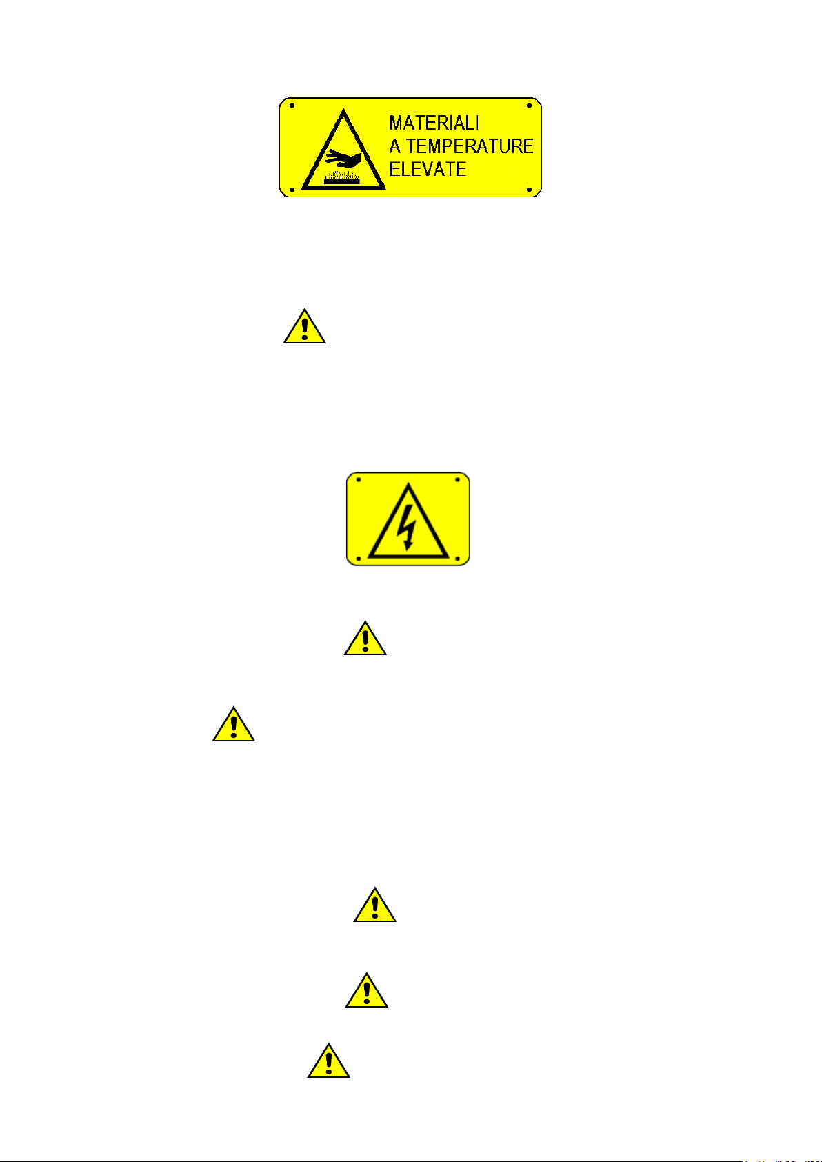
DANGER OF BURNS
The machine, by the very nature of the activity for which it is intended, presents the danger of burns.
Any burns can cause:
-From prolonged contact with the covers and the bodywork during the execution of a high-temperature
ironing session.
-From the contact with the components that convey the steam.
-From the contact with the components that convey the air and exhaust fumes.
-Din contact with the fabric leaving the machine.
-Contact with the heating roller during "hot" maintenance operations.
-Don contact with extracted tissues after being trapped between the cylinder and the bands.
The following plates have been affixed to the machine, in case of damage to them, the user must replace them
with identical ones.
E170301x.03_EN 29/06/2022
5
The machine must always and only be used by professionally trained personnel and in the presence of at least
one other operator!
READ CAREFULLY AND INFORM ALL OPERATORS ABOUT INTERVENTION SYSTEMS IN CASE OF
SUDDEN POWERFAILURE.
DANGER OF ELECTROCUTION
Any intervention on the electrical parts of the machine must be carried out only by qualified personnel and after
removing the power supply to the machine.
The power and control circuits can only be tampered with by the manufacturer's staff, under penalty of
forfeiture of the warranty conditions.
On the electrical panel there is the following monitor plate that must be replaced with an identical one in case it
has been damaged or removed.
It should be noted that, with reference to electrical hazards, the machine has been designed by the regulations
and described in the certificate of conformity delivered with the machine.
ATTENTION!
ATTENTION! Even when the position of the main switch is "0", the cables upstream of the switch are in
voltage!
PSYCHOPHYSICAL CONDITION OF THE OPERATOR
The operators involved in the machinery must be in perfect psychophysical condition; during the work, the
vertical posture must be assumed in front of the machine. Abrupt movements or uncontrolled gestures must be
avoided, for example during the picking and insertion of the fabrics to be ironed to avoid dangerous collisions
with the machine frame.
If other operators or other personnel are present, these must not be a source of distraction for the operator in
charge of the machine.
During the use of the machine, the operator must not be distracted by televisions, radios, etc. nor be subject to
any other source of distraction.
LIGHTING
In the room where the machine is installed, there must be uniform illumination of intensity 300-500 lux,
annoying glare must also be avoided.
ATTENTION!
In the case of gas Ironer, the flue gases must be evacuated according to the regulations in force on the subject.
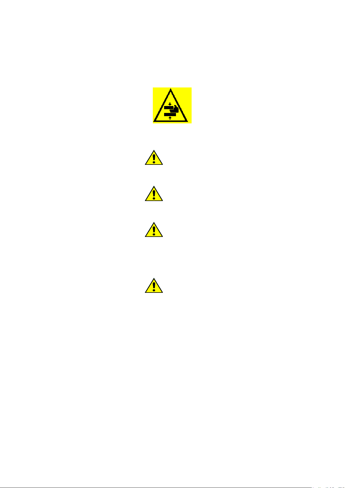
DANGER OF CRUSHING
E170301x.03_EN 29/06/2022
6
The operator, when introducing the fabric into the machine, must not go with it under the hand protection. The
fabric must be flattened on the entrance table, here ripples or bends must be eliminated; therefore, the fabric
must be gone with on the introduction bands that will drag it between the roller and the ironing bands.
It is forbidden to iron fabrics folded into several layers or several layers of overlapping fabric.
On the machine, in correspondence with the hand protection is affixed the following plate that must be replaced
with another identical one in case the same has been damaged or removed.
In order to avoid sunburn or crushing of the limbs, it is absolutely forbidden to remove, even temporarily, the
protection panels and security systems!
ATTENTION!
It is forbidden to introduce bars, slats or metal objects between the ironing bands and the roller. If an
emergency, always perform the procedures described in the relevant paragraphs.
ATTENTION!
Always check the correct functioning of the safety devices at each start of the machine, following the procedure
in the relevant paragraph.
ATTENTION!
It is mandatory to understand the logic of operation of the emergency buttons!
CAREFULLY READ AND INFORM ALL OPERATORS ABOUT THE INTERVENTION SYSTEMS IN
CASE OF SUDDEN POWER FAILURE OR IN CASE OF ENTRAPPING: CHECK THE POSITION OF THE
UNLOCKING SYSTEMS!
ATTENTION!
These warnings do not cover all possible risks. The user must therefore continue with the utmost caution in
compliance with the rules.
E170301x.03_EN 29/06/2022
7
3. RESPONSIBILITY OF THE MANUFACTURER
The instructions in this manual do not replace but supplement the obligations for compliance with current legislation on
safety and accident prevention standards. With reference to what is reported in this manual, the manufacturer declines
all responsibility if:
- use of the machine contrary to the laws in force on safety and accident prevention.
- incorrect installation of the machine.
- lack of periodic and scheduled maintenance
- failure or incorrect observance of the instructions provided in the manual.
- defects in voltage and mains supply.
- unauthorized modifications to the machine.
- use of the machine by unauthorized personnel.
- use of the machine different from the labeling of fabrics
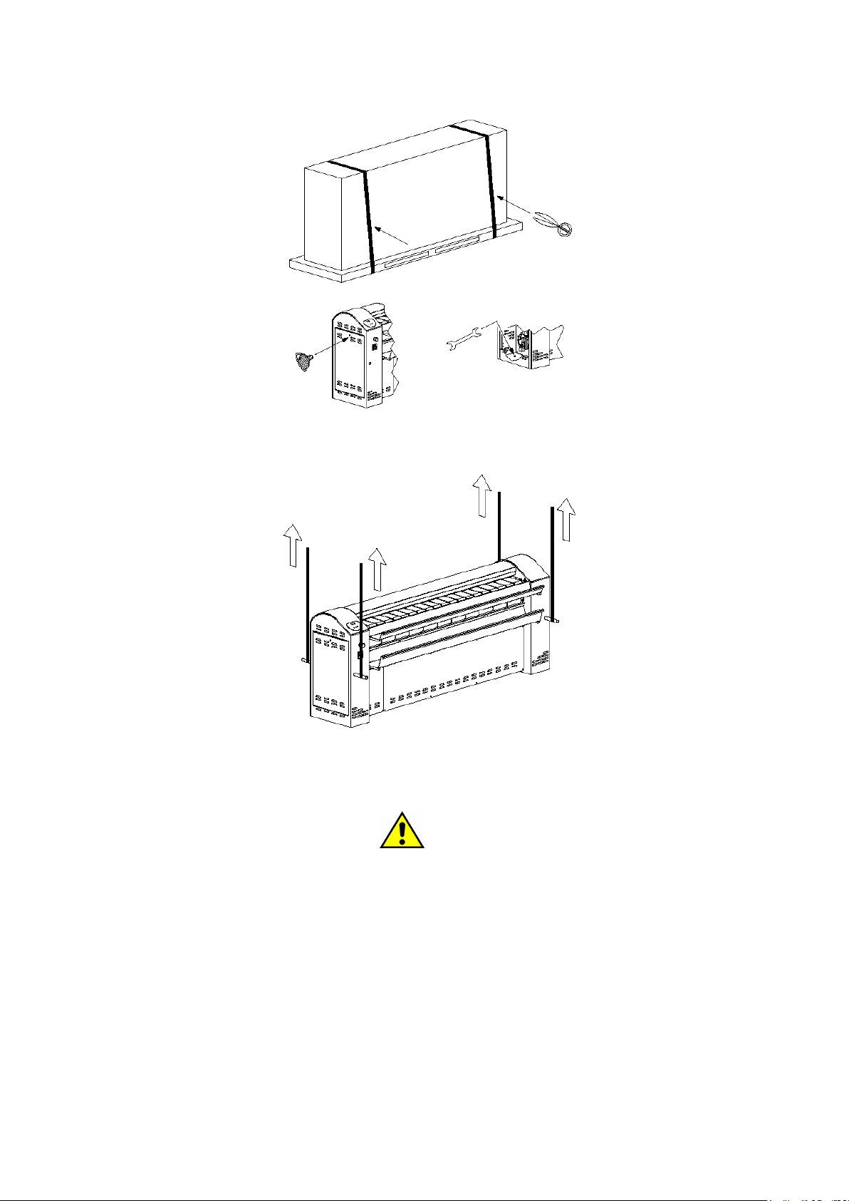
4. STORAGE AND UNPACKING
The machinery must be transported and stored in rooms where temperature and humidity do not exceed the following
values:
- TEMPERATURE: -25°C / +55°C.
- RELATIVE HUMIDITY: max 90% without condensation.
The storage of the machine in environments and methods different from those showed above can compromise the
electronic components contained within it.
It is recommended to check the machine upon receipt, taking care to report to the carrier any damage caused during
transport, both to the internal components and to the external bodywork.
The machine must be completely unpacked near the place of installation.
The packaging materials must not be dispersed in the environment and must be stored in the proper collection spaces
according to current regulations.
Remove the fixing bolts to the pallet with a wrench.
The machine must be moved, in transport from the carrier to the place of installation, by a forklift by inserting the
forklifts only and exclusively in the prepared locations.
ATTENTION!
During the handling phase, use a forklift truck that is compatible with the weights to be lifted: carefully check
the data reported in the technical sheets. Perform each movement of both moving and lifting/lowering very
slowly.
ATTENTION!
Handling by the forklift truck must be carried out only by qualified and competent personnel.
Once the installation site is reached, the machine must be completely unpacked, freeing it from packaging. Open both
side doors with the proper key and remove the fixing bolts to the pallet, visible at the base of the shoulder of the
machine.
E170301x.03_EN 29/06/2022
8
To get the grille off the pallet, use two steel bars with the smallest diameter of 20 mm and a length of at least 800 mm,
passing them through the prepared holes. Then harness the machine and lift it perfectly vertically.
Lift the machine with the forklift and remove the pallet: finally place the machine in the final position.
The packaging materials must not be dispersed in the environment and must be stored in the proper collection spaces,
according to local regulations in force.
ATTENTION!
Proceed to the disassembly of any transport stops following the instructions inside the shoulders of the machine.
Care should be taken to store pallets and transport stops for any future movement of the machine to other
locations.
NOTE: The machine must not be left on the pallet!
Once the machine positioning operations have been completed, the following parts have been mounted on the proper
supports, delivered in the same packaging, but disassembled:
- top collection chute
- lower collection chute
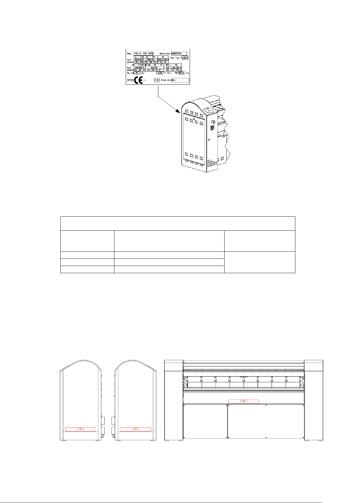
5. MACHINE IDENTIFICATION
The equipment is identifiable by an adhesive plate bearing the serial number, model, power, and technical
characteristics. Spare parts and / or interventions presuppose the exact identification of the model for which they are
intended.
E170301x.03_EN 29/06/2022
9
Tampering, removal, lack of identification plates or anything else that does not allow the safe identification of the
machine, makes any installation and maintenance operation difficult and automatically voids the warranty.
The washing machines described here are intended exclusively for washing fabrics in water and are intended for the
commercial, professional, industrial sectors.
MODELS AND MAXIMUM LOAD CAPACITY
MODELS AND MAX LOAD CAPACITY
MODEL / TYPE
IRONING TABLE WIDTH
IRONING TABLE WIDTH
(mm)
ROLLER DIAMETER
ROLLER DIAMETER
(mm)
MCA 150
1500
300
MCA 180
1800
MCA 210
2100
The models described above are intended for drying and ironing flat linen in the industrial field.
6. INSTALLATION AND POSITIONING
All installation operations must be carried out by professionally qualified personnel. Place the machine on a flat surface
in a stable and horizontal way, using the adjustable feet placed at the base of the sides. Check the correct bubble
positioning of the machine. Check the correct leveling of the machine as follows:
- Check the leveling first on one side, and then on the other side of the machine
- Then check the leveling in the central part of the machine
-
E170301x.03_EN 29/06/2022
10
ATTENTION!
If the machine cannot be installed respecting the criteria below, it is necessary to request the right
transformations from the manufacturer.
Please note that for proper use, operation, and maintenance, it is necessary to leave a free space of at least 500 mm from
the rear panel of the machine.
ATTENTION!
To perform ordinary and extraordinary maintenance, leave on both sides of the machine, a free space at least
equal to the length of the machine itself!
The ambient temperature must be between +5°C and +40°C.
The smooth operation of the machinery is guaranteed in environments where the residual humidity is not higher than
50% at a temperature of +40 ° C.
The machinery may not be installed at altitudes above 1000 m above sea level.
The degree of protection is IP 22.
The support surface must have a minimum capacity of 500 kg/m2: the load of the machinery can be considered static.
The machine must be placed in a well-ventilated room (by the laws in force).
In the room, an air exchange proportional to that subtracted from the operation of the machinery must be ensured.
The ventilation air must be taken directly from the outside, in an area far from sources of pollution, and the influx must
be guaranteed by permanent openings made on the walls of the room that give outwards. The calculation of the net total
free section must be conducted by the regulations in force on the subject.
ATTENTION!
The machine MUST NOT be installed outdoors, but in a CLOSED environment specifically built and used as a
laundry.
7. INDICATIONS ON SOUND EMISSION
The airborne noise produced by the machine produces an "A" weighted continuous sound pressure level of less than 70
dB.
8. FLUE GAS EXHAUST PIPE (ONLY FOR GAS MACHINES) AND WET AIR DUCT
The flue gas exhaust pipe (for machines with gas heating) must be made according to current regulations. In the case of
gas operation, the chimney must be spaced (at least 500 mm) from combustible or highly flammable materials by an air
gap or insulating materials. If this distance cannot be maintained, it is necessary to provide appropriate specific
protection for heat.
The flue gas exhaust pipe can have a maximum length of 15 meters (diameter 100 mm) and must be insulated or made
so that any condensate can be collected. For lengths longer than 15 meters, the Installer must contact the manufacturer.
The exhaust pipe, the connection to the chimney and the chimney must be made in compliance with local and national
rules and / or regulations in force. The use of rigid ducts is mandatory; the joints between the elements must be airtight
and all components must be resistant to temperature, condensation, and mechanical stress. Flues that are not adequately
sized or poorly shaped, amplify the noises of combustion and give rise to condensation problems. They can also
interfere with combustion parameters, favoring the formation of soot and scale. To avoid leakage of flue gas and noise,
the joints must be made hermetic, with materials (stucco, mastics, silicone preparations) resistant to high temperatures.
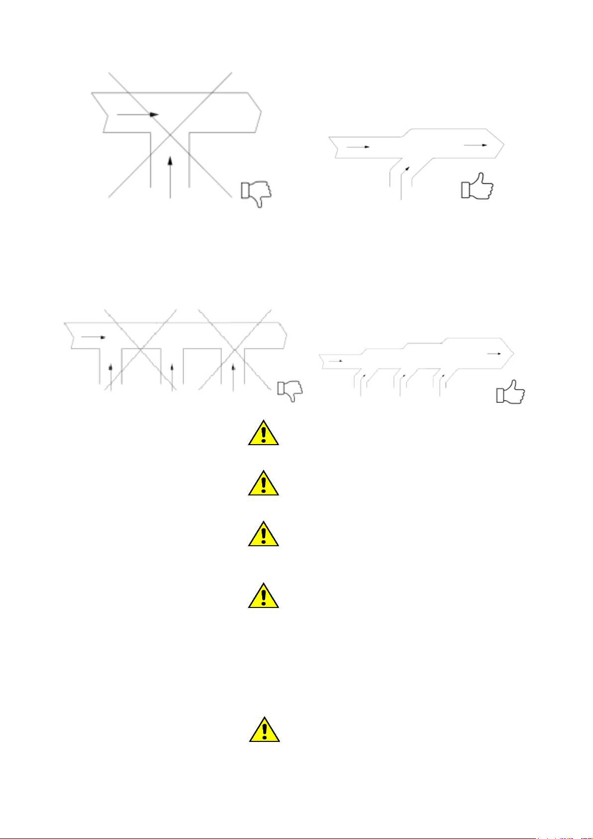
In case of connection to existing exhaust manifolds, the connection should never be made to "T", but always to "Y" (see
figures below).
E170301x.03_EN 29/06/2022
11
The assembly of a manifold to unify the exhaust pipe of several machines cannot be carried out for smoke outlets: the
smoke outlets must remain independent and flow outside the installation room.
For machines with electric heating, it is possible to supply a collector to unify the humid air outlets: do not make "T"
connections and consider the correct value of the collector section. If necessary, support an increase in the collector
section.
ATTENTION!
Wet air ducts and smoke evacuation ducts must never be joined.
ATTENTION!
The outlet of the exhaust pipe must not flow at human height and/or be directed towards residential units.
ATTENTION!
Instruct the user on the danger of tampering with the exhaust pipes and/or changing, plugging, obstructing, or
reducing the ventilation openings of the installation space.
ATTENTION!
Do not insert your hands objects inside the drain (size. 6). On this connection must be exclusively connected the
smoke evacuation chimney and humid air.
With regard to the dimensions and dimensions of the smoke and humid air exhausts, please refer to the attached
technical sheet.
9. ELECTRICAL CONNECTION
ATTENTION!
The electrical connection must be carried out by professionally qualified personnel and must meet the
requirements of current local and national rules and / or regulations.
E170301x.03_EN 29/06/2022
12
Check that the supply voltage corresponds to that showed in the license plate data (voltage tolerance ±10%,
frequency tolerance ±1Hz).
License plate data is visible on the back of the car.
For the connection use a cable of type H05 VV –F or higher sized as reported in the license plate data. The following
minimum sections are suggested:
1500
1800
2100
electric heating
5x10mm2
5x10mm2
5x10mm2
steam/gas heating
5x2.5mm2
5x2.5mm2
5x2.5mm2
ATTENTION!
The minimum sections listed above may vary depending on the length of the connection. For lengths longer than
5 meters, increase the section proportionally to the added length.
ATTENTION!
The connection of the machine must always be carried out according to the matricular data (power, supply
voltage, frequency). For supply voltages other than those envisaged, request information from the manufacturer.
ATTENTION!
If the power supply comes from a diesel generator, the inverter requires the application of an added inductance.
Interpose upstream of the appliance an omni polar disconnection device (e.g., a differential circuit breaker) with an
opening between the contacts that allows complete disconnection under the conditions of surge category III and follows
the relevant regulations in force. The breaking power of the circuit breaker shall be at least 10 kA.
ATTENTION!
Before switching on equipment that has undergone a thermal shock, wait for evaporation any moisture is
condensed to avoid possible damage to the electronic components.
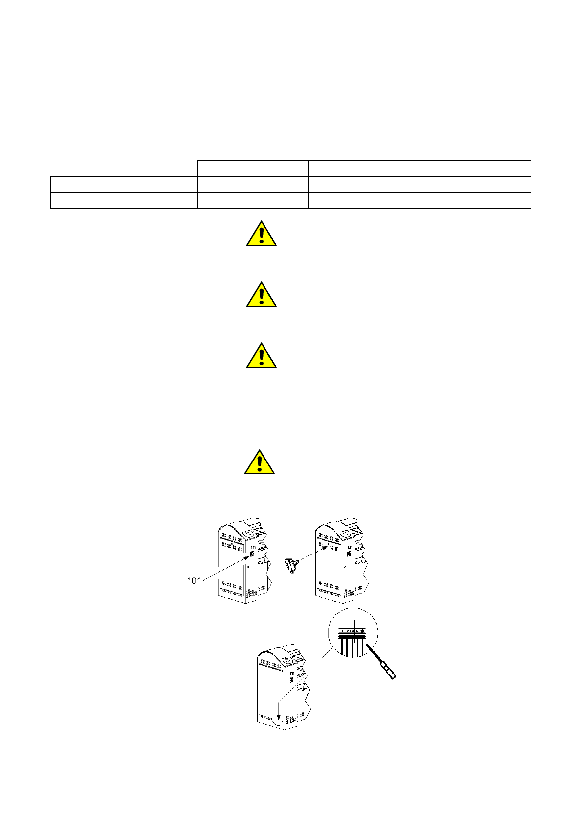
Make sure the main switch is in the "0" position.
Open the side door using the key that is delivered with the machine documentation.
E170301x.03_EN 29/06/2022
13
Remove the door.
Pass the power cord through the hollow press on the left shoulder of the grille.
The power supply must be carried out by connecting the cable to a series of terminals (already present in the appliance):
Depending on the type of power supply provided by the serial number plate of the machine, connect the wires to the
disconnector contacts marked as follows:
: terminal for the equipotential connection with the grounding system of the user.
L1, L2, L3: phase terminals
N: neutral terminal
When installing or replacing the power cord, the ground conductor must be at least 5 cm longer than the others.
ATTENTION!
In the event that the intake fans are powered by a three-phase system, check that the direction of rotation of the
motors is correct and in the direction of air expulsion.
In the event that the fan motors turn in the wrong direction, reverse the position of two power phases.
ATTENTION!
In the event that the machine is with gas heating, check the correct phase and neutral position in single-phase
machines. Incorrect connection can result in the ionization sensor not being detected.
ATTENTION!
The appliance must be connected to an effective ground system: the manufacturer declines all responsibility in
the event that this connection is not carried out according to the provisions of the regulations in force on the
subject.
Before any maintenance disconnect the power supply: for maintenance refer to the wiring diagram of the machine,
inserted inside the machine or available on the manufacturer's website.
ATTENTION!
Even when the position of the main switch is "0", the cables upstream of the switch are in voltage!
10. LEAK TEST (only for gas Ironer)
All fittings between the system and the appliance are to be subjected to a leak test. For this operation it is recommended
to use a spray for leaks; otherwise, you can brush the siding points with other foamy substances, which do not cause
corrosion. Whichever solution is adopted, bubbles should not develop. In the event that there are leaks, proceed to their
elimination.
ATTENTION!
It is absolutely forbidden to use open flames for the leak test!
11. GAS CONNECTION: THERMAL POWER (only for gas Ironer)
All equipment during the final testing at the factory is prepared for the type of gas reported on the adhesive plate found
near the serial number plate.
E170301x.03_EN 29/06/2022
14
If the preparation of the appliance does not correspond to the family of gas available on site, it is mandatory to carry out
a transformation of the appliance for adaptation to the type of gas present. In this case it is absolutely necessary to
inform the authorized technical service center.
The commissioning of the appliance with the expected thermal power depends on the inlet pressure and calorific value
of the gas as well as the nozzle, the pressure to the same and the correct supply of primary air.
The inlet pressure that allows the operation of the appliance is included for the several types of gas within the limits
indicated in the following table. Outside these limits, the commissioning of the apparatus is prohibited. If a pressure
different from what is shown in the table is found, it is advisable to consult the body or company that supplies the gas or
the company that carried out the plant.
The lower calorific value of the gas is needed from the entity or company that supplies the gas and must correspond to
what is reported in the technical sheet
12. GAS CONNECTION: INLET PRESSURE CONTROL (only for gas cylinders)
The gas connection must be conducted by professionally qualified personnel and must meet the requirements of current
local and national rules and/or regulations. Check that the supply gas follows that indicated in the technical data plate
located in the rear of the machine.
The largest inlet pressure is 50 mBar.
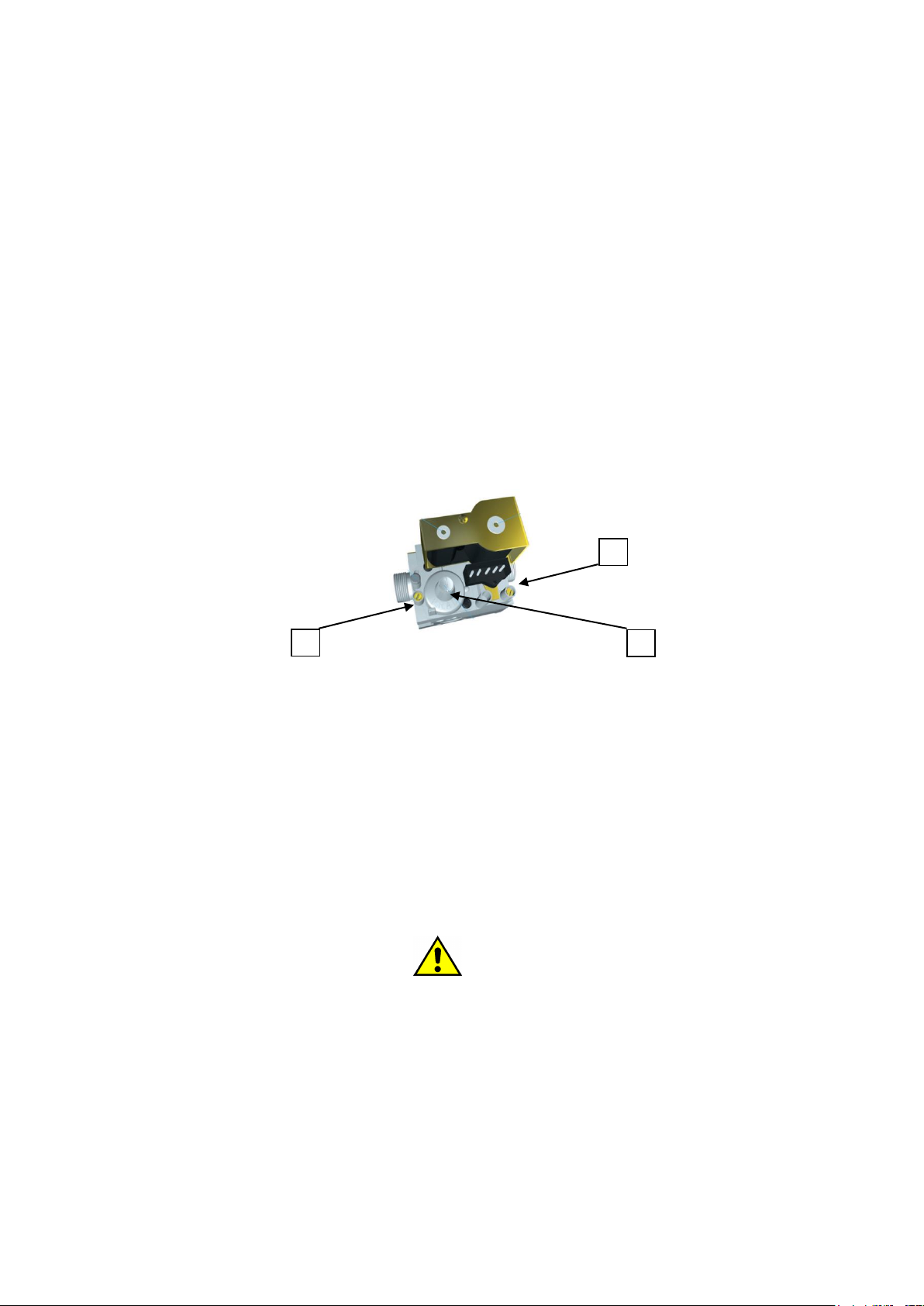
Below is the sign for any pressure checks by means of a pressure gauge.
1) inlet pressure socket
2) outlet pressure taking shows the pressure at the burner
3) pressure regulator
The loose safety screws for pressure measurement, MUST ABSOLUTELY be screwed back once the measurement has
been carried out.
Check the correct positioning of the adjustment collar (if any). Con machine in operation, and side doors closed, check
the correct pressure at the nozzle: use the following table.
For feeding from the network use an approved pipe: the pipe must be equipped with an expansion ring in case the pipe
is rigid.
For the dimensions of the gas supply pipe refer to the attached technical sheet: the external pipes must be adapted to the
type of gas used and follow the current legislation of the country of destination. Install a suitably sized pressure reducer
on the gas supply line and equip the line with a manually closing valve.
ATTENTION!
Gas valves have a pressure limit of 50mbar. Exceeding this pressure can cause the valve membranes to rupture.
Therefore, perform a correct check of the pressure available upstream of the machine, before connecting the gas
supply.
1
2
3
E170301x.03_EN 29/06/2022
15
1500
DEVELOPING COUNTRIES
Nozzle
pressure[mbar]
Nozzle diameter1/100
Primary
diaphragm
Power.kW
G20
AL, BA, BG, HR, MK, UADK, FI, SE, BG, EE, LV, LT,
CZ, SI, TR, HR, RONOLU, PLNLES, GB, GR, IE, IT, PT,
SKFR, BEDEAT, CHHU
7,5
440
C=20
22,41
G20
FR, BE
18,8
350
C=20
22,89
G25
DE
11
440
D=15
22,24
G25.3
NL
11
440
D=15
22,52
G30/31
CY, MT, NL, NO, HUAL, BA, BG, HR, MK, UADK, FI,
SE, BG, EE, LV, LT, CZ, SI, TR, HR, ROPLAT, CHDE
27,7
235
B=25
22,32
G30/31
LU, FR, BEES, GB, GR, IE, IT, PT, SK
excluding regulator
235
B=25
22.32

E170301x.03_EN 29/06/2022
16
1800
DEVELOPING COUNTRIES
Nozzle
pressure[mbar]
Nozzle diameter1/100
Primary
diaphragm
PowerkW
G20
AL, BA, BG, HR, MK, UADK, FI, SE, BG, EE, LV, LT,
CZ, SI, TR, HR, RONOLU, PLNLES, GB, GR, IE, IT, PT,
SKFR, BEDEAT, CHHU
8,5
440
A=30
24.79
G20
FR, BE
18,9
365
B=25
25,75
G25
DE
12,5
440
B=25
24,3
G25.3
NL
12,6
440
- - -
24,46
G30/31
CY, MT, NL, NO, HUAL, BA, BG, HR, MK, UADK, FI,
SE, BG, EE, LV, LT, CZ, SI, TR, HR, ROPLAT, CHDE
28,1
245
open
25,81
G30/31
LU, FR, BEES, GB, GR, IE, IT, PT, SK
excluding regulator
245
open
25,81
E170301x.03_EN 29/06/2022
17
2100
DEVELOPING COUNTRIES
Nozzle
pressure[mbar]
Nozzle diameter1/100
Primary
diaphragm
PowerkW
G20
AL, BA, BG, HR, MK, UADK, FI, SE, BG, EE, LV, LT,
CZ, SI, TR, HR, RONOLU, PLNLES, GB, GR, IE, IT, PT,
SKFR, BEDEAT, CHHU
8
480
B=25
26,8
G20
FR, BE
18,6
380
B=25
26,89
G25
DE
11
480
C=20
25,86
G25.3
NL
11,1
480
C=20
26.16
G30/31
CY, MT, NL, NO, HUAL, BA, BG, HR, MK, UADK, FI,
SE, BG, EE, LV, LT, CZ, SI, TR, HR, ROPLAT, CHDE
27,9
255
B=25
25,65
G30/31
LU, FR, BEES, GB, GR, IE, IT, PT, SK
excluding regulator
255
B=25
25,65
E170301x.03_EN 29/06/2022
18
13. GAS CONNECTION: TESTING
As soon as the connection work is completed, the appliance and the entire installation must be checked. In particular,
check:
-that the connections are made by the requirements and indications of this manual.
-that all the safety requirements of the standards, laws and directives in force are met.
-that the gas connections made are watertight.
The equipment is then switched on according to the instructions in the user manual, checking the progressive ignition of
the burners and the appearance of the flame.
Carry out a control of gas consumption by the volumetric method. Detecting through the meter how much gas has been
consumed in a given unit of time: the resulting value is to be compared with the values shown in the table.
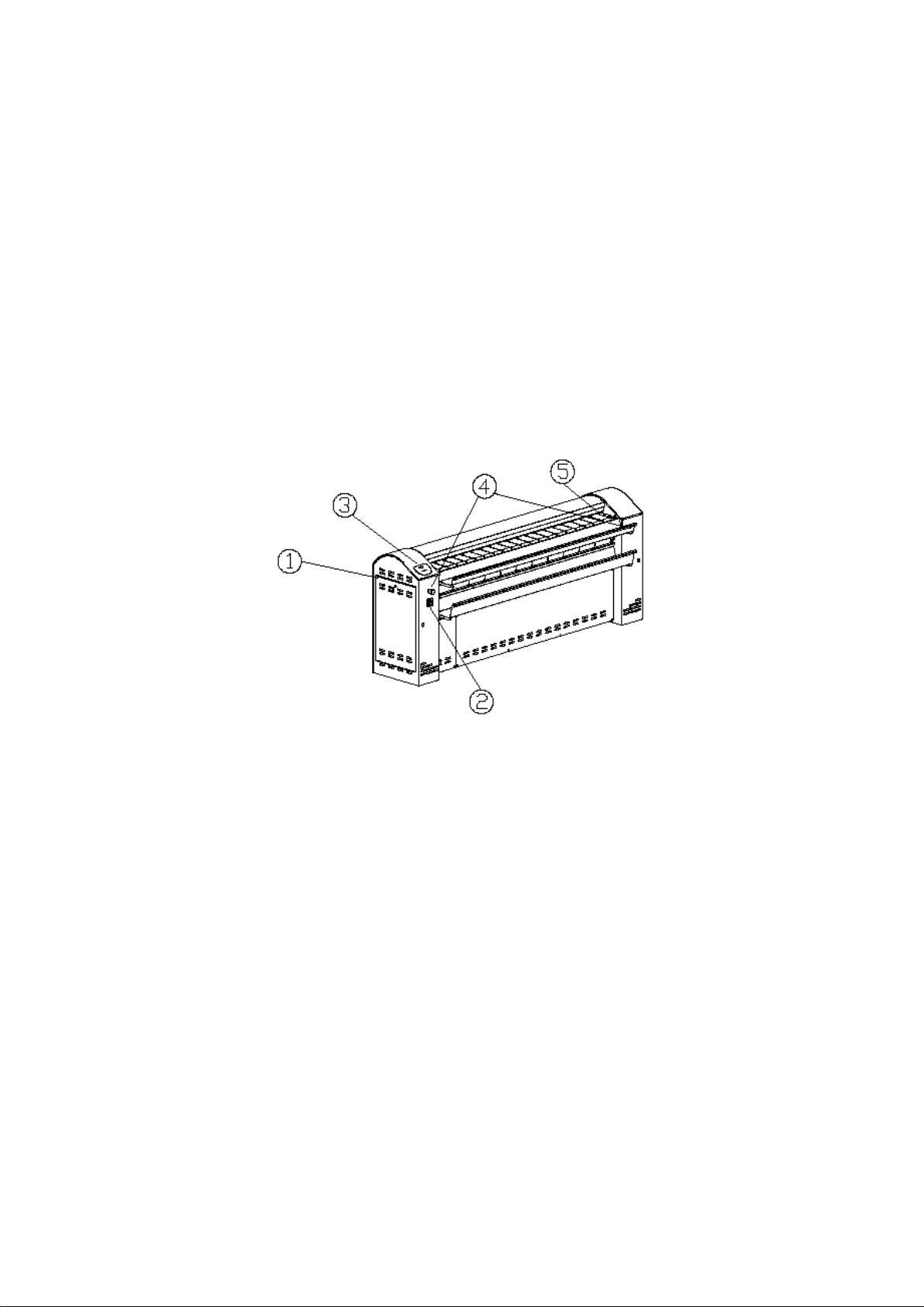
14. GETTING TO KNOW THE DRYING GRILLE
The drying grille is characterized by some elements that it is better to know at once, before starting to use the machine.
With point 1 the access door to the electrical panel of the grille is found. The flap can be opened using the plastic key
that is delivered with the machine documentation. Access to the electrical panel must be allowed only to specialized and
competent personnel.
With point 2 the main switch is found: when you operate it bringing it to the "I" position, you power the machine
electrically.
Point 3 finds the control microprocessor of the grille.
Point 4 shows the emergency mushrooms that must be pressed whenever it is necessary to stop the Ironer roller quickly.
Step 5 finds the hand save bar: when pressed, the machine stops.
15. WORK CYCLE
During operation it must be remembered to use the entire length of the roller, so as to keep uniform temperature over
the entire length of the machine.
The temperature to be used must follow the temperatures allowed by the characteristic plates of the fabrics to be ironed.
Also remember that the conditions of residual moisture of the fabrics to be dried and ironed should not be more than
50%. The drying Ironer must therefore be used on fabrics that have been centrifuged with a high centrifugation G-factor
washing machine ≥ 300. Its purpose is to dry and simultaneously iron the flat garments.
The productivity values detectable by the technical data sheets are recorded according to ISO 9398.
E170301x.03_EN 29/06/2022
19
ATTENTION!
The formation of yellow stains on the stretched fabrics, signals the presence of detergent not carefully eliminated
during rinsing!
The formation of folds on the stretched fabrics can be generated by too low residual moisture. Also pay attention
to the thicknesses of the fabrics. Significant differences in thickness (due, for example, to the lateral seams), can
give rise to the formation of wrinkles and difficulties of insertion.
Even the passage of a double or folded fabric can be the origin of folds or curls, therefore it should be avoided.
The ironing work must not begin until the minimum temperature of 80 ° C is reached, and in any case not before
the minimum temperature necessary for the ironing of the fabrics during processing is reached.
In case of emergency and need for a quick stop of the machine, press one of the emergency buttons on the sides
of the machine. When the emergency button is pressed, the ironing roller stops sand the temperature is above 80
° C, you can burn the ironing bands. If the machine cannot be restarted, use damp sheets by passing them
between roller and bands, and rotating the roller by hand as described in the relevant paragraph. The operation
must be repeated until the temperature drops below 80 ° C.
The ironing area is delimited by ironing bands and introduction bands. Ironing on the outside of the
introduction bands can give rise to stains on the fabrics.
Ironing must be carried out scrupulously following the indications given in the labeling of the fabrics.
In case of absence of labeling, check the composition of the fabrics before deciding on the ironing temperature.
Pay special attention to mixed fabrics and fabrics with seams of heterogeneous material.
16. WHAT TO DO IN CASE OF ENTRAPPING
The risk is reduced by the presence of hand-saving protection. In the event that, however, the entrapping of a limb
occurs, it is necessary to be able to manually reverse the rotation of the roller, so as to be able to free the limb.
In this case, follow these steps.
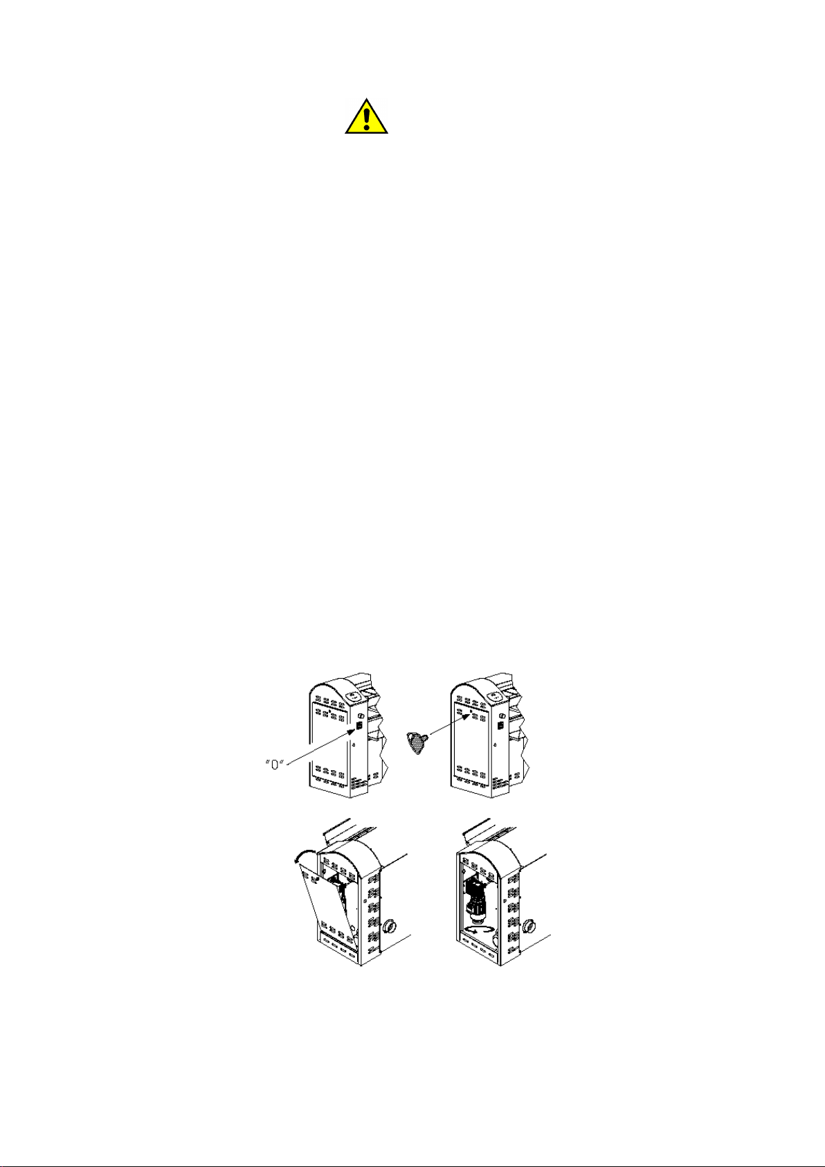
Remove the power supply by turning the main switch by placing it on "0".
Use the key, supplied with the documentation, to open the lock of the side door.
Open the door by rotating it on the base
Rotate the flyer:
- clockwise: to turn the roller in the opposite direction to the ironing and free the possibly trapped limb.
E170301x.03_EN 29/06/2022
20
ATTENTION!
If the temperature of the roller is high (above 80°C), continue to insert wet fabrics over the entire length of the
roller, and continue to rotate the roller by hand, to avoid burning of the ironing bands.
Once completed, close the door with the key and wait for the return of the power supply.
When the power supply returns, turn the main switch by placing it on "I". The microprocessor display turns on again
and the machine is placed on standby, waiting for a new start-up command.
ATTENTION!
To make sure that all the personnel who use the machine have well understood the procedure to possibly free a
trapped limb. Perform six-monthly exercises to verify the correct understanding of the procedure.
17. WHAT TO DO IN CASE OF LACK OF ELECTRICITY
If the power supply is lost, it is possible that one or more garments stay inserted between the roller and the ironing
bands risking burning out.
It is also possible that, if the temperature is above 80 ° C, even the ironing bands risk burning.
In this case, follow these steps. Remove the power supply by turning the main switch by placing it on "0".
Use the key, supplied with the documentation, to open the lock of the side door.
Open the door by rotating it on the base
Rotate the flyer:
- counterclockwise: to turn the roller in the direction of ironing and extract the linen stuck
At the same time, insert fabrics with the usual ironing methods, along the entire length of the roller, to lower the
temperature.
ATTENTION!
If the temperature of the roller is high (above 80°C), continue to insert wet fabrics over the entire length of the
roller, and continue to rotate the roller by hand, to avoid burning of the ironing bands.
18. WORK CYCLE: VERIFICATION OF SAFETY SYSTEMS
After turning on the machine, before starting work, it is necessary to check the perfect functioning of the safety devices.
The operator must perform the following procedure each time the machine is started.
ACTION to be performed
REACTION to be obtained
Press the ON/OFF button on the digital keyboard
→
The cylinder MUST begin rotation.
Press the ON/OFF button on the digital keyboard
The cylinder MUST stop the rotation
Start the rotation of the roller: push the hand
protection.
Repeat the operation of pushing the hand protection
in at least three places: in the center and 50 cm from
the right end and from the left end.
→
In all three tests, the roller MUST stop: the SAFETY
RESET button MUST be switched on.
Start the rotation of the roller: take turns running the
right emergency buttons.
→
The roller MUST stop: the SAFETY RESET button
MUST turn on.
Once the preliminary operations of verification of the efficiency of the safety systems have been completed, it is
possible to start the ironing cycle.
Table of contents
Other Imesa Industrial Equipment manuals


Popular Industrial Equipment manuals by other brands

Delachaux
Delachaux Conductix-Wampfler 0314 Series installation manual

Schaeffler
Schaeffler YRTC Fitting manual

ABB
ABB HT590576 Operation manual

Danfoss
Danfoss MPE 70 operating guide

Schäfter+Kirchhoff
Schäfter+Kirchhoff 60FC-A19.5 Series quick start guide

SCHUNK
SCHUNK PFH 150 Assembly and operating manual


