Imesa TANDEM Quick start guide

E170701X.01_ENG 16/04/18
1
TANDEM
INSTALLATION,
USE AND MAINTENANCE
INSTRUCTIONS
PRESERVE FOR FUTURE
CONSULTATION
IMESA S.p.A.
via degli Olmi 22
31040 Cessalto (TV)
ITALY

E170701X.01_ENG 16/04/18
2
INDEX
INDEX............................................................................................................................................................... 2
1. INTRODUCTION........................................................................................................................................ 4
2. SAFETY RULES........................................................................................................................................ 5
3. MANUFACTURER LIABILITY................................................................................................................. 6
4. UNPACKING .............................................................................................................................................. 6
5. MACHINE IDENTIFICATION................................................................................................................... 7
6. INSTALLATION AND POSITIONING .................................................................................................... 8
7. INSTALLATION: GAS HEATED MACHINES SPECIFICATIONS.................................................... 9
8. NOISE LEVEL............................................................................................................................................ 9
9. ELECTRIC CONNECTION..................................................................................................................... 10
10. EMERGENCY STOP IN SELF SERVICE CONFIGURATION....................................................... 11
11. GAS CONNECTION.............................................................................................................................. 11
12. GAS CONNECTION: TIGHTNESS TEST ......................................................................................... 11
13. GAS CONNECTION: THERMAL POWER........................................................................................ 12
14. GAS CONNECTION: GAS INLET PRESSURE CONTROL.......................................................... 12
15. GAS CONNECTION: FINAL TEST .................................................................................................... 12
16. HUMID AIR AND BURN GAS EXAUST............................................................................................ 12
17. STEAM CONNECTION ........................................................................................................................ 13
18. COMPRESSED AIR CONNECTION.................................................................................................. 14
19. HYDRAULIC CONNECTION: LOAD ................................................................................................. 14
20. HYDRAULIC CONNECTION: DRAIN................................................................................................ 15
21. MACHINE DESCRIPTION .................................................................................................................. 15
22. MASCHINE START AND FINAL TEST............................................................................................. 15
23. LANGUAGE CHANGE......................................................................................................................... 15
24. REMOTE ASSISTANCE SERVICE ACTIVATION .......................................................................... 16
25. HOW TO PREPARE THE LINEN: WASHING MACHINE.............................................................. 17
26. HOW TO LOAD THE MACHINE AND CLOSE THE DOOR.......................................................... 17
27. DOOR MANUAL OPENING................................................................................................................. 17
28. HOW TO SWITCH ON THE MACHINE............................................................................................. 20
29. HOW TO SELECT A PROGRAM....................................................................................................... 20
30. PREFERED PROGRAMS.................................................................................................................... 21
31. DELAYED START................................................................................................................................. 21
32. RUNNING THE PROGRAM................................................................................................................. 22

E170701X.01_ENG 16/04/18
3
33. PROGRAM PAUSE............................................................................................................................... 22
34. RAPID ADVANCE................................................................................................................................. 22
35. PROGRAM END.................................................................................................................................... 23
36. END OF THE WORKING DAY: WASHING MACHINE .................................................................. 23
37. PROGRAMMING................................................................................................................................... 23
38. PROGRAM MODIFICATION............................................................................................................... 23
39. EASY PROG FUNCTION..................................................................................................................... 26
40. SELF DIAGNOSTICS ........................................................................................................................... 29
40. FACTORY PROGRAMS: WASHING MACHINE............................................................................. 33
42. OTHER FUNCTION............................................................................................................................... 34
43. WASHING MACHINE MAINTENANCE............................................................................................. 34
44. WASHING DEFECTS ........................................................................................................................... 35
45. SAFETY DEVICES CONTROL........................................................................................................... 35
46. PREPARE THE LINEN FOR DRYING............................................................................................... 35
47. START A PROGRAM: DRYER........................................................................................................... 36
48. PROGRAM START DELAYED........................................................................................................... 38
49. PROGRAM PAUSE............................................................................................................................... 38
50. PROGRAM STOP.................................................................................................................................. 38
51. PROGRAM STEPS OF DRYING........................................................................................................ 39
52. END OF A WORKING DAY: DRYER................................................................................................. 39
53. PARAMETERS MODIFICATIONS DURING THE CYCLE............................................................. 39
54. MANUAL CONFIGURATION .............................................................................................................. 39
55. SAVED PROGRAMS............................................................................................................................ 40
56. COIN OP DRYER: HOW IT WORKS................................................................................................. 41
57. HOW TO ACCES TO THE PROGRAM AREA................................................................................. 42
58. PROGRAMS........................................................................................................................................... 42
59. PROGRAM: LANGUAGE SELECTION ............................................................................................ 43
60. PROGRAM: DATE/TIME...................................................................................................................... 43
61. PROGRAM: ENERGY CONSUMPTION........................................................................................... 43
62. PROGRAM: NO WRINKLE ................................................................................................................. 43
63. PROGRAM: INITIAL COOLING ......................................................................................................... 44
64. PROGRAM: PAYMENT SYSTEM...................................................................................................... 44
65. PROGRAM: COIN BOX MENU........................................................................................................... 44
66. EMERGENCY STOP BUTTON........................................................................................................... 44
67. BLACK OUT........................................................................................................................................... 44
68. WHAT MUST BE DONE IN CASE OF GAS SMELL ...................................................................... 44

E170701X.01_ENG 16/04/18
4
69. DISPLAYED WARNING....................................................................................................................... 45
70. DRYER MAINTENANCE...................................................................................................................... 46
71. DRYING PROBLEMS........................................................................................................................... 47
72. SAFETY DEVICE CONTROL.............................................................................................................. 48
73. SCRAPPING........................................................................................................................................... 48
74. WARRANTY CONDITION.................................................................................................................... 49
75. GAS PRESSURE................................................................................................................................... 49
TRANSLATION OF ORIGINAL INSTRUCTIONS
In the event of any disputes, the reference text will be the Italian version.
1. INTRODUCTION
This manual refers to industrial tumble dryers and
washing machines. installation, use and
maintenance.
It is written in compliance with the European
Community rules in force. The information here
written are addressed to the installer and the user,
who must be sure to fully understand them before
use of the machine.
This manual must always be available for
consultancy. In case it should be lost or damaged,
ask for a new copy from the manufacturer.
The producer is not responsible for any
consequences coming from incorrect dryer use
due to incomplete or misreading of this manual.
The manufacturer reserves itself the right to
modify the specifications written in this manual or
the characteristics of each machine. Some
pictures in this manual may differ from reality.
Diagrams and technical data may be changed
without previous notice.
This manual is integrated by the following
attachments : UE declaration of conformity
technical data sheet and wiring diagram. All these
documents are contained in a envelope you’ll find
inside the machine.
The manual and its attachments are part of the
machine itself, so they must be kept together
and follow the machine when it is sold to
another user.
The manual Attachments and exploded views with
spare parts list can be retrieved in the technical
area of the manufacturer’s website.
Dryer serial number must be available when
entering in the web site.
ATTENTION!
Manufacturer is not responsible for any possible
incorrect information here written, when the errors
are due to a printing or translation error.
The manufacturer reserves themselves the right
to modify the product, when necessary or useful,
without changing the main characteristics. Without
any previous authorization of the manufacturer, to
copy completely or partially the next and the
pictures of this manual is forbidden.

E170701X.01_ENG 16/04/18
5
2. SAFETY RULES
ATTENTION!
Chocking, injury and permanent invalidate
risks!
Not respecting the following instruction, may
cause damages to people, things and animals.
Installations and maintenance of the here
described machines must be trained by
authorized personnel, which knows the product
and respecting the European Rules in matter of
industrial machines installation.
Reparation made in a not correct way may
seriously compromise the user safety.
Instruction must be read in detail before the
machine is put in use. Instruction must be
available to all the people working with the dryer.
Here described machines must be used for
professionally drying clothing and linen: any other
use is forbidden if not before authorized by the
manufacturer.
Before removing linen from the dryer, be sure that
the drum has stopped. Never put your hands
inside the drum, if it is still rotating.
Do not dry in the machine any dissimilar items; do
not dry linen, which has entered in contact with
dangerous materials like explosives, detonating
explosives or inflammables.
Follow always very carefully the cleaning
instruction of each linen.
To avoid risks off fire or explosion, do not
approach the machine with combustible or
inflammable substances.
The use of this machine is forbidden to people
under 16 years of age.
Children must not play or be close to this
equipment.
Packing materials must be kept out of the reach of
children.
Detergents must be kept out of the reach of
children. Children and pets must be kept away
from the equipment door when it is open.
External supplementary connection to the
machine releases the manufacturer from any
responsibility if they are not properly done.
WARNINGS
Working with opened sides is forbidden!
In order to avoid burns or accidents it is
forbidden to remove, even temporarily, the
protection panels and the safety system!
It is forbidden to introduce bars, sticks or
metallic objects inside the drum. In case of
emergency, please follow always the here
described procedures.
Each time the dryer is started, check always
the safety device is correctly working!
To know the machine and its safety device
working is compulsory!
BURNS DANGERS
The dryer, because of its nature, presents
burns danger.
Burns may be caused by:
-The contact with the linen taken out from
the dryer;
-The contact with the door inside, following
its opening;
-The contact with the heating batteries
during the maintenance;
-The contact with the fluxing steam parts.
Following labels are fixed on the machine. If
one of them would be damaged, the user must
replace it with a new identical one.
Stuck near dried linen exit.
External panels can reach high temperatures
E170701X.01_ENG 16/04/18
6
when the machine is working.
Dryer must always be used by trained
personnel and with at least two operators in
the room!
READ CAREFULLY THE INSTRUCTION FOR
OPERATING IN CASE OF BLACK OUT, AND
INFORM ALL THE USERs ABOUT THEM.
ELECTROCUTION DANGER
Only qualified personnel must operate any
service of the electrical parts. Before working
on the machine, cut off the electrical supply.
Only manufacturer personnel can modify
power and controlled circuits, on the contrary
the warranty conditions expire.
On the electric board, the here below warning
label was stuck. If this label should be damaged
or unstuck, an identical one must replace it.
OPERATOR PSYCHOPHYSICAL
CONDITIONS
User must be in perfect psychophysical condition;
during the working cycle, the user must always
assume a vertical posture in front of the machine.
Sudden or not controlled movement must be
avoided because of the risks of dangerous knocks
against the dryer chassis, i.e.: during the dryer
unloading.
The other people present on the laundry room
must not distract the operator, who is working on
the dryer.
While working, the operator must not be distracted
by TV, radio or any other source of distraction.
LIGHTING
In the room where the machine is installed,
lighting must be at least of 300-500 lux intensity;
unpleasant flashing must be avoided.
ATTENTION!
These instructions do not cover all possible risks.
User must always pay high attention and respect
carefully the rules.
The machine in not previewed to be used by
persons with reduced phisical or mental capacities
or with missing or reduced experience and
knowledge.
3. MANUFACTURER LIABILITY
The instructions written in this manual are not
replacing, but completing the duties deriving from
the safety and accident prevention laws.
With reference to what is written in this manual,
the manufacture is not responsible when:
- The machine user does not respect safety and
accident prevention laws in force;
- The machine was not correctly installed;
- Periodical and/or programmed maintenance is
missing;
- Manual instruction was not respected;
- Defects occur in the power supply;
- Non authorized modification made on the
machine;
- Non-authorized personnel use the machine.
4. UNPACKING
During tranportation or storage the machine must
stay within the following conditions:
- temperature: -15°C÷50°C
- humidity: 0%÷90% (without condensation)
The machine must be inspected at the delivery
moment, any external or internal damage due to
the transport, must be reported immediately to the
forwarder.
Machine must be completely unpacked next to the
installation place. Straps must be cut and the
covering packing material must be taken off.
Packing materials must be disposed following the
rules in subject of environment protection.
Using a key, take away the fixings on the machine
base which are attaching the dryer to the pallet
(frontal and back).
ATTENTION!
Check the machine net and gross weight on the
technical data sheet sent with the machine: it
must comply with the available lifting means.
ATTENTION!
Pallet cannot be used as normal dryer support!
The machine must always be installed without
E170701X.01_ENG 16/04/18
7
pallet and positioned as described in the relative
paragraph.
ATTENTION!
Move the machine only when it is fixed on its
pallet: only trained and competent personnel must
do the machine handling.
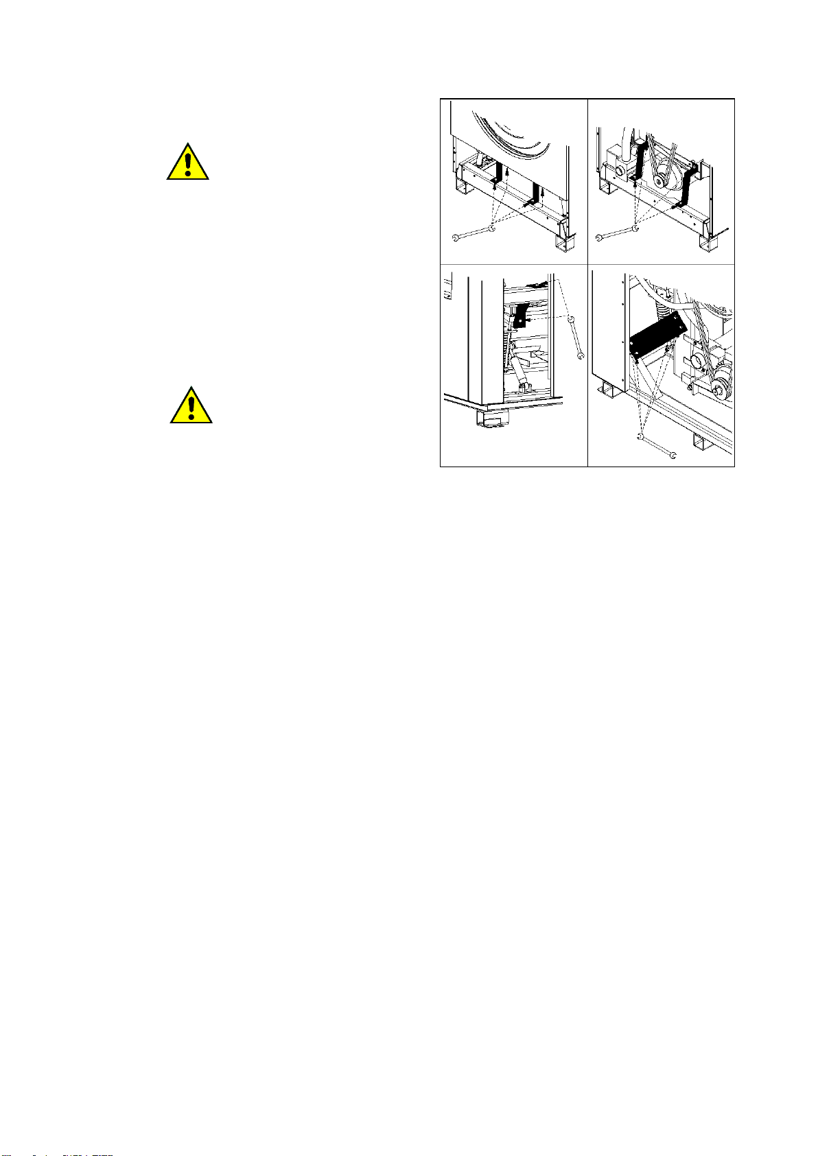
During the transport, the high spin washing
machines basement and cradle are blocked with
locks in order to avoid shock absorber stress.
ATTENTION!
Transport locks need to be removed once the
machine is positioned and before it is supplied.
To take off the transport locks, follow the next
instructions. Pictures indicate the lock type, not
the machine.
- Remove frontal and rear panels.
- Unscrew the bolts fixing the
transport locks.
- Remove the transport locks
- Mount again the panels in the original
position.
Each panel must be mounted again in the original
position before the machine is switched on.
When removed, the locks need to be kept and
used again each time the machine needs to be
moved.
5. MACHINE IDENTIFICATION
The sticker reporting the machine serial number,
model, power and technical characteristics
identifies the dryer. Be sure that the electrical,
hydraulic, steam, gas, compressed air
connections are complying with the sticker data.
Spare parts and/or services require the correct
model identification.
E170701X.01_ENG 16/04/18
8
If the sticker with serial number is tampered,
missed, removed or damaged in a way that does
not allow correct machine identification, the dryer
installation and service can be difficult and the
warranty automatically expires.
6. INSTALLATION AND POSITIONING
Installation must be by trained, qualified
personnel. Machine must be positioned on a flat
surface horizontally and in a stable way using the
adjustable feet at the dryer base. Feet can be
adjusted from outside, screwing and unscrewing
them until the dryer is correctly levelled.
In equipped models, the feet can be adjusted from
inside using a 5mm hexagonal key after the filter
door and the back panel have been opened.
Always check if the floor can bear the machine
weight written in the technical data sheet. The
machine load can be considered very static. To
calculate the dryer static load, the weight of the
wet linen to be loaded must be added to the dryer
net weight. Be sure the floor is clean and high
temperature resistant. For correct machine use,
working and service, leave at least 500 mm free
surface around the dryer.
The room temperature must be between +5ºC and
+40ºC.
Protection class is IPX4.
Relative humidity must be within 5% and 90%
(without condensation)
The room where the machine installed must have
enough incoming air ventilation. Please note: the
machine takes air from the room where it is
installed and expels the humid air from the drying
cycle to the outside.
Sizing the air intakes: refer to national normatives.
Consider a minimum of 9cm2/kW witha a minimum
surface of 150cm2. Remember that grates and
curtains reduce the flow of air.
The dryer must not be installed behind a door,
which can be closed with a key, a sliding door, or
a door with hinges mounted on the opposite side
to the tumble dryer.
Do not install or use a machine if it is damaged.
Do not install a machine in a position where the
door cannot be completely opened (a suitable kit
can be provided to change the door hinge from
left to right opening and vice versa)
ATTENTION!
Clean air must be assured to the machine; air
combined with chlorine, fluorine or other
solvent vapors must be avoided.
Do not use or stock near the machine
benzene, petroleum or other inflammable
stuffs otherwise fire or explosion may be
caused.
Keep near the machine a foam extinguisher,
which is periodically controlled in compliance
with the rules in force.
ATTENTION!
Machine CAN’T be installed on open air,
but in a CLOSED room, specifically built
and adhibited as a laundry.
E170701X.01_ENG 16/04/18
9
ATTENTION!
Check the cleaning of the drum.
Processing residues may be found in the
internal side of the drum.
ATTENTION!
In case of tilting machines foresee
necessary spaces to avoid the risk of
crush between the machine and the
elements in the installation room: other
machines, walls, roofs, doors and
windows (opened and closede) etc.
The amount of movement during the
phase of tilting can be founf in the
technical data sheet.
7. INSTALLATION: GAS HEATED MACHINES
SPECIFICATIONS
Independently from the capacity, every gas-
heated machine must be considered as a gas
equipment.
During the installation must be respected the
following rules:
-Territorial building and fire-prevention rules;
-Accident prevention rules;
-CENELEC rules /electric system);
-Rules about the combustible gas use
-Rules about gas system supplied by public
net or LPG gas
-Rules coming from the gas company
-Rules coming from the electricity company
-Other possible local rules.
Air inlet and ventilation openings can be closed
only if the opening condition is controlled and if
the flame of the gas-heated equipment has
opened air inlet and ventilation.
The room must be correctly ventilated, even when
the gas exhaust is mechanically operated, if the
nominal thermal pollution of this gas equipment
does not cause depression in the room. In this
way, a regular gas combustion and the complete
exhaust of the burn gas are guaranteed.
To dimension the air grating, please refer to the
data written on the machine technical sheet and to
the rules in force. In this way, a regular gas
combustion and the complete gas exhaust are
guaranteed.
Air inlet dimensions must comply with the
technical sheet requirements and with the subject
rules in force.
In case the dryer is supplied with liquid gas and is
installed in a basement, forced ventilation system
must be provided.
Data of gas are in paragraph 49.
ATTENTION!
Never install a gas-heated machine in the
same room where there are machines that use
solvents (example: dry cleaning machine).
This combination could produce dangerous
substances for the operator and it can cause
steel corrosion.
If a gas-heated machine and a machine using
solvents are installed in two separate rooms,
be sure that there is no possibility of air
exchange between these two rooms.
ATTENTION!
In case of machine equipped with a tilting
system, the machine must be fixed to the floor
using some screw anchors.
Machine must be installed perfectly
horizontally on a floor without elastic reaction.
ATTENTION!
In case of tilting machines, there are external
parts that move during the linen loading and
unloading steps.
For machine dimensions and machine-
required space during the movement, please
refer to the technical data sheet.
8. NOISE LEVEL
The air noise produced by the machine is
producing a continuous and weighted acoustic
pressure lower than 70 dB.
E170701X.01_ENG 16/04/18
10
9. ELECTRIC CONNECTION
Electric connections must be carried out by
qualified technicians and must comply with
local and National rules in force. Check if the
supply data corresponds to the data written on
the machine plate. (voltage tollerance ±10%,
frequency tollerance ±1Hz).
To connect the machine use a H05 VV –F cable
or superior and follow the data label and in the
technical data sheet to dimension it correctly.
Install before the machine an omni-polar
disconnecting device with interlocked padlock
(i.e.: a circuit breaker) which has a contact
opening that allows the complete disconnection in
case one of the conditions of the over tension III
category is verified. This device must comply with
the subject regulation in force.
Check the main switch; it must be in position “0”.
Open the electric supply door.
Pass the electric supply cable through the cable
holder supplied with the machine.
Before inserting the supply cable, verifiy that it
makes a dead neck lower than the entrance: in
this way eventual condensation drops, cannot get
in touch with electrical connections.
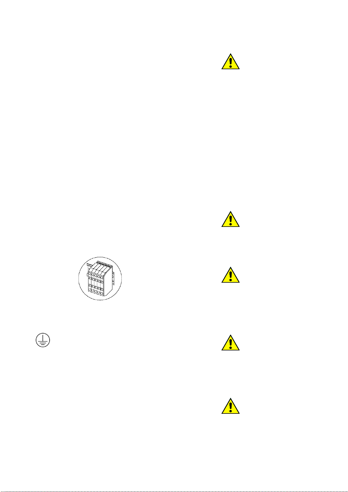
Electric supply cable connection must be done on
a series of marked terminal.
Following the kind of heating indicated on the
serial number plate, connect the cable to the
terminals, as indicated:
: Ground, color: yellow/green
L1, L2, L3: phase, color: brown
N: neutral, color: blue
In case of installation or replacement of the
supplying cable, the ground cable must be at least
5cm longer than the other cables. The electric
diagram is contained in an envelope, inside the
electric board.
On the back panel there’s an equipotential
born for the connection to be done according
to law,
ATTENTION!
Check the fan rotation direction: it must rotate in
the direction that allows the exhaust air discharge;
it means that the fan motor rotated in the direction
indicated by the arrow marked on the motor cover.
Check the correct connecting sequence of
phases.
The machine must be connected to an efficient
ground system: the supplier is not responsible in
case this connection is not operated in
compliance with the subject rules in force. Before
any maintenance, cut the electricity supply to the
machine: for the maintenance refer to the
machine electric diagram, which is inside the
machine; anyway, it can be retrieved at any
moment on manufacturer web site.
The minimum section for the electric cable is
indicated in the attached technical data sheet and
are expressed in mm2.
ATTENTION!
The technical data minimum sections can change
according to the connection length. In case the
cable is longer than 5 meters, the cable diameter
must be proportionally increased.
ATTENTION!
The machine connection must always be made
respecting the data written in the serial number
plate (power, supply tension, frequency).
For a different voltage from the one provided, ask
for more information to the manufacturer.
ATTENTION!
For a machine equipped with drum or fan speed
control, it means for machine equipped with
inverter, a protection by RCD type B device must
be provided (sensible to the current medium
value).
ATTENTION!
In case the machine is equipped with a supply
cable, and the cable is damaged, the
manufacturer must replace it or by the authorized
technical service; anyway only qualified personnel
can service the machine, in order to prevent any

E170701X.01_ENG 16/04/18
11
risk.
ATTENTION!
Before turning on the power supply of a
machine that suffered a therma rus, wait for
the evaporation of condensed humidity to
avoid damages to electronics.
10. EMERGENCY STOP IN SELF SERVICE
CONFIGURATION
Machines in a self service don’t have an
emergency button. The installer must supply an
emergency device connected to all the machines.
11. GAS CONNECTION
If the machine is gas heated, the necessary
connection with the distribution system must be
made: check the machine serial number plate
data, especially check supply gas pressure.
ATTENTION!
The maximum gas pressure admitted is
50mbar. To supply the gas with a higher
pressure, even for short time, may damage the
valve.
The gas distribution system must be realized in
compliance with the rules in force and it must
respect the sections and the pressure suitable for
the installed equipment, as per tables at the end
of this manual.
Look to the following picture: back to the machine
must be installed a rapid gas interceptor valve (1):
the gas cock must be near the dryer and in an
easily reachable position. The cock must comply
with the rules in force and must be an approved
model.
A low point pressure switch must be provided (2).
The connection to the gas system must be made
using a no-vibration joint (3); if flexible tubes are
used, these must be in stainless steel DIN 3384 or
DIN 3383.
The gas system must be realized in compliance
with the rules in force. Respect dimension of the
dryer gas-connection written in the technical data
sheet; this dimension must not be reduced.
The next picture shows how the machine should
be connected in case of gas cylinder with high
pressure. In this case, a two-step reduction
system is necessary; it must be realised in
compliance with the rules in force.
At first 1.5mbar governor must be connected after
the high pressure gas cylinder (1), after that a
safety valve with the appropriate dimension must
be installed (2).
The high pressure tube (3) is interrupted by an
interceptor cock (4) and then it follows protected
(5) below the compartments division area border.
Before entering the room where the machine is
installed, a second interceptor valve must be
provided and then a filter (6) and a second
governor (7) which brings the pressure to the
correct working value.
12. GAS CONNECTION: TIGHTNESS TEST
All the joints between system and dryer must be
tightness tested.
To make this test, use a leak finder spray;
otherwise, the joints can be covered with foamy
substances, which must not be corrosive. In both
cases, bubbles must not appear.

E170701X.01_ENG 16/04/18
12
ATTENTION!
It is forbidden to use free flame for tightness
test!
13. GAS CONNECTION: THERMAL POWER
Each dryer tested in the factory is prepared for a
kind of gas that is written in the sticker near the
serial number plate.
If the machine is predisposed for a gas that does
not correspond to the kind available in the
installation place, then it is compulsory to make
the dryer adaptation. In this case, the authorized
after sales center must be informed.
A dryer that is working with the expected thermal
power depends on the inlet pressure and the gas
calorific power, but also depends on the nozzle,
the gas pressure arriving to the nozzle and from a
correct supply of primary air.
The pressure of the gas arriving to the machine
must be included in the limits written on the gas
type tables. If the pressure is not included in the
limits written in this manual, the dryer cannot be
started.
If the verified gas pressure is different from the
table values, please contact the gas company or
the company that realized the gas system.
The GAS Lower Calorific Power, which must be
asked to the gas company, must correspond to
the one indicated in the technical data table.
14. GAS CONNECTION: GAS INLET
PRESSURE CONTROL
The inlet gas pressure must be controlled using a
digital or liquid measuring tool (resolution of 0.1
mbar at least).
- Close the interception device.
- Open the sealing screw on the pressure tube
gas valve connection indicated as “Pin”.
- Connect the manometer
- Open the interceptor device
- Start the dryer following the user instruction
- Check the inlet pressure, with the burner
working.
- Switch off the dryer.
- Close the interception device.
- Take off the monometre.
- Close the screw of the gas valve pressure
tube and control the tightness.
- Open the interceptor device and control test
the tightness.
The dryer must not be used if the gas pressure is
out of the limit shown in the reference table.
15. GAS CONNECTION: FINAL TEST
Once the connection works are completed, the
equipment and the installation must be tested. It is
necessary to test:
-That the connection are made respecting the
instructions written in this manual;
-That the safety rules and the laws about this
subject are respected;
-That gas connections are tightness tested.
Switch on the machine following the user manual
instructions controlling the burner lighting on and
the flame aspect.
Do a gas test with the volumetric method. Using
the gas regulator, control how much gas was used
in a fixed time unit: this value must be compared
with the values in the tables.
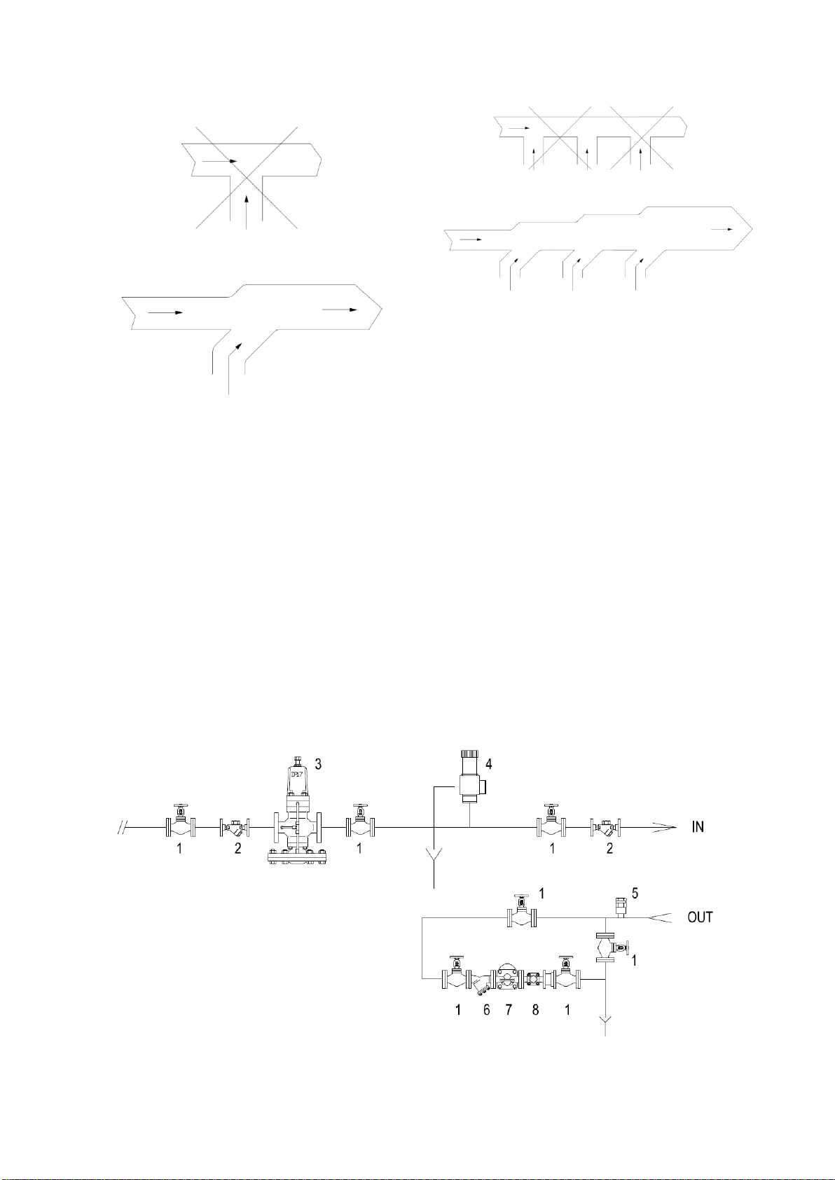
16. HUMID AIR AND BURN GAS EXAUST
The humid air and burns gas exhaust system
must be realized following the rules in force.
To avoid lack of humid air and noise, the exhaust
joints to the outside must be made tight with high
temperature resistant material (filler, putty,
silicone preparation).
To avoid leakage, don’t use spiral ducts: use
straight metallic and rigid tubes therefore. The
material used must be compatible with the
exhaust temperatures of the machine. Gas heated
tumble dryer are B22 equipment, it means they
are gas equipment which depend on an aired
room without any wind protection device with
blower behind the burning room.
Dryer burned gas must be brought outside
through a chimney.
Burnt gas and humid air pipe must be the shortest
possible one and it must be rising to the exhaust
chimney. To reduce load losses, don’t use curves
at 90 °, preferring two 45 ° curves.
A condenser drain must be provided in the lowest
point. This drain derivation must observe local
rules of water drain connection.
Te duct must resist to any crush. In case of a
manifold, don’t use "T" connections and consider
the correct value of the manifold section. If
necessary, increase the manifold section.
E170701X.01_ENG 16/04/18
13
The manifold for multiple machines can’t be done
for gas machines.
For machines with electric or steam heating it is
possible to foresee a collector: do not perform "T"
connections and consider the correct value of the
manifold section. If necessary, increase the
manifold section.
The dryer is equipped with a suction fan that
produces its typical noise while working.
To reduce the noise level, a muffler can be
installed on the drain (it can be found in a
specialized shop).
17. STEAM CONNECTION
Only for steam-heated fryers, personnel in
compliance with the national and local rules in
force must perform a connection. Steam must
satisfy the minimum requirement written in the
technical data sheet; all component in the system
must be certified. The steam system must be
realized following the below diagram:
E170701X.01_ENG 16/04/18
14
Elements are identified in the system as below:
1On –Off Valve;
2Filter;
3Pressure reducing valve (if necessary);
4Safety valve
IN) Machine steam exchanger inlet
ATTENTION!
In order to be efficient, the safety valve must
be of an adequate size to provide to the
maximum steam system rate.
5Vacuum breaker valves
6Filter
7Inverted bucket steam trap
8Flow indicator
OUT) Machine steam heater outlet
ATTENTION!
Drying productivity depends on the steam
heater efficiency.
Dryer can work within the steam pressure
range referred in the technical data sheet,
anyway lower is the pressure, poorer are the
machines performance. In order to avoid too
much longer drying time, the pressure should
be at least 5bar.
ATTENTION!
Open slowly the shut-off valve (1) to minimize
pressure shocks effects.
ATTENTION!
Electric valves MUST NOT intercept steam line
nor pneumatics for temperature adjust.
Machine damper already does the
thermoregulation. The use of valves shorten
the life of the exchanger and the warranty
automatically lapse.
ATTENTION!
Don’t touch steam inlet or outlet tube when
they are hot!
18. COMPRESSED AIR CONNECTION
Connection to a compressed air system is
necessary for some dryer models: check the
equipment data sheet.
Qualified personnel in compliance with national
and local rules in force must perform system.
Connections between system and dryer must be
tested tightly; it is suggested to use a leak finder
spray. In case of leaks, stop them.
19. HYDRAULIC CONNECTION: LOAD
The washing machines are equipped with
electrovalve for the cold and hot water loading (in
case it is requested, the machine is equipped with
a third electrovalve for hard water). Each water
inlet is identified, for connection quotes refer to
technical data sheet.
At the beginning of each hydraulic supply a gate
valve must be provided to cut the water supply to
the machine at any moment, in case of
emergency or in case of service.
At the beginning of each water inlet an inspect
filter must be provided. It is necessary, also, to
control the machine inlet valve filter after a short
time of use, overall the hydraulic system is old or
not used from a long time.
ATTENTION!
All the inlet valve must always be connected!
If in the supply system it is not available the
hot water, connect cold water also to the inlet
valve called “HOT WATER”.
When more washing machine are connected to
the same water line, the water line must have a
diameter sufficient to grand a water flow enough
to supply all the machine in case all of them are
loading water.
A minimum pressure of 0,4 atm is necessary to
load the water: if the supplied pressure is lower,
the water loading time are longer.
Maximum water loading pressure is 8 Atm (the
minimum and maximum values are taking in
E170701X.01_ENG 16/04/18
15
consideration all the kind of valve mounted on the
different machine size).
20. HYDRAULIC CONNECTION: DRAIN
The electric drain valve used are a normally open
kind, it means that the water is drained in case of
black out.
In case of more washing machines connected to
the same drain line, it must be enough to allow the
correct water flow in case all the machines are
draining water at the same time.
Drain collector must avoid that the water drained
by one machine enter in the next one.
The washing machine drain is for gravity, the
drain tube must not present sinking or counter
slope. A 2% slope must be provided to allow a
correct water flow.
The drain system must satisfy the local or national
laws and regulation in force.
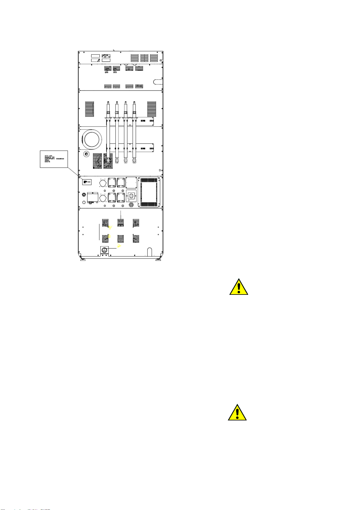
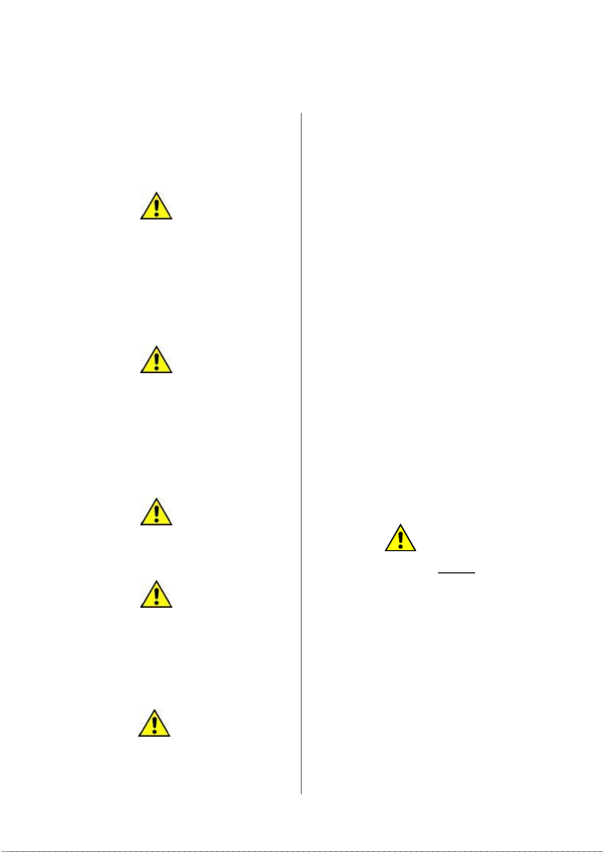
21. MACHINE DESCRIPTION
The dryer is characterized by some elements that
must be known before using the machine.
The point no. 1 identifies the door of the washing
machine..
The point no. 2 identifies the door of the dryer.
The point no. 3 identifies emergency mushroom (if
present).
The point no. 4 identifies the humid air exhaust
(always) and the burn gas exhaust (in case of
gas-heated machines).
The point no. 5 identifies the electronic connection
box and apart of the electric system. Only
competent and specialized personnel are allowed
to access to the electric board.
The point no. 6 identifies the peristaltic pumps.
ATTENTION!
Air intakes on the machine back must be
always free. The air passage must not be
limited in any way.
22. MASCHINE START AND FINAL TEST
Once the machine is installed, and all connections
are made, it must be started following the
provided instructions. Each machine part must be
tested: start a program and check at least one
complete program. The machine must be fully
loaded and, in case of high spin machines, the
unbalance end switch position must be controlled.
23. LANGUAGE CHANGE
When the machine is switched on for the first
time, interface language could be different from
the one wished by the user.
The following procedure explains how to change
the interface language.
Touch the icon “MENU” of the home page.

E170701X.01_ENG 16/04/18
16
The display shows:
Touch the icon “PARAMETERS”, the display
shows:
Digit the code “111111” and the display shows:
Touch the icon MODIFICA and scroll the menu of
the available languages using the keys “<<” and
“>>”. When the whished language appears on the
screen, confirm touching the icon “OK”.
Exit the configuration menu touching the icon
“HOME” as many time as necessary to reach the
home page.
24. REMOTE ASSISTANCE SERVICE
ACTIVATION
In case of models equipped with the remote
assistance system, the connection to the service
server must be activated. In order to do it, check
the instructions sent with the machine.

E170701X.01_ENG 16/04/18
17
25. HOW TO PREPARE THE LINEN: WASHING
MACHINE
Machine must be loaded on the base of the serial
number plate: it must not be loaded with a weight
higher than the one written in the technical data
sheet or in the serial number plate.
Before to choose the most suitable program, the
linen need to be sorted into groups homogeneous
for fibers and fabrics, in order to have a uniform
washing for the whole load.
Before to put the linen into the washing machine,
be sure that the linen label is authorizing the
machine washing; always stick to linen
manufacturer indication.
Here below the meaning of the most common
International symbols:
Maximum temperature: 70°;
Mechanical action: midle.
Maximum temperature: 60°C;
Mechanical action: soft
Maximum temperature: 40°C;
Mechanical action: very soft
Only hand washing
Do not clean with water
26. HOW TO LOAD THE MACHINE AND CLOSE
THE DOOR
The machine must be loaded following the
indication given in the serial number plate.
The label is stuck on the machine back.
ATTENTION!
Machine must be loaded with linen, which is the
most homogeneous possible. The weight of the
loaded linen must not be higher than the one
indicated in the technical data sheet and in the
serial number sticker.
Before to load the linen, be sure that the drum is
completely empty. When the machine is loaded,
close the door.
ATTENTION!
Be sure that no linen parts are taken between the
door and the machine front panel, while the door
is going to be closed.
In case of machine without door handle, just press
the door against the machine until it is locked.
In case of machine with handle or motorized door
lock, the door must just set ajar the machine front,
in this way the closing pin enters in the correct
position on the machine front.
When the machine is started the computer will
give the command to lock the door.
ATTENTION!
In case of barrier washer (double door): before to
close the external door, be sure that the drum
door was correctly closed as explained in the
notice supplied with the machine.
In case the inside door was not correctly
closed, the program MUST NOT be started.
Be sure that the operators perfectly
understood how to close the inside door!
27. DOOR MANUAL OPENING
While the cycle is running, it could be necessary
to open the door manually, without using the
unlock function of the touch screen.
ATTENTION!
Before to open manually the door, cut the
electricity supply to the machine using the
main switch.
E170701X.01_ENG 16/04/18
18
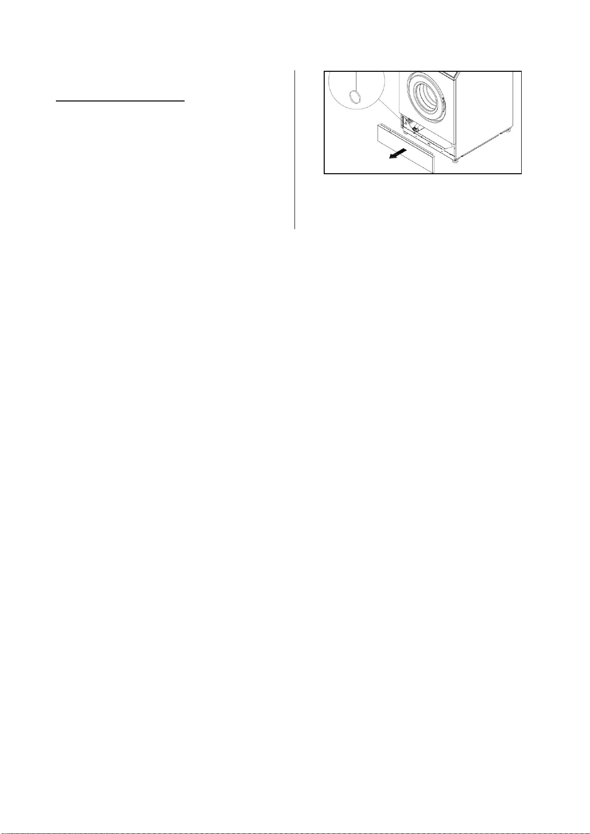
Machine with impulse closing
Open the below panel (the one shown in the
picture). To unlock the door, pull the lanyard with
the small ring.

E170701X.01_ENG 16/04/18
19
Machines with motorized door lock
Remove the small plug (1) and insert the unlocking lever (2) in the door lock as show in the picture (on the
above edge). The lever must be correctly positioned!
Turn the lever upward until the mechanism clicks.
When the motorize door locking is manually opened, the mechanism alignment procedure must be done as
soon as the electricity is came back.
Touch “MENU”
Touch “PARAMETERS”
Touch: “111111”
Touch “<<”
Touch “MODIFY”
confirme with “OK”
1
2
RIPOSIZIONAMENTO
BLOCCO PORTA
RIPOSIZIONAMENTO
BLOCCO PORTA

E170701X.01_ENG 16/04/18
20
ATTENTION!
Before to supply again energy to the machine, all the protection must be placed again in the original
position.
28. HOW TO SWITCH ON THE MACHINE
Switch on the main switch, which supply the
machine.
In case of steam heated machines: open the
steam gate valve to allow the steam to enter.
To limit water hammering cases, the valve must
be open slowly passing from the close position to
open position in 1 minute time.
The emergency stop button must be in rest
position; control that the emergency stop was not
activated during the transport or before the
machine was switched off last time.
Before to start the machine always check the
safety system (refer to the related paragraph).
When the machine is switched on, the software
version, as well as its release date, appear on the
screen for a while.
The software loading could take a minute time,
more or less.
The display shows:
Load the machine and close the door following the
instruction given in the previous paragraphs.
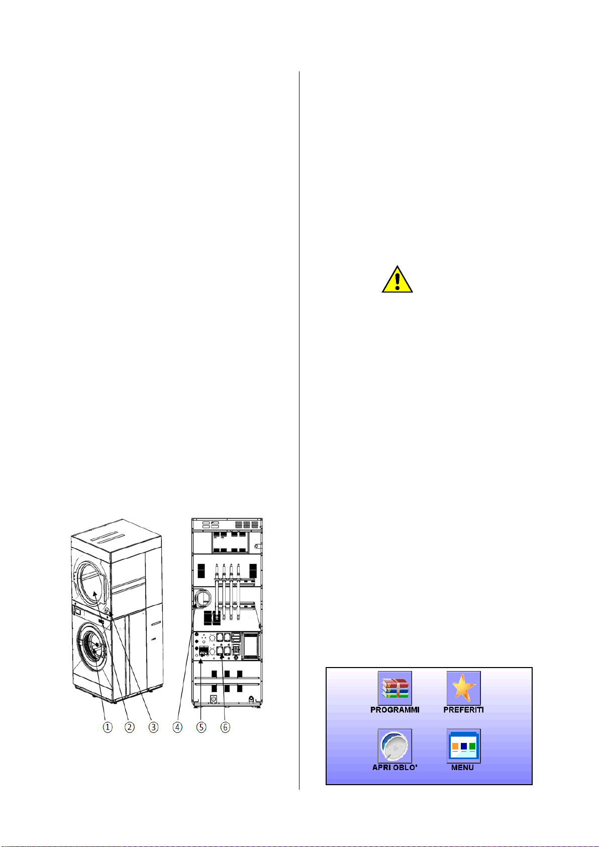
29. HOW TO SELECT A PROGRAM
When the machine is loaded and the door is
closed, the touch screen shows:
Touch the icon “PROGRAMS” to display the
program list.
Table of contents
Other Imesa Industrial Equipment manuals


