imilab CMSXJ33A User manual

Read this manual carefully before use,
and retainit for future reference.
EN FRDE ESIT RURU PL TR
IMILAB
Video Doorbell Set
UserManual

CONTENTS
English 01-11
12-22Deutsche
45-55Español
34-44Italiano
23-33Français
56-66Pусский
67-77Polski
78-88Türkçe

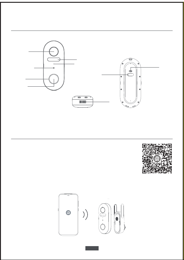
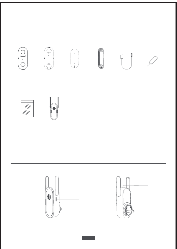
Product overview
Hub
Status LED
MicroSD
Card Slot
Speaker
Reset Button
Power
Getting started
Doorbell
Detaching
Pin
IMILAB
Video Doorbell
Mounting
Bracket
Screw Hole
Positioning Card
15° Mounting
Wedge
For video doorbell & hub installation
Mounting
Screws
and Anchors
Micro-USB
Charging Cable
EN-01
IMILAB
Smart Hub
EN-02
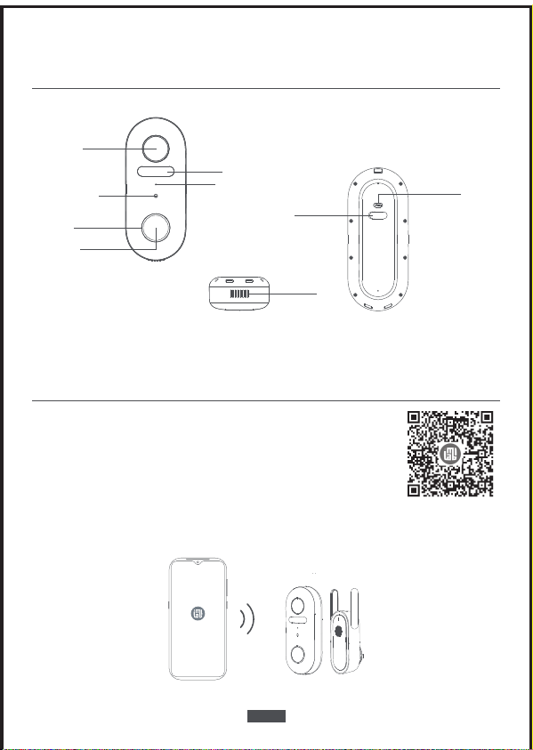
Video Doorbell
Microphone
Light
sensor
Speaker
Camera Lens
Micro USB
Charging Port
Doorbell Button
LED Ring
Motion Sensor
SYNC Button
Setting up the system
Download the app and set up the system
1. Download the Imilab Home APP from the app store (ios devices) or
google play (Android devices).
2. Sign up for a imilab home account , then follow the onscreen instructions to complete
the setup.

EN-03
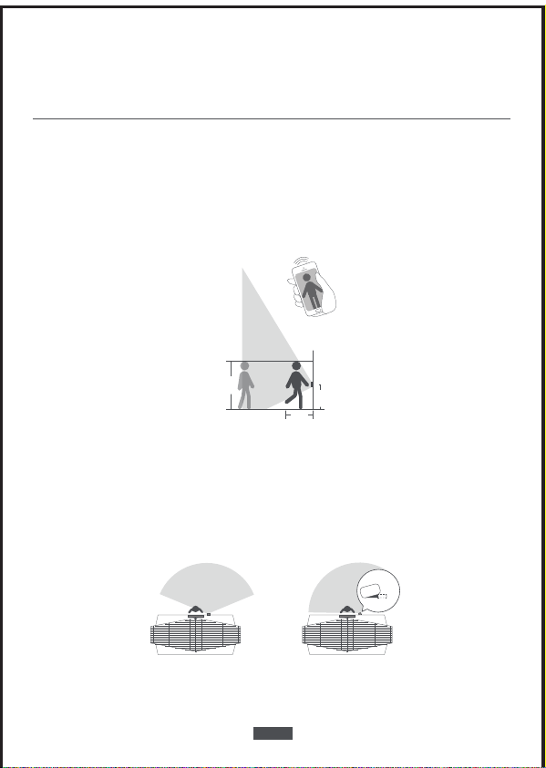
Mounting the video doorbell
Find a Mounting Spot
Take the video doorbell to your front door and check the live view on the App at the same
time. Find a location where you can get the desired field of view.
Consider the below factors:
1.If you want to place the doorbell close to a side wall, make sure the wall doesn’t show
up in the field of view. Otherwise IR light will be reflected and night vision will become
blurry.
1.2m
(48”)
1m
(40”)
0.3m
(12”)
1.76m
(5‘9”)
2.If you are drilling the mounting holes for the first time, the recommended mounting
height is 48”/1.2 m from the ground.
3.Use the 15°mounting wedge as a supplementary mounting bracket if you wish to see
more on a specific side.
Door Video Doorbell
Without 15° Mounting wedge
(Overlook verb)
Door Video Doorbell
With 15° Mounting wedge
(Overlook verb)
15°

EN-04
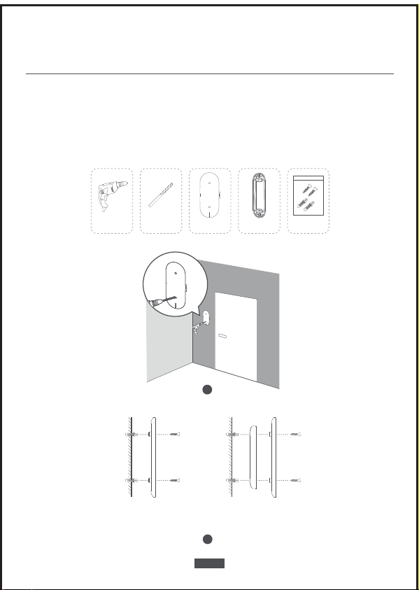
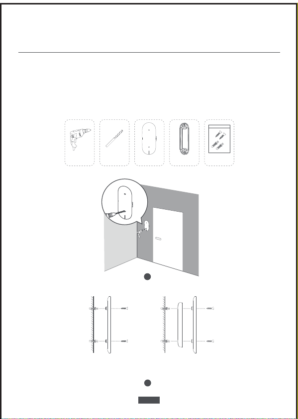
Place the Screw Hole Positioning Card against the wall to mark the position.
Mount the Doorbell on a Wooden Surface
If you’re mounting the doorbell on a wooden surface, you don’t need to pre-drill pilot
holes. Use the provided screws to secure the Mounting Bracket on the wall, The Screw Hole
Positioning Card indicates the position of the screw holes. What is required: Screwdriver,
Mounting Bracket, 15° Mounting Wedge , Mounting Screws and Anchors.
Screwdriver
(not provided)
Mounting Bracket 15° Mounting
Wedge
Mounting Screws
and Anchors
Wall Mounting
Bracket
Without 15° Mounting wedge
Wall Mounting
Bracket
Mounting
Wedge
With 15° Mounting wedge
EN-05
Mount the Doorbell on Surfaces Made Out of Hard Materials
1.If you‘re mounting the doorbell on a surface made out of hard materials, like brick,
concrete, stucco, drill 2 holes through the Screw Hole Positioning Card with a 15/64”
(6mm) drill bit.
2.Insert the provided anchors,and then use provided long screws to secure the Mounting
Bracket on the wall.
What is required: Power Drill, 15/64”(6mm) Drill Bit, Mounting Bracket, 15° Mounting
Wedge , Mounting Screws andAnchors.
Power Drill
(not provided)
15/64”(6mm)
Drill Bit
Mounting Bracket 15° Mounting
Wedge
Mounting Screws
and Anchors
1
Wall Mounting
Bracket
Without 15° Mounting wedge
Wall Mounting
Bracket
Mounting
Wedge
With 15° Mounting wedge
2
EN-06
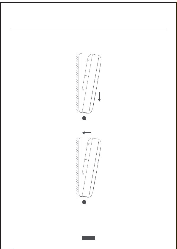
Mount the Doorbell
Align the doorbell on the bottom and then snap it on top.
Press it down until it clicks into place.
You’re all set!
If you want to detach the doorbell or recharge it, please refer to the following sections.
1
2

Charging the doorbell
5V USB Charger
Detach the Doorbell
1.Use the doorbell detaching pin provided if you wish to detach the doorbell from the
Mounting Bracket.
2.Press and hold the hole on the top of the doorbell and then lift its bottom to take it o.
What is required: Doorbell Detaching Pin.
Doorbell
Detaching Pin
1 2
EN-07
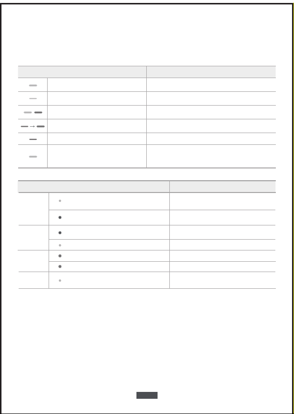
Explanations for LEDS
Hub LED Status
Blinking blue
Blue and orange
flashes alternately
Solid blue
Waiting for connection
Network connection is successful / connected
Network connection is failure
Status
Solid orange A firmware update is in progress
Press and hold the button
for 10 seconds, until the
LED blinks blue
During the reset process, the hub will restart
Blinking orange Waiting for doorbell to connect
Power
on/o
You will hear the power-on music
you will hear the power-o music
Press and hold the sync button for 2 seconds
until the blue light becomes to solid
Press and hold the sync button for 8 seconds
until the LED blinks green
Use USB to charge the
doorbell
Solid green
Charging
continuous blinking green
Fully charged
Doorbell
charging
Video Doorbell LED Status Status
Orange blinks once PIR detects motion
PIR continues to detect motionOrange blinks continuously
PIR
detection
sensitivity
adjustment
Press the doorbell button, then doorbell
indicator light will blink blue
Both the outdoor doorbell
and the indoor hub will ring
Doorbell
function
EN-08

Specifications
Safety statement
Name: IMILAB Video Doorbell Model: CMSXJ33A
Resolution: 2560x1440 Aperture: F1.6
Item Dimensions: 60 x 33 x 142 mm Power Input: 5 V 2 A
Operating Temperature: -20 °C ~ 50 °C FCC ID:2APA9-CMSXJ33A
Name: IMILAB Doorbell Hub
Model: CMWG33B
Power Input: 100-240V~,50/60hz,0.3A MAX
Item Dimensions: 57 x 34 x 105mm
Operating Temperature: -10 °C ~ 45 °C
Expandable Memory: MicroSD card(up to 64 GB)
Wireless Connectivity: Wi-Fi IEEE 802.11 b/g/n 2.4 GHz
FCC ID:2APA9-CMSXJ33B
The suitable operationg temperature range for this product is between -20℃~50℃.
Don't use the product in an environment with temperatures above or below the
specified range.
When charging, the operating tempreture range for this product is between 0°C~ 45°C.
Don't charge the product in an environment with temperatures above or below the
specified range.
Using the product in a low tempreture environment or charging status will aect its
standby time. The actual standby time is related to the user's environment and habbit.
To improve the product's performance, please do not place the video doorbell lens
facing or next to a reflective surface, such as glass windows/doors and white walls,
which will cause the image to appear overly bright inareas close to the video doorbell
and darker in areas further away, or cause the video doorbell to produce white images.
Please install the product in areas with Wi-Fi reception, and try to place the device
where the Wi-Fi signal is strong. In addition, please keep the security video doorbell
away from metal structures, microwave ovens, or other locations where signal strength
may be impacted.
Don't replace the battery in video doorbell yourself—if not properly replaced, there is a
danger of explosion.
Battery (battery pack or batteries) must not be exposed to sunlight, fire, or similar
overheating conditions.
This product is a low power consumption video doorbell with battery built-in. Don't use
Real-Time Monitoring feature for long time when charging, in order to avoid battery life
loss.
Do not use the device in the environment at too high or too low temperature, never
expose the device under strong sunshine or too wet enviroment.
Precautions
EN-09

All products bearing this symbol are waste electrical and electronic equipment
(WEEE as in directive 2012/19/EU) which should not be mixed with unsorted
household waste. Instead, you should protect human health and the environment
by handing over your waste equipment to a designated collection point for the
recycling of waste electrical and electronic equipment, appointed by the
government or local authorities. Correct disposal and recycling will help prevent potential
negative consequences to the environment and human health. Please contact the installer
or local authorities for more information about the location as well as terms and
conditions of such collection points.
WEEE Information
FCC Statement
Changes or modifications not expressly approved by the party responsible for compliance
could void the user's authority to operate the equipment. This device complies with Part
15 of the FCC Rules.
Operation is subject to the following two conditions:
(1) This device may not cause harmful interference, and
(2) This device must accept any interference received, including interference that may
cause undesired operation.
Note: This equipment has been tested and found to comply with the limits for a Class B
digital device, pursuant to Part 15 of the FCC Rules. These limits are designed to provide
reasonable protection against harmful interference in a residential installation. This
equipment generates, uses, and can radiate radio frequency energy, and if not installed
and used in accordance with the instructions, may cause harmful interference to radio
communications.
However, there is no guarantee that interference will not occur in a particular installation.
If this equipment does cause harmful interference to radio or television reception, which
can be determined by turning the equipment o and on, the user is encouraged to try to
correct the interference by one or more of the following measures:
-Reorient or relocate the receiving antenna.
-Increase the separation between the equipment and receiver.
-Connect the equipment into an outlet on a circuit dierent from that to which the receiver
is connected.
-Consult the dealer or an experienced radio/TV technician for help.
FCC 20cm Statement: This equipment complies with FCC radiation exposure limits set forth
for an uncontrolled environment. This equipment should be installed and operated with
a minimum distance of 20cm between the radiator & your body. This transmitter must not
be co-located or operating in conjunction with any other antenna or transmitter.
EN-10

Hereby, Shanghai Imilab Technology Co., Ltd. declares that the radio equipment type
IMILAB Video Doorbell is in compliance withDirective 2014/53/EU.
Hereby, Shanghai Imilab Technology Co., Ltd. declares that the radio equipment type
IIMILAB Doorbell Hub is in compliance with Directive 2014/53/EU.
The full text of the EU declaration of conformity is available at the following internet
address: https://www.imilabglobal.com/pages/eu-declaration-of-conformity
EU Declaration of Conformity
EN-11
Produktübersicht
Hub
Status LED
SD-Kartenschlitz
Lautsprecher
Rücksetzungstaste
Strom
Inbetriebnahme
Türklingel-Trennstift
IMILAB
Video-Türklingel
Befestigungshalterung
Schraubloch
-Positionskarte
15° Befestigungskeil
Für Video-Türklingel- & Hub-Montage
Befestigungsschrauben
und Dübel
Micro-USB
-Ladeanschlusskabel
DE-12
IMILAB
Smart Hub
DE-13
Video-Türklingel
Mikrophon
Lichtsensor
Lautsprecher
Kameraobjektiv
Micro-USB
-Ladeanschluss
Türklingelknopf
LED-Ring
Bewegungssensor
SYNC Taste
Einstellen des Systems
Laden Sie die App herunter und stellen Sie das System ein
1. Laden Sie die Imilab Home App vom App Store (IOS Geräte) oder
Google Play (Android Geräte) herunter.
2. Melden Sie sich in einem Imilab Home Account an und folgen Sie den Bildschirman-
weisungen um das Einstellen zu vollenden.
DE-14
Befestigung der Video-Türklingel
Finden Sie einen Befestigungspunkt
1.2m
(48”)
1m
(40”)
0.3m
(12”)
1.76m
(5‘9”)
Tür Video-Türklingel
Ohne 15°-Befestigungskeil
(Aufsicht)
Tür Video-Türklingel
Mit 15°-Befestigungskeil
(Aufsicht)
15°
2. Wenn Sie die Befestigungslöcher zum ersten Mal bohren, so liegt die empfohlene
Befestigungshöhe in einer Höhe von 48 Zoll/1,2 m vom Boden.
3. Verwenden Sie den 15°-Befestigungskeil als eine zusätzliche Befestigungshalterung,
wenn Sie auf einer bestimmten Seite mehr sehen möchten.
Nehmen Sie die Video-Türklingel zur Vordertür und prüfen Sie gleichzeitig die
Live-Ansicht auf der App. Finden Sie einen Ort, an dem Sie das gewünschte Blickfeld
erhalten.
Berücksichtigen Sie die folgenden Faktoren:
1. Wenn Sie die Türklingel in der Nähe der Seitenwand befestigen möchten,
vergewissern Sie sich, dass die Wand nicht im Blickfeld erscheint. Andernfalls wird das
Infrarotlicht reflektiert und die Nachtsicht verschwimmt.

DE-15
Halten Sie die Schraubloch-Positionskarte gegen die Wand, um die Position zu
kennzeichnen.
Befestigung der Türklingel auf einer hölzernen Oberfläche
Schraubenzieher
(nicht enthalten)
Befestigungshalterung 15°-Befestigungskeil Befestigungsschrauben
und Dübel
Wand Befestigungshalterung
Ohne 15°-Befestigungskeil
Wand Befestigungshalterung
Befestigungskeil
Mit 15°-Befestigungskeil
Wenn Sie die Türklingel auf einer hölzernen Oberfläche befestigen, müssen Sie keine
Vorbohrungen durchführen. Verwenden Sie die bereitgestellten Schrauben, um die
Befestigungshalterung an der Wand zu sichern, die Schraubloch-Positionskarte gibt die
Position der Schraublöcher an. Was wird benötigt: Schraubenzieher, Befestigungshalter-
ung, 15°-Befestigungskeil, Befestigungsschrauben und Dübel.
DE-16
Befestigung der Türklingel an Oberflächen aus harten Materialien
Bohrmaschine
(nicht enthalten)
Bohreinsatz von
15/64 Zoll (6mm)
Befestigungshalterung 15°-Befestigungskeil Befestigungsschrauben
und Dübel
1
Wand Befestigungshalterung
Ohne 15°-Befestigungskeil
Wand Befestigungshalterung
Befestigungskeil
Mit 15°-Befestigungskeil
2
1. Wenn Sie die Türklingel auf einer Oberfläche aus harten Materialien befestigen, wie z.
B. Ziegelsteine, Beton, Gips bohren Sie 2 Löcher durch die Schraubloch-Positionskarte
mit einem Bohreinsatz von 15/64 Zoll (6mm).
2. Führen Sie die mitgelieferten Dübel ein und verwenden Sie dann lange Schrauben,
um die Befestigungshalterung an der Wand zu befestigen.
Was wird benötigt: Bohrmaschine, Bohreinsatz von 15/64 Zoll(6mm), Befestigungshal-
terung, 15°-Befestigungskeil, Befestigungsschrauben und Dübel.

DE-17
Befestigung der Türklingel
Richten Sie die Türklingel unten aus und lassen Sie sie dann oben einschnappen.
Drücken Sie sie herunter, bis sie einrastet.
Sie sind fertig!
Wenn Sie die Türklingel entfernen oder aufladen möchten, lesen Sie bitte die folgenden
Abschnitte
1
2

Aufladen der Türklingel
5V-USB-Ladegerät
Entfernen der Türklingel
Türklingel-Trennstift
1 2
DE-18
1. Verwenden Sie den mitgelieferten Türklingel-Trennstift, wenn Sie die Türklingel von
der Befestigungshalterung entfernen möchten.
2. Drücken und halten Sie das Loch auf der Oberseite der Türklingel und heben Sie dann
ihre Unterseite hoch, um sie abzunehmen. Was wird benötigt: Türklingel-Trennstift
This manual suits for next models
1
Table of contents
Languages:
Popular Accessories manuals by other brands


Link
Link CAN Gauge user manual

Polaroid
Polaroid Play+ 3DPen user guide

Endress+Hauser
Endress+Hauser Cleanfit P CPA472D operating instructions

Acson
Acson AAD13A Operation manual

Docking Drawer
Docking Drawer Docking Drawer Series Electrical Planning Guide

PCB Piezotronics
PCB Piezotronics IMI SENSORS HT640B00 Installation and operating manual

TeraBee
TeraBee TeraRanger Evo Thermal series user manual

Gared
Gared MINI-EZ Installation, operation and maintenance instructions

Cerlic
Cerlic ITX 20 manual

Pavone Sistemi
Pavone Sistemi UWT6008 Technical manual

ORIGYN
ORIGYN autoSPRITZ OAS1aw user manual

PCB Piezotronics
PCB Piezotronics M260A03 Installation and operating manual