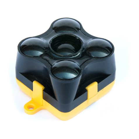
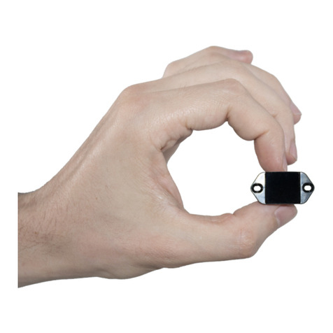
TeraBee TeraRanger Evo Thermal series User manual

User Manual for
TeraRanger Evo Thermal with:
USB and UART backboards
Technical support: [email protected]

Table of contents:
1 Introduction 3
2 Mechanical integration 3
2.1 Mechanical design 5
2.2 Sensor handling during system assembly 6
3 USB backboard use 6
3.1 Graphical User Interface 6
3.1.1 Prerequisites 6
3.1.2 Basic Operation 7
4 UART backboard use 12
4.1 UART interface 12
4.2 Backboard LEDs 13
4.3 Electrical characteristics 14
5 Communication 14
5.1 UART protocol information 14
5.2 USB protocol information 14
5.3 Commands 15
5.4 UART / USB output format 15
5.5 CRC32 checksum reconstruction 17
6 Compliance 18
Appendix 19
A.1 CRC validation 19
A.1.1 How to calculate CRC8 checksum for Evo Thermal 19
A.1.2 How to calculate CRC32 checksum for Evo Thermal 19
A.2 Sample code 20
Copyright © Terabee 2018
Terabee, 90 Rue Henri Fabre
01630, St Genis-Pouilly, France (next to CERN)
2/20

1Introduction
The purpose of this document is to give guidelines for use and integration of the TeraRanger
Evo Thermal sensors with (a) UART backboard, and/or (b) USB backboard using these
standard communication interfaces.
1.1 About TeraRanger Evo Thermal
TeraRanger Evo Thermal is the thermographic addition to the TeraRanger Evo sensor
family. It provides a 32x32 pixel resolution in a compact and affordable design, available in 2
versions.
Figure 1. TeraRanger Evo Thermal two versions
Evo Thermal 90 benefits from a wide 90 degree Field-of-View for monitoring larger areas.
The sensor also has a smaller and lighter design (10 grams).
Evo Thermal 33 offers longer range, higher sampling rate (14Hz) and a more detailed
thermal image because of the narrower Field-of-View.
By using passive infrared thermal technology, Evo Thermal sensors operate in a broad
range of conditions including indoors, outdoors, sunlight, complete darkness and poor
visibility. Because thermal data does not reveal identity, personal privacy is at all times
protected.
To learn more about sensor technical specifications, please see TeraRanger Evo Thermal
Specification sheet.
2Mechanical integration
The mechanical design of the main sensor module (black) allows easy assembly to its
backboard (yellow) using a simple ‘clip-in’ technique. When you clip the two together, ensure
there is no visible gap between the black and yellow parts. The yellow backboard has two
mounting holes for final installation. Please reference Figure 2 for visual instructions.
Copyright © Terabee 2018
Terabee, 90 Rue Henri Fabre
01630, St Genis-Pouilly, France (next to CERN)
3/20
Figure 2. TeraRanger Evo two-part design
When choosing a place for mounting, please consider the following recommendations:
● Choose a place which is in accordance with the optical constraints listed below
● Mounting close to sources of heat or strong electromagnetic fields can decrease the
sensing performance
● Do not mount anything directly in front of the sensor or in a cone of approximately
±90° around the central optical axis of the sensor
● Please consider that dust, dirt and condensation can affect the sensor’s performance
● To obtain a correctly positioned (not inverted or rotated) thermal image, please mount
the sensor with the USB or UART connector pointing left (if facing sensor’s lens). See
Figure 3 for visual instructions. This also applies when hand-testing Evo Thermal via
our graphical user interface (ref. Section 3.1.2).
Figure 3. Module orientation for correct thermal image. Evo Thermal 33.
Copyright © Terabee 2018
Terabee, 90 Rue Henri Fabre
01630, St Genis-Pouilly, France (next to CERN)
4/20

2.1Mechanical design
Figure 4. Evo Thermal 90 external dimensions
Figure 5. Evo Thermal 33 external dimensions
Copyright © Terabee 2018
Terabee, 90 Rue Henri Fabre
01630, St Genis-Pouilly, France (next to CERN)
5/20

2.2Sensor handling during system assembly
During assembly and integration, please observe all common ESD precautions. All optical
surfaces (sensor front) should be kept clean and free from contact with chemicals.
3USB backboard use
The USB backboard comes with a standard Micro-USB connector.
3.1Graphical User Interface
A free Graphical User Interface (GUI) is available, providing an easy way to visualize the
data from your TeraRanger Evo Thermal sensor. This is useful for demonstration, testing
purposes and checking some of the basic parameters of the sensor. It also provides an
option to easily record thermal images, export raw data and upgrade the firmware running on
the device.
The GUI is available for download here: GUI Download. (See “Download” section of the
TeraRanger Evo Thermal product page).
3.1.1
Prerequisites
For usage on Windows 7 and Windows 8, please download the Virtual COM Port driver from
http://www.st.com/en/development-tools/stsw-stm32102.html and follow the ”ReadMe file”
instructions given by the installer. After successful installation, unplug the interface for a
few seconds, and plug it back in. The virtual COM port should now be available on your PC.
Users of Windows 10 do not need to download this driver as the built in Windows driver is
recommended.
Copyright © Terabee 2018
Terabee, 90 Rue Henri Fabre
01630, St Genis-Pouilly, France (next to CERN)
6/20

3.1.2
Basic Operation
During installation of the GUI, you might receive a notification from Windows about an
unknown application trying to start (Figure 6). In the “Windows protected your PC” screen
select More info > Run anyway to proceed with Evo Thermal GUI installation and please be
advised that running this application will not put your PC at risk.
Figure 6. Windows protection screen during installation
After successful installation, make sure your TeraRanger Evo Thermal is connected to a
USB port on your computer. In the GUI select File > Connect (Ctrl+C). You will immediately
see thermal data displayed in a 32x32 pixel color map (Figure 7) on the left side of the GUI.
For the purposes of this instruction, Evo Thermal 33 sensor has been used.
Figure 7. Graphical user interface: home screen
Copyright © Terabee 2018
Terabee, 90 Rue Henri Fabre
01630, St Genis-Pouilly, France (next to CERN)
7/20

By default, on each new connection, temperature readings in the GUI will be displayed in
Celsius units. To modify measurement units in real-time, select Data > Temperature Units
and choose to present data also in Kelvin and Fahrenheit (Figure 8).
Figure 8. Setting temperature units in GUI
On the right side of the depth map you will find a color vs temperature scale. By default the
scale will be automatically adjusted depending on the highest and lowest temperature values
detected in the sensor’s Field-of-View at time of data capture. To set custom temperature
bounds, in the Scaling field (Top right) select Manual and you should now be able to input
minimum and maximum temperature bounds. Select “Apply limits” to apply changes, and
the scale will adjust according to the set values. To switch back to automatic temperature
scaling, select Auto. See Figure 9 for visual instructions.
Figure 9. Scaling field
The GUI also offers the option to display the temperature readings in one of 4 colormaps. To
do this, in the Scaling field, select Colormap and from the dropdown menu choose between
the following colormaps: Iron, Rainbow, High Contrast and White hot. The temperature
map will change automatically once a colormap is selected (Figure 10)
Copyright © Terabee 2018
Terabee, 90 Rue Henri Fabre
01630, St Genis-Pouilly, France (next to CERN)
8/20

Figure 10.Colormaps: Iron (top left), Rainbow (top right),
High Contrast (bottom left), White hot (bottom right).
On the main interface, you will also find basic parameters of the Evo thermal sensor
adapting in real-time to the measuring environment. These values include:
● Minimum temperature value (Min),
● Mean temperature value (Mean),
● Maximum temperature value (Max),
● Proportional to Absolute temperature (PTAT).
A visual 2-axis graph on the main interface of the GUI illustrates temperature patterns in real
time over all 1024 pixels of the Thermal sensor (Figure 11). This provides a quick
temperature spread overview of objects measured within the sensor's Field-of-View.
Copyright © Terabee 2018
Terabee, 90 Rue Henri Fabre
01630, St Genis-Pouilly, France (next to CERN)
9/20

Figure 11. Real-time temperature distribution of pixels
Evo Thermal GUI also allows to set temperature limits and enable warning notifications once
thresholds are breached. In the Temperature alarm setup section, first select upper and
lower temperature limits and click Apply limits to confirm. Next, choose the method for
triggering the alarm: (1) based on mean temperature or (2) heat measured at the center of
target. An option for adding an audio alert is also available. After all parameters are set, click
Start to initiate the alarm function (Figure 12).
Figure 12. Setting alarm for temperature breach
At the bottom of the GUI, Toggle center measurement feature enables to measure
temperature of the central part in the thermal map. A rectangular crosshair will be drawn in
the center of the thermal map, encompassing 4 pixels. Simultaneously, a small text field will
appear on the top left corner to display a temperature value, which is an average of the 4
pixels. To disable the center measurement feature, click the button again.
Figure 13. Snapshot and Record features
The Evo Thermal GUI also allows the user to capture and save screenshots of the 32x32
thermal map in real time. To do this, click Snapshot. A confirmation message alongside with
the storage location will be displayed at the bottom left corner of the GUI’s window.
Copyright © Terabee 2018
Terabee, 90 Rue Henri Fabre
01630, St Genis-Pouilly, France (next to CERN)
10/20

Record function (bottom of GUI) offers to register recordings of the GUI thermal map.
Select Start recording and you will be asked to choose and save the file in a location of
your choice. After storing the file (.txt format), recording will start automatically. To disable
recording select Stop recording. Please note that temperature data is saved in deciKelvins
with the following format:
Pixel 0, Pixel 1, Pixel 2… Pixel 1023, PTAT followed by a newline character.
Figure 14. Record and Playback features
To playback your recordings, select Play video from file and choose a previously created
and saved .txt format file. Next, a window will appear asking to select speed of playback.
Choose between: 7Hz, 14Hz or 30Hz and click OK to initiate the playback. Pause and Stop
options are also available. Please note that other features of Evo Thermal GUI, such as
manual scaling, interpolation, snapshot, etc., can also be used during playback.
By default, the temperature readings visualized in the image are in discrete mode. To
interpolate pixels, select Image > Interpolate (Figure 15). To turn off interpolation of
temperature readings and switch back to discrete mode select again Image > Interpolate.
Figure 15. Interpolated vs discrete mode
The GUI also offers an option to mirror the X and Y axis of the thermal map. To enable this
feature, select Image > Mirror X / Mirror Y to flip the horizontal or vertical axis of the
thermal map.
Copyright © Terabee 2018
Terabee, 90 Rue Henri Fabre
01630, St Genis-Pouilly, France (next to CERN)
11/20

Once you are done with testing the sensor, in the GUI select File > Disconnect (Ctrl+D),
the GUI will terminate its VCP connection with the sensor.
3.1.3
Firmware Upgrade
It is possible to upgrade the firmware running on your device if a new firmware version is
made available on the Terabee website. The current firmware version on your TeraRanger
Evo can be found by selecting Help > About
in the graphical user interface.
Please note the Upgrade Firmware feature is only supported on Windows 7, 8 and 10.
Please carefully follow the steps outlined below to avoid permanently disabling your device.
● Install the latest version of the TeraRanger Evo GUI on your computer available on
the “Download” section of Evo Thermal product page of Terabee website.
● Download the latest firmware file from the Terabee website
● In the GUI Select File > Connect and then File > Upgrade Firmware
● You will be presented with a dialog window asking you to confirm your choice
● After confirming your choice, a new dialog window will present you with instructions
on selecting the firmware file and launching the upgrade process, read the
instructions carefully.
● Press Select File and select the new firmware file with Windows File Explorer
● Press Upgrade and wait until the operation finishes
● DO NOT disconnect the device while the upgrade is in progress. Once upgrade is
complete, the dialog box will close itself
4UART backboard use
4.1UART interface
The TeraRanger Evo Thermal can be controlled through UART interface. It uses a single 9
pin Hirose DF13 connector for interfacing to the host system. The mating connector is a
Hirose DF13-9S-1.25C with crimping contacts DF13-2630SCF (tin) or DF13-2630SCFA
(gold). Please consider the mechanical stability of the mated connectors and avoid any kind
of excess force on the connector (during installation and once integrated) and follow the
Copyright © Terabee 2018
Terabee, 90 Rue Henri Fabre
01630, St Genis-Pouilly, France (next to CERN)
12/20

recommendations in the Hirose DF13 series datasheet (available here:
https://www.hirose.com/product/en/products/DF13) to ensure a reliable connection.
The table below provides an overview of the pin out of the DF13 connector:
Pin out and description (According to DF13 datasheet)
Pin
Designator
Description
1
Tx
UART transmit output. 3.3V logic
2
Rx
UART receive input. 3.3V logic
3
GND
Power supply and interface ground
4
rfu
RESERVED FOR FUTURE USE
5
rfu
RESERVED FOR FUTURE USE
6
rfu
RESERVED FOR FUTURE USE
7
5V
+5V supply input
8
GND
Power supply and interface ground
9
rfu
RESERVED FOR FUTURE USE
4.2Backboard LEDs
Five LEDs are mounted to give visual feedback on the sensor. Table below lists the
functionality of each LED:
LED
Description
PWR (orange)
Power indicator, on when 5V connected
Rx/Tx (green / red)
UART receive and transmit indicators
LED 0 / LED 1
For internal use only
Copyright © Terabee 2018
Terabee, 90 Rue Henri Fabre
01630, St Genis-Pouilly, France (next to CERN)
13/20

4.3Electrical characteristics
DC electrical characteristics
Parameter
Minimum
Standard
Maximum
Power supply
Voltage input
4.75 V
5V
5.25 V
Current
consumption
45mA
Interface logic
levels
(referenced to +3V3)
LOW
HIGH
-
2.3
1
-
5 Communication
5.1UART protocol information
The UART communication for the TeraRanger Evo Thermal uses a simple protocol via
UART depending on the backboard used with the sensor. The communication parameters
for UART are:
Baud Rate: 1500000
Data Bits: 8
Stop Bit(s): 1
Parity: None
HW Flow Control: None
5.2USB protocol information
The USB communication for the TeraRanger Evo Thermal uses a simple protocol via USB
depending on the backboard used with the sensor. The communication parameters for the
USB VCP are:
Baud Rate: 115200
Data Bits: 8
Stop Bit(s): 1
Parity: None
HW Flow Control: None
Copyright © Terabee 2018
Terabee, 90 Rue Henri Fabre
01630, St Genis-Pouilly, France (next to CERN)
14/20

5.3Commands
The user can send commands to activate or deactivate the USB output of the sensor. The
frame of the command is built concatenating 8 bit address of the TeraRanger Evo Thermal,
4 bit Command (CMD) code, 4 bit for data count (indicating how many bytes of data will
follow), N bytes of the data itself and a CRC-8 (8 bit) checksum of the entire frame in the last
byte. The frame layout is depicted in Figure 16.
Figure 16. Frame structure for Evo Thermal commands
The table below lists all commands, including address and CRC-8, that can be sent to the
sensor:
Command Name
Command Description
Command
Deactivate VCP
Output
Deactivate USB VCP Output
0x00 52 02 00 D8
Activate VCP Output
Activate USB VCP Output
0x00 52 02 01 DF
NB: Each command MUST be transmitted in a continuous stream ie. not byte by byte.
The TeraRanger Evo Thermal will reply to the above commands with a four byte response.
The third byte of the response will contain either an ACK (0x00) or a NACK (0xFF) to
indicate if the sensor has acknowledged or not acknowledged the command. In the case of
the UART interface, the sensor will tolerate moderate buffer overruns but it is advisable to
always wait for a command reply before sending a new command.
5.4UART / USB output format
By default, TeraRanger Evo Thermal by outputs calibrated temperature data in deci
Kelvins. When connected via UART, the sensor will immediately start outputting data on
startup. However when connected via USB, it is necessary to send the ACTIVATE USB
OUTPUT command as shown in commands table (section 5.3).
Copyright © Terabee 2018
Terabee, 90 Rue Henri Fabre
01630, St Genis-Pouilly, France (next to CERN)
15/20

Each frame contains the following output structure:
- a 16 bit header;
- 1024 pixel values;
- the sensor’s internal temperature;
- 7 pad values of 0x00
- a CRC32 to ensure the data integrity on the transmission.
Each value is represented on a 16 bit unsigned integer word that is transmitted in little
endian format (least significant bit first). Total packet length is 2070 bytes per frame, as
depicted in Figure 17.
Figure 17. Evo Thermal output format structure
The size of every frame transmitted by the sensor is a multiple of 4 therefore 7 pad values of
0x0000 are appended.
Each frame contains a CRC32 checksum to allow the end user to confirm data integrity. The
CRC32 used is CRC-32 MPEG 2 (Polynomial 0x4C11DB7 with initial value of 0xFFFFFFFF
and Final Xor Value 0x0).
Please reference Appendix section for instructions on the following topics:
● CRC validation
● Sample code for reading data from Evo Thermal sensor (link to GitHub repository)
Copyright © Terabee 2018
Terabee, 90 Rue Henri Fabre
01630, St Genis-Pouilly, France (next to CERN)
16/20

For data output structure pleas reference table below.
Header
Description
Structure
0x000D
Temperature: 1024 pixel temperature
values followed by PTAT and CRC32.
Temperature data is sent in dK (deci
Kelvins).
2B header + 1024 pixels *
2 bytes per pixel + 2B
PTAT + 7 * 2B pad + 4B
CRC32
Each pixel value is
transmitted as two bytes,
representing the High Byte
and the Low Byte of the
pixel value. Low Byte first
and High Byte second.
N/A
CRC32: verifies integrity only for
temperature data. Excludes header and
itself.
32 bit unsigned integer * 1
The CRC is transmitted as 2
unsigned 16 bit values (4
bytes total), each of them
sent Low Byte first. The first
value, when put together,
represents the High 16 bits
of the 32bit number, while
the latter represents the Low
16 bits.
5.5CRC32 checksum reconstruction
The 32 bit CRC32 checksum is split into two unsigned 16 bit values that are received the
same way as a pixel: Low bits first. As shown in the following illustration (Figure 18), the first
value received will represent the 16 upper bits of the 32 bit checksum. To reconstruct the
checksum, please use the following formulas:
CRC32 high 16= (CRC part 1 High Byte << 8) | CRC part 1 Low Byte
CRC32 low 16 = (CRC part 2 High Byte << 8) | CRC part 2 Low Byte
CRC32 = [(CRC32 high 16 & 0xFFFF) << 16] | (CRC32 low 16 & 0xFFFF)
Copyright © Terabee 2018
Terabee, 90 Rue Henri Fabre
01630, St Genis-Pouilly, France (next to CERN)
17/20

Figure 18. CRC32 High 16 and Low 16
Reconstruction example:
CRC32 part 1 Low Byte = 26
CRC32 part 1 High Byte = 143
CRC32 part 2 Low Byte = 55
CRC32 part 2 High Byte = 182
CRC32 high 16 = (143 << 8) | 26 = 36 634
CRC32 low 16 = (182 << 8) | 55 = 46 647
CRC32 = [(36 634 & 0xFFFF) << 16] | (46 647 & 0xFFFF)
CRC32 = 2 400 845 824 | 46 647
CRC32 = 2 400 892 471
6Compliance
Yes
Pending
Copyright © Terabee 2018
Terabee, 90 Rue Henri Fabre
01630, St Genis-Pouilly, France (next to CERN)
18/20

Appendix
A.1 CRC validation
When using python, you will find a dedicated module named ‘crcmod’. Please install the
module using ‘pip’ with the following command:
pip install crcmod
A.1.1 How to calculate CRC8 checksum for Evo Thermal
After defining this function:
self.crc8 = crcmod.predefined.mkPredefinedCrcFun('crc-8')
You will be able to use the above function on any buffer, as illustrated in the code below. In
this case ‘ack’ variable is a 4-byte buffer containing an ACK response.
crc = self.crc8(ack[:3])
if crc == ord(ack[3]): # Check that CRC’s are matching
...
A.1.2 How to calculate CRC32 checksum for Evo Thermal
After defining this function:
self.crc32 = crcmod.predefined.mkPredefinedCrcFun('crc-32-mpeg')
The following function reads a full frame from the Evo Thermal and validates the CRC32
checksum:
def get_thermals(self):
got_frame = False
while not got_frame:
with self.serial_lock:
### Polls for header ###
header = self.port.read(2)
header = unpack('H', str(header))
if header[0] == 13:
Copyright © Terabee 2018
Terabee, 90 Rue Henri Fabre
01630, St Genis-Pouilly, France (next to CERN)
19/20

### Header received, now read rest of frame ###
data = self.port.read(2068)
### Calculate CRC for frame (except CRC value and
header) ###
calculatedCRC = self.crc32(data[:2064])
data = unpack("H" * 1034, str(data))
receivedCRC = (data[1032] & 0xFFFF ) << 16
receivedCRC |= data[1033] & 0xFFFF
TA = data[1024]
data = data[:1024]
data = np.reshape(data, (32, 32))
### Compare calculated CRC to received CRC ###
if calculatedCRC == receivedCRC:
got_frame = True
else:
print "Bad CRC. Dropping frame"
self.port.flushInput()
### Data is sent in dK, this converts it to celsius ###
data = (data/10.0) - 273.15
TA = (TA/10.0) - 273.15
return data
A.2 Sample code
Please follow the link below to connect to Terabee’s sample code repository on GitHub. The
following python sample code provides basic sensor functionality and communication,
including activating data output, reading data and validating the CRC checksum.
https://github.com/Terabee/sample_codes
Copyright © Terabee 2018
Terabee, 90 Rue Henri Fabre
01630, St Genis-Pouilly, France (next to CERN)
20/20
This manual suits for next models
2
Table of contents
Other TeraBee Accessories manuals

TeraBee
TeraBee TeraRanger Evo User manual

TeraBee
TeraBee ND-TOF-1 User manual

TeraBee
TeraBee TeraRanger Evo User manual

TeraBee
TeraBee TeraRanger Evo Swipe Plus User manual

TeraBee
TeraBee TeraRanger Multiflex User manual

TeraBee
TeraBee TeraRanger Evo User manual

TeraBee
TeraBee TeraRanger Evo Series User manual

TeraBee
TeraBee TeraRanger Neo ES User manual

TeraBee
TeraBee TeraRanger Evo 64px User manual

TeraBee
TeraBee IND-TOF-1 User manual