manuals.online logo
Brands
  1. Home
  2. •
  3. Brands
  4. •
  5. Immergas
  6. •
  7. Boiler
  8. •
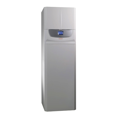
  9. Immergas VICTRIX 50 User manual

Immergas VICTRIX 50 User manual

GENERAL WARNINGS.
All Immergas products are protected with suitable transport
packaging.
e material must be stored in a dry place protected from the
weather.
This instruction manual provides technical information for
installing the Immergas kit. As for the other issues related to kit
installation (e.g. safety at the workplace, environmental protection,
accident prevention), it is necessary to comply with the provisions
specied in the regulations in force and with the principles of good
practice.
Improper installation or assembly of the Immergas appliance and/
or components, accessories, kits and devices can cause unexpected
problems for people, animals and objects. Read the instructions
provided with the product carefully to ensure proper installation.
Installation and maintenance must be performed in compliance
with the regulations in force, according to the manufacturer's in-
structions and by professionally qualied sta, meaning sta with
specic technical skills in the plant sector, as envisioned by the law.
AVVERTENZE GENERALI.
Tutti i prodotti Immergas sono protetti con idoneo imballaggio
da trasporto.
Il materiale deve essere immagazzinato in ambienti asciutti ed al
riparo dalle intemperie.
Il presente foglio istruzioni contiene informazioni tecniche relative
all’installazione del kit Immergas. Per quanto concerne le altre
tematiche correlate all’installazione del kit stesso (a titolo esempli-
cativo: sicurezza sui luoghi di lavoro, salvaguardia dell’ambiente,
prevenzioni degli infortuni), è necessario rispettare i dettami della
normativa vigente ed i principi della buona tecnica.
L’installazione o il montaggio improprio dell’apparecchio e/o dei
componenti, accessori, kit e dispositivi Immergas potrebbe dare
luogo a problematiche non prevedibili a priori nei confronti di
persone, animali, cose. Leggere attentamente le istruzioni a corredo
del prodotto per una corretta installazione dello stesso.
L'installazione e la manutenzione devono essere eettuate in
ottemperanza alle normative vigenti, secondo le istruzioni del co-
struttore e da parte di personale abilitato nonché professionalmente
qualicato, intendendo per tale quello avente specica competenza
tecnica nel settore degli impianti, come previsto dalla Legge.
KIT VALVOLA TRE VIE PER ABBINAMENTO
UNITÀ BOLLITORE VICTRIX 50-75-90-115
COD. 3.015223
IT IE
VICTRIX 50-75-90-115 3-WAY VALVE KIT
FOR COUPLING WITH GENERATOR UNIT
CODE 3.015223
Code 1.020128 - Rev. ST.006579/001
STD.009321/001
Montaggio Kit.
Premontare il gruppo tre vie in ottone (4) con il motorino (5), in modo che il
lato morsettiera dello stesso sia posizionato verso il lato "A" stampato sul corpo
tre vie in ottone (4), accessibile comunque dalla parte anteriore della caldaia.
Montare il tubo (6) alla valvola miscelatrice (lato A) interponendo la relativa
guarnizione senza serrare a fondo il dado.
Montare la valvola (4) con tubo (6) al collettore (3) interponendo le relative
guarnizioni senza serrare a fondo i dadi.
Al termine serrare a fondo tutti i dadi di collegamento.
Collegare il kit 3 vie per abbinamento unità bollitore come da gura 2 assicu-
randosi di interporre le guarnizioni (1).
Legenda:
1 - Guarnizione
2 - Tronchetto di mandata all'unità bollitore
3 - Collettore 3 vie
4 - Valvola 3 vie in ottone
5 - Motore azionamento valvola
6 - Tubo di raccordo
G1" 4
1
5
6
G1"1/2
G1"1/2
1
G1"1/2
G1"
2
A
B
AB
G1"
G1"
G1"
3
Key:
1 - Seal
2 - Delivery section to generator unit
3 - 3-way valve mainfold
4 - Brass 3-way valve
5 - Valve operation motor
6 - Connection pipe
Kit assembly.
Preassemble the brass 3-way unit (4) with motor (5), so that its terminal block
side is positioned towards side “A” stamped on brass 3-way body (4), and in
any case accessible from the front of the boiler.
Fit pipe (6) on the mixer valve (side A), interposing the relevant seal without
tightening down the nut.
Fit the valve (4) with pipe (6) on mainfold (3), interposing the relative seals
without tightening down the nuts.
On completion, tighten down all the connection nuts.
Connect the 3-way kit for coupling with generator unit as shown in g. 2, making
sure to interpose the seals (1).
Fig. 1
Fig. 2
STD.009321/001
Sonda boiler
Boiler sensor
Valvola tre vie
3-way valve
Allacciamento elettrico.
N:B: nel caso di utilizzo dell’unità bollitore Immergas, è necessario sostituire
la sonda boiler già montata sull’unità bollitore con la sonda boiler presente
all’interno del kit valvola 3 vie.
Collegare la sonda boiler (B2) presente nel kit sui morsetti R e H della mor-
settiera assicurandosi di aver precedentemente asportato il ponticello (R8).
Collegare i cavi provenienti dal motore comando valvola a tre vie (M30) come
descritto nella gura sotto riportata.
Collegare il connettore (3) al morsetto (T) utilizzando il cavo nero fornito
in dotazione.
Collegare il connettore (6) al morsetto (S) utilizzando il cavo arancio fornito
in dotazione.
Collegare il connettore (2) al morsetto (K) utilizzando il cavo rosso fornito
in dotazione.
Attenzione: La caldaia ha un grado di isolamento elettrico IPX5D e può essere
installata anche all'esterno senza bisogno di protezioni aggiuntive, è opportuno
comunque se installati all'esterno coibentare le tubazioni e proteggere dagli
agenti atmosferici il kit in base al suo grado di protezione elettrica.
MANDATA
BOILER
RITORNO
BOILER
BOILER
DELIVERY
BOILER
RETURN
Electrical connection.
N.B.: if the Immergas generator unit is used, the boiler sensor already tted
on the generator unit must be replaced with boiler sensor included in the
3-way valve kit.
Connect boiler sensor (B2), included in the kit, to terminals R and H on the
terminal board, making sure to previously remove the jumper (R8).
Connect the cables coming from the 3-way valve control motor (M30) as
described in the gure below.
Connect connector (3) to terminal (T) using the black cable supplied.
Connect connector (6) to terminal (S) using the orange cable supplied.
Connect connector (2) to terminal (K) using the red cable supplied.
Important: e boiler has IPX5D electrical insulation rating and can also
be installed outside, without requiring additional protection; however, if
installed outside it is advisable to insulate the piping and protect the kit from
atmospheric agents according to its electrical protection rating.
Fig. 3
Fig. 4
STD.009321/001
Parametri modicabili.
Parame-
tro descrizione Valore limite
inferiore
Valore limite
superiore
Valore di
fabbrica
1
Valore di set
acqua calda
sanitaria
20 °C 70 °C 20 °C
2
Modalità di
funzionamento
sanitario
0 = escluso
1 = attivo
2 = escluso + pompa continua
3 = attivo + pompa continua
0
3
Modalità di
funzionamento
riscaldamento
0 = escluso
1 = attivo
2 = escluso + pompa continua
3 = attivo + pompa continua
1
4
Temperatura
massima di
mandata riscal-
damento
20 °C 90 °C 85 °C
La caldaia esce di fabbrica impostata come solo riscaldamento, nel caso in cui
si installi un unità bollitore esterno occorre modicare le impostazioni della
scheda di caldaia nel seguente modo:
- premere il tasto MODE una volta per accedere alla modalità parametri
(PARA)
- per mezzo del tasto STEP scegliere il parametro da modicare (parametro
1)
- cambiare il valore agendo sui tasti + o -
- premere il tasto STORE per memorizzare il nuovo valore
- per mezzo del tasto STEP scegliere il parametro da modicare (parametro
2)
- cambiare il valore agendo sui tasti + o - (impostandolo su 1)
- premere il tasto STORE per memorizzare il nuovo valore
Per eventuali regolazione della potenza in sanitario vedere indicazioni sul
libretto di caldaia.
Modiable parameters.
Param-
eter description Lower limit
value
Upper limit
value
Factory
value
1
Domestic hot
water setting
value
20 °C 70 °C 20 °C
2
Domestic hot
water function
mode
0 = cut out
1 = active
2 = cut out + continuous pump
3 = active + continuous pump
0
3Heating func-
tion mode
0 = cut out
1 = active
2 = cut out + continuous pump
3 = active + continuous pump
1
4
Max. heating
delivery tem-
perature 20 °C 90 °C 85 °C
Boilers leave the factory set for heating only; to install an external generator
unit the boiler card settings must be modied as follows:
- press the MODE key once to enter parameter mode (PARA)
- using the STEP key select the parameter to be changed (parameter 1)
- use the + or - keys to change the value
- press the STORE key to store the new value
- using the STEP key select the parameter to be changed (parameter 2)
- use the + or - keys to change the value (setting it to 1)
- press the STORE key to store the new value
For any adjustment of output in domestic hot water see instructions in the
boiler manual.
STD.009321/001

Other manuals for VICTRIX 50

5

This manual suits for next models

4

Other Immergas Boiler manuals

Immergas ZEUS Mini User manual

Immergas

Immergas ZEUS Mini User manual

Immergas UB INOX 80 ErP Operating instructions

Immergas

Immergas UB INOX 80 ErP Operating instructions

Immergas NIKE Mini Export User manual

Immergas

Immergas NIKE Mini Export User manual

Immergas HERCULES Solar 26 1 A User manual

Immergas

Immergas HERCULES Solar 26 1 A User manual

Immergas Mini Eolo 24 3 E Product manual

Immergas

Immergas Mini Eolo 24 3 E Product manual

Immergas VICTRIX EXA 24 X 1 ErP Operating instructions

Immergas

Immergas VICTRIX EXA 24 X 1 ErP Operating instructions

Immergas VICTRIX 90 1I User manual

Immergas

Immergas VICTRIX 90 1I User manual

Immergas VICTRIX 24 TT 1E Product manual

Immergas

Immergas VICTRIX 24 TT 1E Product manual

Immergas VICTRIX OMNIA Operating instructions

Immergas

Immergas VICTRIX OMNIA Operating instructions

Immergas Victrix Zeus 25 Operating instructions

Immergas

Immergas Victrix Zeus 25 Operating instructions

Immergas Victrix Tera 28 1 User manual

Immergas

Immergas Victrix Tera 28 1 User manual

Immergas VICTRIX EXA 24x1 ERP Operating instructions

Immergas

Immergas VICTRIX EXA 24x1 ERP Operating instructions

Immergas VICTRIX X 12-24 2 I User manual

Immergas

Immergas VICTRIX X 12-24 2 I User manual

Immergas ARES 150 TEC ERP User manual

Immergas

Immergas ARES 150 TEC ERP User manual

Immergas Hercules Condensing 26 2 E User manual

Immergas

Immergas Hercules Condensing 26 2 E User manual

Immergas VICTRIX 75 User manual

Immergas

Immergas VICTRIX 75 User manual

Immergas VICTRIX EXA 28 1 ERP Operating instructions

Immergas

Immergas VICTRIX EXA 28 1 ERP Operating instructions

Immergas Maior Eolo 24 4E Product manual

Immergas

Immergas Maior Eolo 24 4E Product manual

Immergas ZEUS 24 Superior User manual

Immergas

Immergas ZEUS 24 Superior User manual
Immergas NIKE ECO 24 User guide

Immergas

Immergas NIKE ECO 24 User guide

Immergas MAGIS HERCULES PRO User manual

Immergas

Immergas MAGIS HERCULES PRO User manual

Immergas MINI EOLO 24 3E Product manual

Immergas

Immergas MINI EOLO 24 3E Product manual

Immergas ZEUS 24 kW User manual

Immergas

Immergas ZEUS 24 kW User manual

Immergas VICTRIX 20 Plus User manual

Immergas

Immergas VICTRIX 20 Plus User manual

Popular Boiler manuals by other brands

Smith 70-195 Installation and operation instructions

Smith

Smith 70-195 Installation and operation instructions

Truma BOA operating instructions

Truma

Truma BOA operating instructions

IDEAL SUPER PLUS 200/S Installation and servicing

IDEAL

IDEAL SUPER PLUS 200/S Installation and servicing

Potterton Titanium 24 Installation & service instructions

Potterton

Potterton Titanium 24 Installation & service instructions

Hydro-Smart 170 Installation manual and owner's guide

Hydro-Smart

Hydro-Smart 170 Installation manual and owner's guide

Vaillant ecoTEC pro 28 Instructions for installation and servicing

Vaillant

Vaillant ecoTEC pro 28 Instructions for installation and servicing

Alpha InTec2 26CE Installation and servicing instructions

Alpha

Alpha InTec2 26CE Installation and servicing instructions

Alpha DS 24 TF Instruction and warning book

Alpha

Alpha DS 24 TF Instruction and warning book

Olsen OQ95M-200 installation manual

Olsen

Olsen OQ95M-200 installation manual

Keston Qudos 37 User's installation guide

Keston

Keston Qudos 37 User's installation guide

Unical KONm R 18 Installation and Servicing Manual

Unical

Unical KONm R 18 Installation and Servicing Manual

Unical ALKON 35S C Installation and Servicing Manual

Unical

Unical ALKON 35S C Installation and Servicing Manual

Potterton Powermax HE 85 Litre Installation and servicing instructions

Potterton

Potterton Powermax HE 85 Litre Installation and servicing instructions

Baxi Solo 3 Installation and servicing instructions

Baxi

Baxi Solo 3 Installation and servicing instructions

Bosch Worcester GREENSTAR CDi CLASSIC REGULAR ErP... Installation, commissioning and servicing instructions

Bosch

Bosch Worcester GREENSTAR CDi CLASSIC REGULAR ErP... Installation, commissioning and servicing instructions

Hoval CombiVal Assembly instructions

Hoval

Hoval CombiVal Assembly instructions

Viessmann B2HA 19 installation instructions

Viessmann

Viessmann B2HA 19 installation instructions

ACV E-Tech W 09 Installation, operating and servicing instructions

ACV

ACV E-Tech W 09 Installation, operating and servicing instructions

manuals.online logo
manuals.online logoBrands
  • About & Mission
  • Contact us
  • Privacy Policy
  • Terms and Conditions

Copyright 2025 Manuals.Online. All Rights Reserved.