Immergas Trio Base V2 Product manual

TRIO V2
TRIO MONO V2
Base
Combi
Plus
Pro
IE
Instructions and warnings
Installer
User
Maintenance technician
*1.042679ENG*
*1.042679ENG*


Dear Customer,
Congratulations for having chosen a top-quality Immergas product, able to assure well-being and safety for a long period of time. As an Immergas Customer,
you can also count on a qualied aer-sales service, prepared and updated to guarantee constant eciency of your product. Read the following pages carefully:
you will be able to draw useful tips on the proper use of the device, compliance with which will conrm your satisfaction with the Immergas product.
For assistance and routine maintenance, contact Authorised Service Centres: they have original spare parts and are specically trained directly by the manufacturer.
General warnings
All Immergas products are protected with suitable transport packaging.
e material must be stored in a dry place protected from the weather.
e instruction booklet is an integral and essential part of the product and must be given to the new user in the case of transfer or succession of ownership.
It must be stored with care and consulted carefully, as all of the warnings provide important safety indications for installation, use and maintenance stages.
is instruction manual provides technical information for installing the Immergas pack. As for the other issues related to pack installation (e.g. safety in the
work site, environment protection, injury prevention), it is necessary to comply with the provisions specied in the regulations in force and good practice rules.
In compliance with legislation in force, the systems must be designed by qualied professionals, within the dimensional limits established by the Law. Installation
and maintenance must be performed in compliance with the regulations in force, according to the manufacturer's instructions and by professionally qualied
sta, intended as sta with specic technical skills in the system sector, as envisioned by the Law.
Improper installation or assembly of the Immergas appliance and/or components, accessories, kits and devices can cause unexpected problems for people,
animals and objects. Read the instructions provided with the product carefully to ensure proper installation.
Maintenance must be carried out by skilled technical sta. e Authorised Aer-sales Service represents a guarantee of qualications and professionalism.
e appliance must only be destined for the use for which it has been expressly declared. Any other use will be considered improper and therefore potentially
dangerous.
If errors occur during installation, operation and maintenance, due to non-compliance with technical laws in force, standards or instructions contained in
this book (or however supplied by the manufacturer), the manufacturer is excluded from any contractual and extra-contractual liability for any damage and
the appliance warranty is invalidated.
e company IMMERGAS S.p.A., with registered oce in via Cisa Ligure 95 42041 Brescello (RE), declares that the design, manufacturing and aer-sales
assistance processes comply with the requirements of standard UNI EN ISO 9001:2015.
For further details on the product CE marking, request a copy of the Declaration of Conformity from the manufacturer, specifying the appliance model
and the language of the country.
e Trio V2 system consists of separate units, some of which are excluded from this supply to allow the correct combination of features. Below are the
possible combinations through which the system is able to meet the winter central heating / C.H., summer cooling requirements, as well as the production
of domestic hot water.
Trio Base V2
Trio Base Mono V2
Trio Combi V2
Trio Combi Mono V2
Trio Plus V2
Trio Plus Mono V2
Trio Pro V2
Trio Pro Mono V2
Standard
supply
Hydronic group
1 or 2 zones
Hydronic group
1 or 2 zones
Hydronic group
1 or 2 zones
Hydronic group
1 or 2 zones
160 litre storage tank unit 160 litre storage tank unit 160 litre storage tank unit 160 litre storage tank unit
Electronics with management
board
Electronics with management
board
Electronics with management
board
Electronics with management
board
Excluded
from this
supply
Hydronic module kit
for Audax Top ErP
Audax Top ErP coupling kit for
instantaneous boilers
Audax Top ErP coupling kit for
Plus boilers Magis Pro coupling kit
Solar Container or Domus
Container
Solar Container or Domus
Container
Solar Container or Domus
Container
Solar Container or Domus
Container
Audax 6 - 8 - 12 Audax 6 - 8 - 12 Audax 6 - 8 - 12 Magis Pro 5 - 8 - 10 ErP
-
Boilers which can be coupled:
Victrix 28 - 35 kW TT
Victrix Tera 24 - 28
Victrix Omnia
Boilers which can be coupled:
Victrix 12 - 24 - 32 kW TT Plus
Victrix Tera 24 Plus
-
System resistance kit
DHW (Domestic hot water) 1.5
kW resistance kit
Solar heating coupling kit
Inertial storage tank kit
Solar heating coupling kit
Inertial storage tank kit
Solar heating coupling kit
Inertial storage tank kit
DHW (Domestic hot water) 1.5
kW resistance kit
System 3.0 kW resistance kit
Solar heating coupling kit
Inertial storage tank kit
e manufacturer declines all liability due to printing or transcription errors, reserving the right to make any modications to its technical and commercial
documents without forewarning.

INDICE
USER pageINSTALLER page MAINTENANCE TECHNICIAN page
1 Installation Trio V2 ....................................5
1.1 Description of the device...........................5
1.2 Installation recommendations..................5
1.3 Packaging..................................................... 5
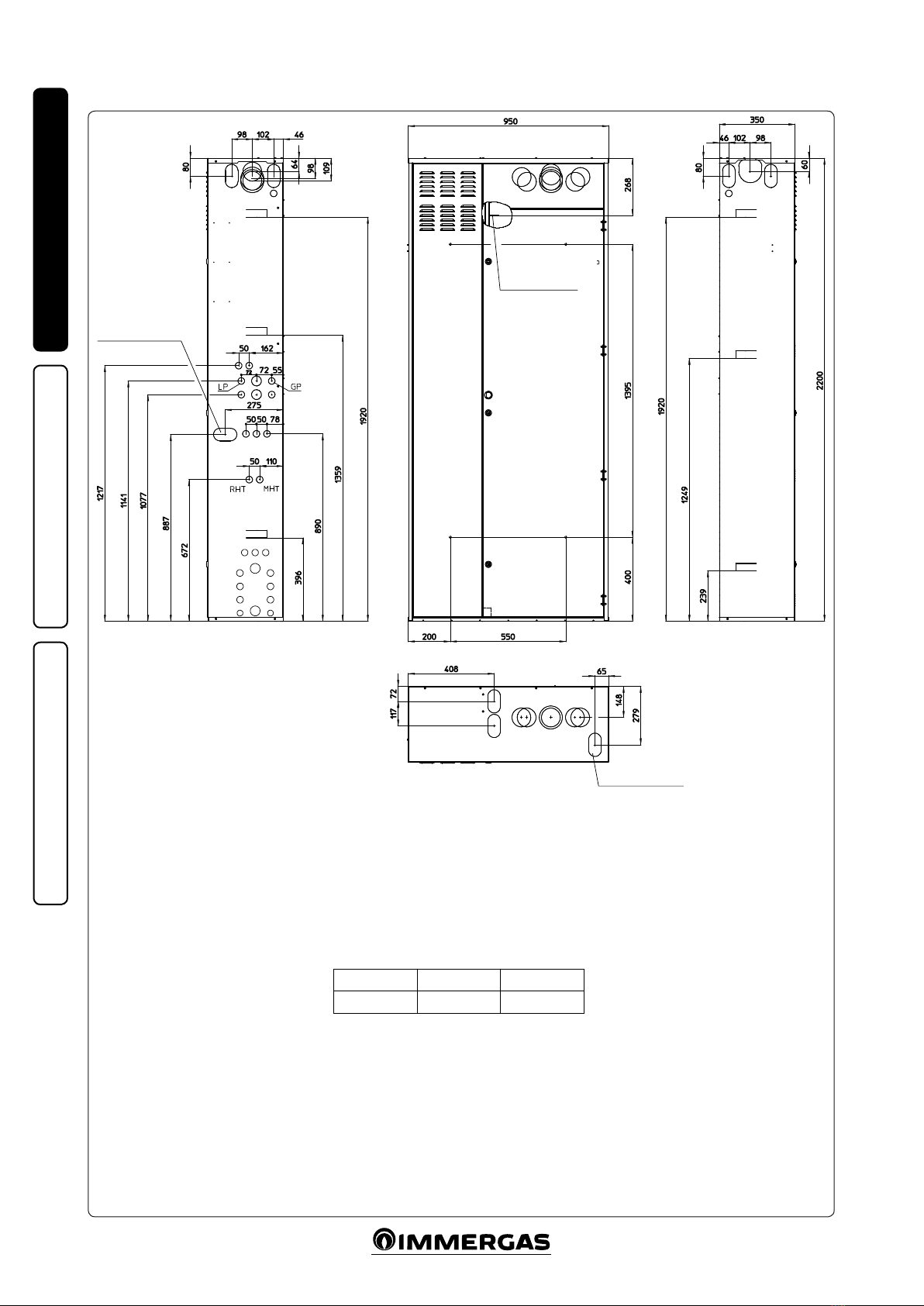
1.4 Overall dimensions.....................................6
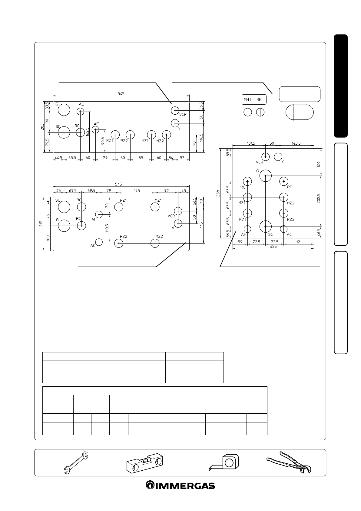
1.5 Connection template..................................7
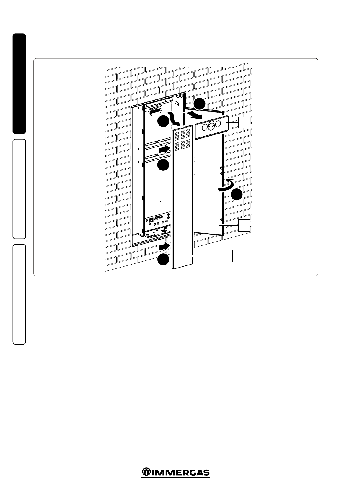
1.6 Installation...................................................9
1.7 Trio V2 (Base) wiring connection
diagram. .....................................................25
1.8 Remote panel main dimensions .............26
1.9 Remote panel installation operations.....26
1.10Gas connection (where the optional
boiler is present). ......................................27
1.11Hydraulic connection...............................27
1.12Safety valve drain......................................27
1.13Condensate drain (where the optional
boiler is present). ......................................27
1.14Electrical connection................................27
1.15Room thermostats (Optional). ...............30
1.16Audax control panel. ................................30
1.17 Secondary zone remote control (optional)....30
1.18 Solar control unit installation (Optional).......31
1.19Antifreeze protection. ..............................33
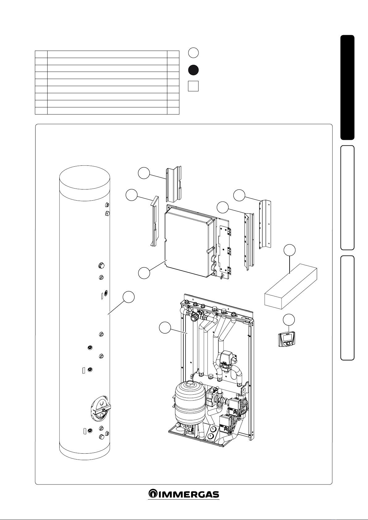
1.20Trio Base V2 main components..............34
1.21Main components Trio Base V2 with
integrated resistances (Optional)............35
1.22Main components Trio Combi V2 with
instantaneous boiler (Optional) .............36
1.23Main components Trio Combi V2 with
Victrix Omnia (Optional) .......................37
1.24Main components Trio Plus V2 with
Plus boiler (Optional) ..............................38
1.25Main components Trio Pro V2 with
Magis Pro (Optional)...............................39
1.26Main components solar heating system
coupling kit (Optional)............................40
1.27Trio Base V2 hydraulic diagram.............41
1.28Hydraulic diagram Trio Base V2 with
integrated resistances (Optional)............42
1.29Hydraulic diagram Trio Combi V2 with
instantaneous boiler (Optional) .............43
1.30Hydraulic diagram Trio Combi V2 with
Victrix Omnia (Optional) .......................44
1.31Hydraulic diagram Trio Combi Mono V2
with instantaneous boiler (Optional).....45
1.32Hydraulic diagram Trio Combi Mono V2
with Victrix Omnia (Optional)...............46
1.33Hydraulic diagram Trio Plus V2 with
Plus boiler (Optional). .............................47
1.34Hydraulic diagram Trio Pro V2 with
Magis Pro (Optional)...............................48
1.35Hydraulic diagram solar heating system
coupling kit (Optional)............................49
1.36Hydraulic diagram V2 DHW
(Domestic hot water) three-way priority
valve (Optional)........................................50
1.37Mixing valve. .............................................51
1.38Commissioning (Ignition).......................51
1.39Boiler commissioning (if present)..........51
1.40Gas system commissioning (where the
optional boiler is present)........................51
1.41Commissioning solar heating system
coupling kit (Optional)............................51
1.42Cooling / Central heating circuit / C.H.
circuit system lling. ................................51
1.43 Filling the solar circuit system (Optional)...52
1.44Sizing the systems.....................................52
1.45Kits available on request. .........................53
1.46Circulation pump (Trio)..........................53
1.47Circulation pump (solar thermal system
coupling kit). .............................................55
2 Instructions for use and maintenance....57
2.1 Cleaning and maintenance......................57
2.2 General warnings......................................57
2.3 Decommissioning.....................................57
2.4 Trio remote panel (main). .......................58
2.5 System use..................................................58
2.6 Comfort / Economy / Manual Operation. ....59
2.7 Operation with external probe................59
2.8 Clock and programs.................................59
2.9 Settings menu............................................60
2.10 DHW (Domestic hot water) set setting.... 63
2.11Fault and anomaly signals. ......................64
2.12 Use of the remote zone control (optional).....66
2.13Using the secondary zone Remote panel
(optional). ..................................................67
2.14Fault and anomaly signals. ......................69
3 Control and maintenance........................70
3.1 Trio V2 wiring diagram...........................71
3.2 Trio Mono V2 wiring diagram................72
3.3 System programming...............................73
3.4 Programming and use of the zone
remote panel..............................................79
3.5 External temperature probe (Optional).... 80
3.6 Programming the remote zone control
parameters (Optional). ............................80
3.7 Photovoltaic function...............................81
3.8 Deaeration Function. ...............................81
3.9 Victrix kW TT Special functions............81
3.10Victrix Tera Special functions.................81
3.11Magis Pro Special functions....................81
3.12Radiant panel systems..............................81
3.13Flow set calculation..................................81
3.14Annual maintenance:...............................82
3.15Decommissioning.....................................82
3.16Technical data. ..........................................83
3.17Product sheet.............................................83
3.18Product che (in compliance with
Regulation 812/2013)...............................84

5
1
INSTALLERUSER
MAINTENANCE TECHNICIAN
1 INSTALLATION
TRIO V2
1.1 DESCRIPTION OF THE DEVICE.
e Trio V2 pack described below allows you to
install in a special recessed frame called “Solar
Container” (not included in the supply) a hy-
dronic unit designed to be coupled with dierent
energy sources (heat pump, boiler, solar, excluded
from this supply), able to meet the winter central
heating / C.H., summer cooling needs, as well as
the production of domestic hot water, possibly
with solar integration (via special optional kit).
1.2 INSTALLATION
RECOMMENDATIONS.
e Trio pack has been designed solely for wall
installation using the special “Solar Container”
(recessed frame).
e place of installation of the appliance and
relative Immergas accessories must have suitable
features (technical and structural), such as to al-
low for (always in safe, ecient and comfortable
conditions):
- installation (according to the provisions of
technical legislation and technical regulations);
- maintenance operations (including scheduled,
periodic, routine and special maintenance);
- removal (outdoors in the place for loading and
transporting the appliances and components)
as well as their eventual replacement with
appliances and/or equivalent components.
Only a professionally qualied heating/plumbing
technician is authorised to install the Trio V2.
Installation must be carried out according to
regulation standards, current legislation and
in compliance with local technical regulations
and the required technical procedures. Before
installing the pack, ensure that it is delivered
in perfect condition; if in doubt, contact the
supplier immediately. Packing materials (sta-
ples, nails, plastic bags, polystyrene foam, etc.)
constitute a hazard and must be kept out of the
reach of children. Keep all ammable objects
away from the appliance (paper, rags, plastic,
polystyrene, etc.). In the event of malfunctions,
faults or incorrect operation, turn the device o
immediately and contact an authorised company
(e.g. the Authorised Technical Assistance Centre,
which has specically trained sta and original
spare parts). Do not attempt to modify or repair
the appliance alone. Failure to comply with the
above implies personal responsibility and inval-
idates the warranty.
• Installation Standards: this pack must be in-
stalled inside an external wall using the special
“Solar Container” and securing it with the
support brackets supplied together with the
pack itself. It was not designed to be installed
on plinths or oors and without the special
recessed frame.
Attention: installation of the “Solar Container” in
the wall must ensure a stable and ecient support
of the Trio V2 pack. e “Trio V2” ensures appro-
priate support only if installed correctly (accord-
ing to the rules of good practice), following the
instructions on its instructions leaet. e “Solar
Container” for the Trio V2 pack is not a support-
ing structure and must not replace the removed
wall; it is therefore verify its position in the wall.
For safety reasons against any leaks it is necessary
to plaster the pack housing in the brick wall.
is pack is used to heat water to below boiling
temperature in atmospheric pressure. It must
be connected to a central heating system and
domestic hot water circuit suited to its perfor-
mance and capacity.
“Anti-legionella” heat treatment of the
Immergas storage tank (activated by the spe-
cic function present on the predisposed ther-
moregulation systems): during this stage, the
temperature of the water inside the storage tank
exceeds 60°C with a relative risk of burns. Keep
this domestic hot water treatment under control
(and inform the users) to prevent unforeseeable
damage to people, animals, things.
1.3 PACKAGING.

6
2
INSTALLERUSER
MAINTENANCE TECHNICIAN
1.4 OVERALL DIMENSIONS.
Inertial storage tank
connection
ermal solar
systems circuit
connecting bracket
Height (mm) Width (mm) Depth (mm)
2200 950 350
Inertial storage tank
connection

7
3
INSTALLERUSER
MAINTENANCE TECHNICIAN
Connections
GAS
DOMESTIC
HOT WATER
/ D.H.W.
SYSTEM AUDAX TOP ERP MAGIS PRO
GAC AF RZ1 MZ1 RZ2 MZ1 MHT RHT LP GP
1/2” 1/2” 1/2” 3/4” 3/4” 3/4” 3/4” 3/4” 3/4” G 3/8”
SAE
G 5/8”
SAE
1.5 CONNECTION TEMPLATE.
Key:
G - Gas supply
AC - Domestic hot water outlet
AF - Domestic hot water inlet
MHT - Flow from heat pump
RHT - Return to heat pump
LP - Chiller line - liquid phase
GP - Chiller line - gaseous phase
MZ1 - Zone 1 system ow
MZ2 - Zone 2 system ow
RZ1 - Zone 1 system return
RZ2 - Zone 2 system return
RC - DHW (Domestic hot water) recircula-
tion (excluding Combi version)
SC - Condensate drain
V - Electrical connection
VCR - Remote control electrical connection
VS - 3 bar discharge valve
RIGHT HAND SIDE CONNECTION
REAR CONNECTION
HEAT PUMP CONNECTION
(For details of values see Fig. 2)
LOWER CONNECTION
Zone 1 Zone 2
Trio V2 Low temperature zone
(mixed zone)
High temperature zone
(direct zone)
Trio Mono V2 Not Present Direct zone
ZONE CONNECTION TABLE.
Attention: the indicated values refer to the stickers applied inside the recessed frame.
FLOW AND RETURN
FOR INERTIAL
STORAGE TANK

8
4
INSTALLERUSER
MAINTENANCE TECHNICIAN
PRESECTION DETAIL FOR FLUE CONNECTION.
Ref. A
(Front and rear ue connection)
Ref. B
(Upper ue connection)
Attention: For Victrix series TT, TT Plus and Victrix Tera and Tera Plus and for Victrix
Omnia with 60 / 100 concentric kit, it is always necessary to also use the 60 /
100 anged kit
TT and TT Plus - Victrix Tera and Tera Plus - Victrix Omnia series boilers
N.B.: not used for this version.
Height Connection
TT - TT Plus - Tera - Tera Plus
98 Discharge 80
107 Concentric
111 Intake 80

9
5
b
d
b1
b2
a
c
b1
b2
d1
INSTALLERUSER
MAINTENANCE TECHNICIAN
Installation drawings key:
Unmistakeable component identication
Sequential identication of the operation to perform
Identication of generic or not supplied component
a
1
A
1.6 INSTALLATION.
Pack composition.
Ref. Description Q.ty
a Storage tank 1
b Management electronics unit 1
b1 Support brackets for Solar Container 1
b2 Support brackets for Domus Container 1
b3 Electronics unit mount bracket with hinges 1
c Hydronic group 1 or 2 zones 1
d Accessories and screws 1
d1 Remote panel 1

10
6
1
2
3
3
4
C
A
B
INSTALLERUSER
MAINTENANCE TECHNICIAN
Installation operations.
Before installing the pack, open the “Solar
Container” completely by opening door (A) and
blocking it to prevent it from getting in the way
during the following installation procedures.
Also remove the cover (B) and the side cover (C).

11
7
5
6
d2
8
7
a
INSTALLERUSER
MAINTENANCE TECHNICIAN
• Insert and block the storage tank retaining strip
(d2) on the screws tted on the Solar Container.
• Insert the storage tank (a) into the Solar Con-
tainer with the ange positioned on the right
hand side and at the bottom, as shown in Fig.
8.

12
9
b3
9
9
d4
d5
d5
d4
99
9
9
8
d4
d4
d4
b1
b3
b1
b1
d3
d3
d3
10
d2
a
D
11
10
INSTALLERUSER
MAINTENANCE TECHNICIAN
• Fix bracket (b3) to bracket (b1) with screws
(d3) (Fig. 9).
• Tighten the brackets (b1) to the Solar Container
using screws (d4) and washers (d5) as shown
in Fig. 9.
• Bend the strip (d2) around the storage tank (a)
and fasten it with the screw (D) (Fig. 10).

13
d2
a
D
11
10
11
12
13
14
14
d6 c
d7
d7
13
INSTALLERUSER
MAINTENANCE TECHNICIAN
N.B.: in the event that the installer thinks it is
necessary, it is possible to secure the position of
the hydronic unit even further by using self-tap-
ping screws (d7), inserting them into the holes
on the lower part of the hydronic unit.
Attention: the xing screws (d6 and d7) are
present in the connection kit of the device to be
combined with the Trio V2.
• Hang the hydronic unit (c) on the central
bracket of the Solar Container. Secure the
position of the hydronic unit by fasten-
ing the screws (d6) on the central bracket
(Fig. 11).

14
12
3
3
F
F
J
H
44
4
F
F
H
2
2
2
2
21
E
F
F
F
F
13
INSTALLERUSER
MAINTENANCE TECHNICIAN
BASE Installation operations.
• Tighten the metal-sheet plate (E) with the
special screws (F).
• Position the expansion vessel (J) with manom-
eter (H) and x with the screws (F).

15
14
a
c
E
J
AC
MU
MU
RU
AF
RHT
MHT
M
M
AF
INSTALLERUSER
MAINTENANCE TECHNICIAN
• Make the hydraulic connection between the
storage tank (a), hydronic unit (c) and expan-
sion vessel (J), as shown in Fig. 14.
Perform the connections in sequence, starting
from the pipes near the rear wall up to those
near the installer, remembering to insert the
special gaskets supplied.
N.B.: before assembling the pipe with label (M),
remove the pipe that goes from the three-way
to the hydraulic manifold. Put the cap in the
kit on the manifold tting by interposing the
relative at gasket.

16
15
16
3
3
F
F
J
H
44
4
F
F
H
2
2
2
2
21
E
F
F
F
F
INSTALLERUSER
MAINTENANCE TECHNICIAN
BASE and RESISTANCE Installation oper-
ations.
• Tighten the metal-sheet plate (E) with the
special screws (F).
• Position the expansion vessel (J) with manom-
eter (H) and x with the screws (F).

17
17
5
5
5
5
L
M
M
M
M
18
a
c
L
J
AC
MU
MU
RU
AF
AF
MHT
RHT
M
INSTALLERUSER
MAINTENANCE TECHNICIAN
• Position the resistance unit (L) and secure it
with the screws (M).
• Make the hydraulic connection between the
storage tank (a), hydronic unit (c), expansion
vessel (J) and resistance (L), as shown in Fig. 18.
Perform the connections in sequence, starting
from the pipes near the rear wall up to those
near the installer, remembering to insert the
special gaskets supplied.

18
19
E
F
2
P
P2
F
1
1
E
F
2
P
P2
F
1
1
20
INSTALLERUSER
MAINTENANCE TECHNICIAN
Boiler installation operations.
• Choose the type of bracket present in the rela-
tive optional kits for your boiler model.
Victrix kW TT- Victrix Tera (Fig. 19)
Victrix Omnia (Fig. 20)
• Tighten the bracket (E) to the special upper
cross member with screws (F).
• Hang the boiler (P) on the bracket (E) installed
previously, (Fig. 19-20).

19
a
c
P
AC
RU
AF
AF
MHT
RHT
M
MU
MU
R
AC
a
c
P
AC
RU
AF
AF
MHT
RHT
M
MU
MU
RU
R
21
22
INSTALLERUSER
MAINTENANCE TECHNICIAN
Boiler hydraulic connection operations.
• Make the hydraulic connection between the
storage tank (a), hydronic unit (c) and boiler
(P), as shown in Fig. 21 for the PLUS SYSTEMS
and in Fig. 22 for the COMBI SYSTEMS.
Perform the connections in sequence, starting
from the pipes near the rear wall up to those
near the installer, remembering to insert the
special gaskets supplied.
N.B.: for easy electrical connection, move the
power supply cable of the boiler from the rear
fairlead on the valve supporting plate to the
front fairlead of the same.

20
M
a
c
P
AC
RU
AF
AF
MHT
RHT
MU
MU
R
AC
23
INSTALLERUSER
MAINTENANCE TECHNICIAN
Victrix Omnia hydraulic connection oper-
ations.
• Make the hydraulic connection between the
storage tank (a), hydronic unit (c) and Victrix
Omnia (P), as shown in Fig. 23 for the COMBI
SYSTEMS.
Perform the connections in sequence, starting
from the pipes near the rear wall up to those
near the installer, remembering to insert the
special gaskets supplied.
N.B.: for easy electrical connection, move the
power supply cable of the boiler from the rear
fairlead on the valve supporting plate to the
front fairlead of the same.
Other manuals for Trio Base V2
2
This manual suits for next models
9
Table of contents
Other Immergas Heating System manuals
Popular Heating System manuals by other brands

Frost Italy
Frost Italy SIAL slim Operation manual

Valeo
Valeo THERMO DC 200 Installation and operation instructions

Swegon
Swegon bluMartin freeAir 100 manual

Suburban
Suburban SF-20 User's information manual

Chattanooga Group
Chattanooga Group Hydrocollator SS-2 operating manual

Julabo
Julabo F38-ME operating manual