Congratulations on your new Impey product!
By following the installation guidelines below you are guaranteed a high-performing result and many years of troublefree use.
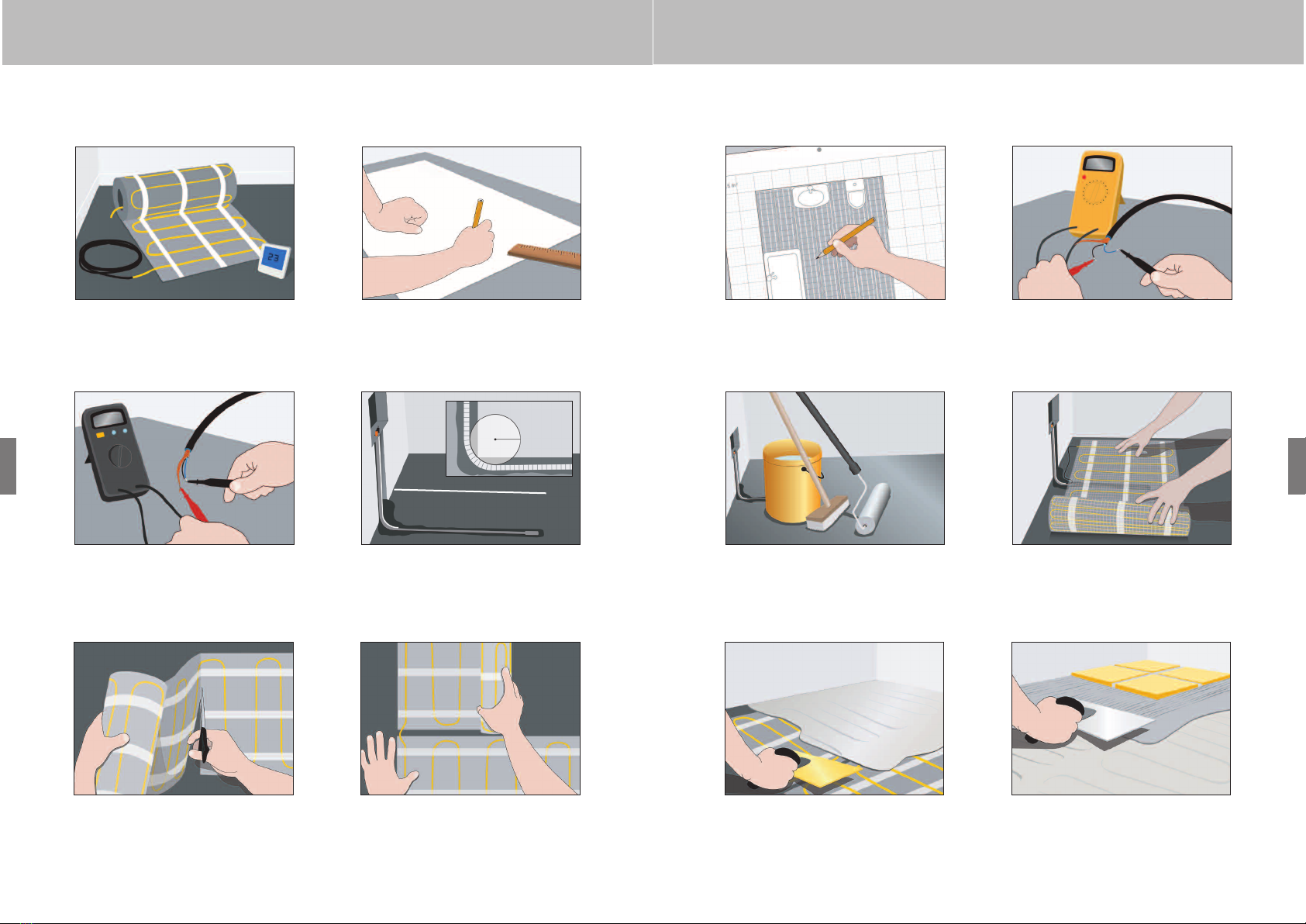
1Let’s get started
A. Necessary tools: Hammer, chisel, pencil, tape measure, craft knife, multimeter, insulation tester and this guidance leaflet
and plan.
B. Plan: Draw your room on the graph paper (fig. 2). Remember to draw in any fixed furniture/cupboards etc. and the
location of your thermostat/power supply. The heating mat should not be installed beneath items fixed to the floor, such
as cupboards, bathtubs, toilets etc.
Your Impey Aqua-Mat should have a smaller m2measurement than the available floor area. Any “excess” floor area (with
out floor heating) is spread along the walls. Draw in your Impey Aqua-Mat (w: 48 cm) with a gap of 2 cm between the
lines on the plan. Note that the adhesive backing mat under the heating cable can be cut by changing the direction on
the layout plan (fig. 3).
C. Transfer your plan with its markings onto the floor, so that you know exactly where you will start and finish.
2Test your Impey Aqua-Mat
Before you lay the heating mat you must check that the heating conductors works properly.
The resistance value is measured using a multimeter between the blue and black sections (fig. 4a). Check that the value
measured matches the value of the label attached to the cold tail connection. The value displayed must lie within -5% -
+10% of the given ohm value.
Make a note of the value measured on the proof of warranty.
Then measure the insulation value with an insulation tester by measuring between the screen (outer connector wiring) and
both the black and blue sections (fig. 4b). The measured value must be over 10 MΩ.If this is the case tick the field on the
proof of warranty.
3Preparation and cleaning
Power supply and floor sensor
Start by cutting/drilling a groove in the wall and floor from the connection point. A separate tube for the thermostat’s floor
sensor and the heating mat’s power cables is fitted into this groove (fig. 5).
Make sure that the groove for the floor sensor stretches at least 50 cm out into the room and that the sensor is placed
between two heating cables. The curve of the tube must have a radius of no less than 6 cm.
Before you fit the cable mat you must prepare the floor surface (fig. 6)
A. Make sure that loose items and sharp edges are removed and that the floor is vacuum-cleaned or washed.
B. For improved adhesion of the heating mat it is strongly recommended that the floor be primed before installation.
This must be done after the cleaning has been completed.
4Fitting
Fitting the mat
Start by removing the protective plastic foil from the mat. Start rolling it out (with the self-adhesive side towards the floor),
referring to your layout plan.
Place the start of the mat close to the electricity installation/desired thermostat location (fig. 7). Note that the connections
between the yellow heating cable and the power cables must be embedded.
Spread out the heating mat in the room, referring to your layout plan. When you meet an obstacle (walls, cupboards, toilets
or similar), cut the adhesive backing mat (not the heating cable!) and continue in a new direction (fig. 8a-8b).
If the cable, due to installation purpose, has been detached from the adhesive backing mat it can be glued to the underlay
using a glue gun.
5Midway test
After laying out the mat please measure the resistance value in the mat again (fig. 4a-4b). Use the same procedure as in
section 2 – then make a note of the values on the proof of warranty.
Installation guide
6Filling/Final measurement
When the mat has been laid as desired press the mat down against the floor to ensure optimal adhesion. Feed the 2 power
cables (blue and black) back to the thermostat connection point. Then cover the heating mat with a layer of flexible self level-
ling compound or flexible tile adhesive (fig. 9).
When subsequently laying a tiled floor on top the heating cable must simply be covered, whilst wooden floors, laminates,
rugs, vinyl etc. require a filling layer of at least 5 mm on top of the heating cable (fig. 10).
It is recommended that the self levelling compound or tile adhesive be left to harden in accordance with the manufacturer’s
instructions before the top floor is laid (tiles, wooden flooring, laminate etc.).
After fitting, measure the resistance value in the mat again (fig. 4a-4b). Use the same procedure as in section 2 – then make
anote of the values on the proof of warranty.
7Finishing
After the work has been completed the floor must harden completely before the floor heating and thermostat are connected.
This process usually takes 8-10 days, but you should refer to the filler manufacturer’s guidelines. To connect the thermostat,
please refer to the thermostat installation guidelines.
Please note that Impey Aqua-Mat must be supplied through a residual current device (RCD) having a rated residual
operating current not exceeding 30 mA.
Impey Aqua-Mat can be used with the following thermostats:
Amstat Amstat Amstat
Impey wish you all the best with your new heated floors!
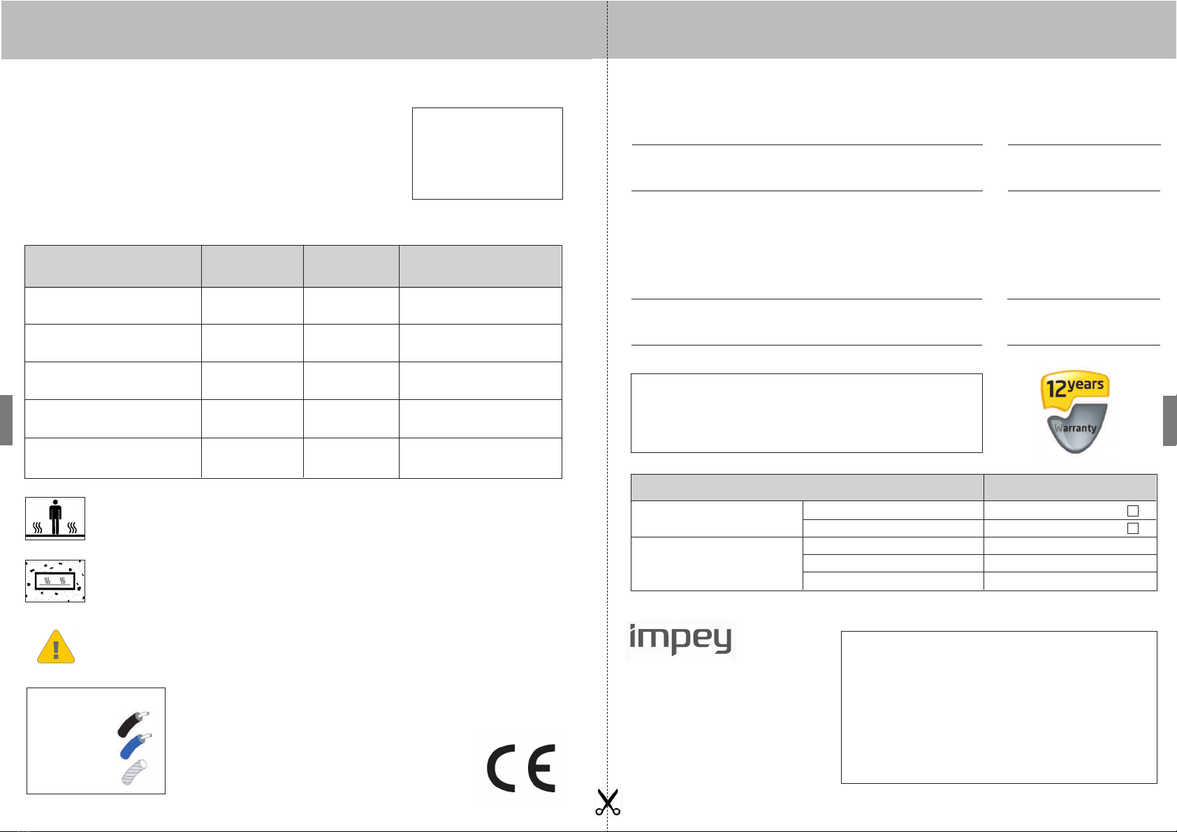
12-year warranty for Impey Aqua-Mat
Impey’sproducts have been developed for many years of trouble-free use. Assuming that they
are installed correctly – according to the installation guidelines – we therefore provide a 12-year
warranty on Impey Aqua-Mat.
The warranty covers products that appear to be defective due to manufacturing, construction or
material faults.
However,the warranty is void if:
•The product has not been installed according to the installation guidelines
•It has not been connected by an authorised electrician
•The fault is caused by inappropriate/poor floor construction
The warranty is also conditional upon the accompanying proof of warranty having been filled in correctly. The proof of war-
ranty must be retained by the owner and must be produced in the event of a claim.
In the unlikely event that you have to make use of the warranty,we will repair the product or supply a new replacement prod-
uct free of charge. The warranty does not cover any indirect or additional costs such as costs relating to the localisation of
the fault, removing the product, repairing the floor etc.
In the event of a warranty claim the product will be sent to Impey – as agreed in advance - with a tracking label attached,
stating the nature of the fault. If our investigation shows that the product is not faulty it will be returned. If we find any faults
Impey will return the repaired product or supply a new Impey product and will take away the parts that have been removed
or the faulty impey product.
No additional claims may be made against Impey under the warranty.
Installation guide