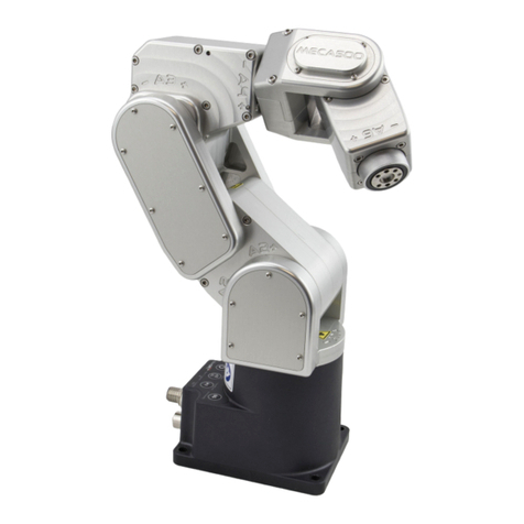
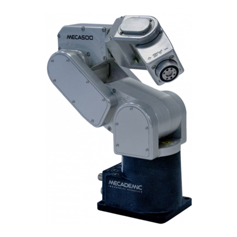
Mecademic Meca500 User manual

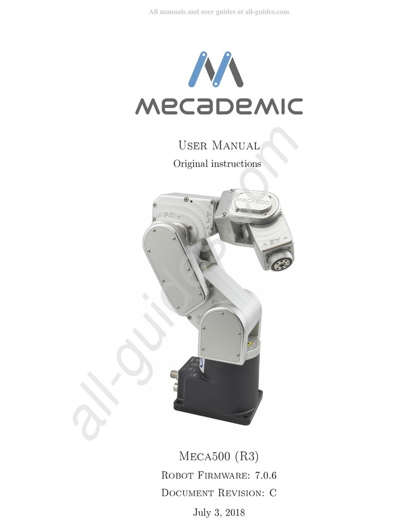
MECA500 INDUSTRIAL ROBOT (R3 & R4)
USER MANUAL
For Firmware Version 9.3.x
Document Revision: A
May 22, 2023

The information contained herein is the property of Mecademic and shall not be reproduced
in whole or in part without prior written approval of Mecademic. The information herein
is subject to change without notice and should not be construed as a commitment by
Mecademic. This manual will be periodically reviewed and revised.
While every effort has been made to ensure accuracy in this publication, no responsibility
can be accepted for errors or omissions. Data may change, as well as legislation, and you
are strongly advised to obtain copies of the most recently issued regulations, standards, and
guidelines.
This document is not intended to form the basis of a contract.
Original instructions
© Copyright 2015–2023 Mecademic

User Manual for the Meca500 Industrial Robot (for rmware 9.3.x) i
CONTENTS
1. INTRODUCTION ..............................................................................................................................................1
1.1. Inside the box................................................................................................................................................1
2. SAFETY...........................................................................................................................................................2
2.1. Power supply and safety features ................................................................................................................3
2.2. Disabling the robot brakes ...........................................................................................................................5
2.3. Limitations of the brakes..............................................................................................................................5
3. TECHNICAL SPECIFICATIONS........................................................................................................................6
4. INSTALLING THE MECA500............................................................................................................................8
5. THE MECAPORTAL .......................................................................................................................................12
5.1. Updating the robot’s firmware ...................................................................................................................12
5.2. Overview......................................................................................................................................................13
5.3. The menu bar..............................................................................................................................................14
5.3.1 The connection and robot state selectors.............................................................................................................14
5.4. The code editor panel.................................................................................................................................15
5.4.1 Using programs .....................................................................................................................................................15
5.4.2 Writing programs...................................................................................................................................................15
5.4.3 Executing programs...............................................................................................................................................17
5.5. The event log panel.....................................................................................................................................17
5.6. The 3D view panel.......................................................................................................................................18
5.6.1 The robot position display......................................................................................................................................18
5.7. The jogging panel .......................................................................................................................................19
5.7.1 The joint jog tab .....................................................................................................................................................19
5.7.2 The Cartesian jog tab............................................................................................................................................. 22
5.8. The configuration menu .............................................................................................................................24
6. OPERATING THE ROBOT ..............................................................................................................................25
6.1. Power-up procedure...................................................................................................................................25
6.1.1 Powering the robot ................................................................................................................................................25
6.1.2 Connecting to the robot .........................................................................................................................................25
6.1.3 Activating and homing the robot ...........................................................................................................................25
6.1.4 Moving the robot ....................................................................................................................................................25
6.2. Power-off procedure...................................................................................................................................27
6.2.1 Zeroing the robot joints (optional).........................................................................................................................27
6.2.2 Deactivating the robot ...........................................................................................................................................27
6.2.3 Disconnecting the robot.........................................................................................................................................27
6.2.4 Removing power ....................................................................................................................................................27
6.3. Offline mode ...............................................................................................................................................28
6.3.1 Saving the program via the web interface.............................................................................................................28
6.3.2 Running an offline program ..................................................................................................................................28
6.4. Robot control panel ....................................................................................................................................29
ii User Manual for the Meca500 Industrial Robot (for rmware 9.3.x)
6.4.1 LEDs.......................................................................................................................................................................29
6.4.2 Buttons...................................................................................................................................................................29
7. OPERATING THE INTELLIGENT POWER SUPPLY .........................................................................................31
7.1. Emergency, protective and software stops ................................................................................................31
7.2. LEDs............................................................................................................................................................32
7.3. External connections..................................................................................................................................33
8. INSTALLING AN END-EFFECTOR.................................................................................................................36
9. EXAMPLES ...................................................................................................................................................37
9.1. Draw a square.............................................................................................................................................37
10. TROUBLESHOOTING ....................................................................................................................................38
11. EC DECLARATION OF INCORPORATION.......................................................................................................39

User Manual for the Meca500 Industrial Robot (for rmware 9.3.x) iii
ABOUT THIS MANUAL
There are two manuals that come with the Meca500 industrial robot system (revision R3 or R4): this
one and the Programming Manual. This manual will guide you through the steps required for setting up
your Meca500 and for using it in a safe manner. You must read this user manual thoroughly during the
unpacking and first use of your Meca500.
Symbol definitions
The following table lists the symbols that may be used in Mecademic manuals to denote certain
conditions. Particular attention must be paid to the warning messages in this manual.
SYMBOL DEFINITION
NOTICE. Identifies information that requires special consideration.
!
CAUTION. Provides indications that must be respected in order to avoid equipment or work
(data) on the system being damaged or lost.
!
WARNING. Provides indications that must be respected in order to avoid a potentially
hazardous situation, which could result in injury.


User Manual for the Meca500 Industrial Robot (for rmware 9.3.x) 1
INTRODUCTION
1. INTRODUCTION
The Meca500 is a six-axis industrial robot arm that is easy to use, robust and lightweight. However, the
robot is a precision device with rapidly moving parts and should therefore be used only by technical
personnel who have read and understood this user manual, to avoid damages to the robot, its end-
effector, the workpiece and adjacent equipment, and, most importantly, to avoid injuries.
1.1. Inside the box
Remove all items carefully and do not discard your shipping box and packing foam.
Table 1 shows the items that come with a standard shipment of a Meca500 robot system. Your box may
also contain the MEGP 25E or MEGP 25LS electric gripper, the MPM500 pneumatic module, or other
small accessories. Do not open these additional packages immediately. You must read the grippers or
pneumatic module user manuals prior to installing the end-of-arm-tooling (EOAT) on the robot.
Table 1: Standard parts list
Qty SKU Description Photo
1 9100-001
OR
9100-002
Meca500 robot arm, revision R3
OR
Meca500 robot arm, revision R4
1 9201-001
OR
9200-003
24 V DC intelligent power supply, revision R3
OR
24 V DC intelligent power supply, revision R4
1 9403-001 D-SUB 15-position dongle
1 2003-005 Ethernet cable: 2-meter M12 D-Code to RJ45
1 2003-006 DC power cable: M12 circular male to M12 circular female DC
power cable
Note, that you must provide your own AC power cord, with three-prong IEC C13 connector on
one end, and your own country’s power plug on the other. You must also provide M6 screws of
proper length for xing the robot’s base and the power supply.
The box contains a sheet specifying the robot rmware version. If that version is not 9.3.x, go to
https://support.mecademic.com and download the corresponding user manual.

2 User Manual for the Meca500 Industrial Robot (for rmware 9.3.x)
SAFETY
2. SAFETY
The Meca500 weighs less than 5 kg, however, it can move fast and cause injuries, especially when certain
end-effectors are attached to its flange (e.g., a sharp tool or a laser). The robot also has pinch points
where robot joints can squeeze a finger (Figure1).
It is imperative that you follow the guidelines of ISO 12100:2010 and ISO 10218-2:2011 and conduct a
risk assessment of your complete robot cell, including the Meca500, its end-effector and all adjacent
equipment.
!
In the shipping position, the robot can be temporarily deposited on its base. In other robot
positions, the robot may tip and should not be placed on its base without fixing it. If the robot
tips and falls from a height, it may cause an injury, and certainly get damaged.
!
•Handle the robot with care.
•The Meca500 is equipped with brakes on its first three joints (the ones close to the base).
When the robot is not activated, these brakes are automatically applied.
Do not force the robot brakes, unless there is an emergency!
•Inspect the robot and power supply for damages. If either appears damaged, do not use
them and contact us immediately.
•Do not modify or disassemble the robot arm or the power supply.
•Do not use or store the Meca500 in a humid environment.
•Do not operate the Meca500 at temperatures below 5°C or above 45°C.
•Use only the power supply provided with your system.
•Use only the Ethernet and DC-power cables provided. Contact us if you need longer cable.
Figure1: Pinch point example

User Manual for the Meca500 Industrial Robot (for rmware 9.3.x) 3
SAFETY
2.1. Power supply and safety features
The Mecademic power supply integrates several safety features. Use only the intelligent power supply
provided by us to power your Meca500 robot arm. The Meca500 will not function with the power supply
of another revision or with a third-party 24 V DC power supply.
Power
Status
Error
RESETE-STOP
Safety I/O
Port
Robot Power
24 VDC 8.34 A
AC Power
90-264 VAC
50-60 Hz
A
B
C
D
Figure2: Power supply features
!
The latest, R4, revision of the Meca500 incorporates one major change compared to version R3:
the E-Stop no longer cuts power to the complete robot, but only to the motor drives. Do not use
the power supply of an R3 version with a Meca500 R4, and vice versa. The R4 robot arms and
power supplies are clearly indicated as being R4.
Figure2 and Figure3 show the Meca500 power supply with safety module. Its main features are:
•A: Emergency stop button (Stop Category 1), designed as PL=d with Safety Category 3.
•B: Status LEDs.
•C: Reset button.
•D: D-SUB 15-position interface (see also Figure3) for connecting safety I/O.
AC power
cable port
D-SUB
connector port
Figure3: Power supply connectors

4 User Manual for the Meca500 Industrial Robot (for rmware 9.3.x)
SAFETY
!
To start using your robot immediately, connect the D-SUB 15-position dongle to the power
supply interface, while the power supply is still switched off. NEVER CONNECT OR UNPLUG THE
DONGLE WHILE THE POWERED SUPPLY IS ON.
!
The D-SUB connector is a bypass device to be used during setup and maintenance only. You
must wire the appropriate external safety I/O connections when using the robot in production
mode (see Section 7).
!
Stand away from the robot when it is activated, wear safety goggles and be attentive and alert.
In case of an emergency, press the E-STOP button (on the power supply) immediately.
Connect the D-SUB bypass dongle to the power supply interface to get familiar with your robot. This
would deactivate the external protective stop and emergency stop connections. Read Section 7 to learn
how to wire your external safety connections.
To connect the power supply to the robot, use the DC power cable provided and never modify it.
When disconnecting the AC power, either by using the on/off switch on the power supply or by
unplugging the AC cord, the brakes on joints 1, 2 and 3 will be immediately applied and the joints will be
immobilized instantly. Therefore, to avoid premature use of the brakes, do not disconnect the AC power
when the robot is moving.
When disconnecting the AC power, pressing the E-STOP button, or activating the external E-Stop or the
protective stop(Stop Category 1), the wrist joints of the robot become free. This minimizes the risks of
pinning and pinching from the wrist and the end-effector. However, beware that the end-effector might
slowly move downwards under the effects of gravity, as shown in Figure4. Depending on the type of
end-effector used, this residual motion might lead to an injury.
!
Beware that the end-effector might slowly move downwards under the effects of gravity when
you deactivate the robot (e.g., by pressing the E-STOP button).
Figure4: When the robot is deactivated, the end-eector will slowly move downwards under the eects of gravity

User Manual for the Meca500 Industrial Robot (for rmware 9.3.x) 5
SAFETY
2.2. Disabling the robot brakes
In case of a collision, you can disable the brakes of joints 1, 2 and 3. This can only be done if the robot is
powered AND not activated. How to activate and deactivate the robot is explained later in this manual,
but for now, it suffices to say that the robot is deactivated after pressing the E-STOP button. Thus, in
case of a collision—though ideally prior to that—you must press the E-STOP button.
Then, to release the brakes of joints 1, 2 and 3, press one of the two 0G buttons on the base of the
robot continuously while holding the robot with your other hand. After 3 seconds, you will hear the
deactivation of the brakes. Continue holding the 0G button pressed and move the robot away from
obstacles. Finally, release the 0G button, and move away from the robot. Note that there is a pair of
commands to disable and re-enable the brakes. These are described in the Programming Manual.
2.3. Limitations of the brakes
Remember that the robot has brakes on joints 1, 2 and 3 only. Therefore, when the robot is deactivated
or powered off, the robot’s end-effector will go down under the effects of gravity (Figure4).
In addition, it is important to remember that the brakes used on joints 1, 2 and 3 are emergency brakes,
not locking brakes. Therefore, if you leave the robot in a configuration where the robot’s forearm is
nearly horizontal, the robot will slowly fall down under the effects of gravity, especially if you have the
maximum payload. For example, if you deactivate the robot in the configuration shown in Figure5a, the
robot's gripper might eventually collide with the table.
!
Before leaving the robot deactivated or powered off for an extended period of time, bring it to a
position that minimizes the static torques on joints 1, 2 and 3 (see Figure5).
(a) DO NOT leave the robot deactivated like this (b) DO leave it like this
Figure5: Before leaving the robot deactivated for an extended period of time, move it to a position that minimizes
the static joint torques

6 User Manual for the Meca500 Industrial Robot (for rmware 9.3.x)
TECHNICAL SPECIFICATIONS
3. TECHNICAL SPECIFICATIONS
Table 2 lists the main technical specifications of the Meca500 robot arm.
Table 2: Technical specifications for the Meca500 (R3 and R4)
TECHNICAL SPECIFICATIONS
Characteristic Value
Position repeatability 0.005 mm
Rated payload 0.5 kg
Maximum payload 1.0 kg (under special conditions)
Weight of robot arm 4.6 kg
Mounting orientations any angle
Range for joint 1 [−175°, 175°]
Range for joint 2 [−70°, 90°]
Range for joint 3 [−135°, 70°]
Range for joint 4 [−170°, 170°]
Range for joint 5 [−115°, 115°]
Range for joint 6 [−36,000°, 36,000°]
Maximum speed for joint 1 (R3|R4) 150°/s | 225°/s
Maximum speed for joint 2 (R3|R4) 150°/s | 225°/s
Maximum speed for joint 3 (R3|R4) 180°/s | 225°/s
Maximum speed for joint 4 (R3|R4) 300°/s | 350°/s
Maximum speed for joint 5 (R3|R4) 300°/s | 350°/s
Maximum speed for joint 6 (R3|R4) 500°/s | 500°/s
Maximum power consumption 200 W
Input voltage 24 VDC
Operating ambient temperature range [5°, 45°]
Operating ambient relative humidity range [10%, 80%] (non-condensing)
IP rating IP 40
Figure6 shows all the link lengths and offsets of the Meca500, necessary for obtaining the so-called
Denavit-Hartenberg parameters. Note that all joints are at zero degrees in the configuration drawn
in black line. Also note that the gray zone is the area attainable by the center of the robot’s wrist (the
intersection point of the last three axes), for a fixed angle of joint 1. This area, or even the volume
obtained by sweeping this area about the axis of joint 1 is NOT the workspace of the robot. The
workspace of the robot is a six-dimensional entity depending on the definition of the tool reference
frame. The workspace is the set of all attainable poses (positions and orientations) of the tool reference
frame with respect to the robot’s base. Even for a specific choice of a tool reference frame, it is
impossible to represent this six-dimensional workspace (read this tutorial of ours).

User Manual for the Meca500 Industrial Robot (for rmware 9.3.x) 7
TECHNICAL SPECIFICATIONS
Similarly, while the maximum tool-center point (TCP) speed is software limited to 5,000 mm/s when
the robot executes Cartesian-space motion commands, it makes no sense to specify here the actual
maximum attainable TCP speed. Indeed, the actual maximum TCP speed is highly dependent on the
robot joint position and, of course, on the TCP definition. For example, for a TCP that is located some
50mm away from the robot's flange, along the axis of joint 6, the maximum attainable TCP speed is
approximately 3500mm/s for the Meca500 R4, when the robot is fully stretched and all joints rotate at
full speed. However, in most situations, the maximum TCP speed will be much lower.
The CAD files of the Meca500 (in STEP format) can be downloaded from our web site. Alternatively,
you can use one of several robot simulation and offline programming software packages that include a
model of our Meca500, including Visual Components and RoboDK. Note that we also offer a Mecademic-
only version of RoboDK, for exclusive use with our robots.
Finally, as already mentioned, the power supply provided has an IEC C14 connector that accepts an AC
power cord with three-prong IEC C13 connector on one end, and your own country’s power plug on the
other. You can connect this power cord to any AC source that supplies voltage between 90 V and 250 V
at frequency between 50 Hz to 60 Hz.
135 135 38
120 70
R260
boundary for
wrist center
45 units: mm
Figure6: The dimensions of the Meca500 (R3 and R4)

8 User Manual for the Meca500 Industrial Robot (for rmware 9.3.x)
INSTALLING THE MECA500
4. INSTALLING THE MECA500
You are surely eager to start using your Meca500. It is, however, imperative that you fix solidly the base
of your robot arm with four M6 screws before activating the robot. We typically use metric breadboards
such as those from Thorlabs, but you can also use our adaptor plate (MUAP01), build your entire robot
cell at Vention, or use the modular system made by Tessella Automation. We recommend that you use
three kinematic positioners to constraint your base, so that you can always remove and then install it in
the exact same location. Our adaptor plate, for example, uses three locating pins.
The dimensions of the base are shown in Figure7 and an example of installation is shown in Figure8.
Note that you can install the robot base in any orientation. The robot will automatically detect the angle
between the axis of joint 1 and the gravity vector (no need to manually specify this angle). Also, note that
you can mount the robot’s base on a mobile body (e.g., on the carriage of a linear guide), but only if you
do not intend to move the robot’s joints, while the robot’s base is moving with respect to the ground.
115
4X through holes for M6
100
75
90
10
55
90
a
xis of
joint 1
45
units: mm
84
Figure7: Dimensions of the robot base
Figure8: The robot base installed, with the connectors attached

User Manual for the Meca500 Industrial Robot (for rmware 9.3.x) 9
INSTALLING THE MECA500
Do not install any end-effector yet. We will cover this topic in Section 8.
Next, you must solidly attach the power supply using four M6 screws (Figure9), at a location sufficiently
close to the robot’s base to allow connection with the 2-meter DC cable provided. However, unless you
are using an external emergency stop wired via the D-SUB connector, you must fix the power supply at
a location that makes the integrated E-STOP button readily accessible by an operator and outside the
working range of the robot.
Power
Status
Error
RESETE-STOP
Safety I/O
Port
Robot Power
24 VDC 8.34 A
AC Power
90-264 VAC
50-60 Hz
units: mm
4X through
counterbore
holes for M6
(↧6)
120
90
75
100
48
68
Figure9: Dimensions of the Meca500 intelligent power supply
The following steps must then be executed before you can start using your Meca500:
1. Attach the circular connector of the Ethernet cable to the ETHERNET1 port on the robot’s base and
connect the RJ-45 jack to your computer or router (Figure8). The two Ethernet ports on the robot’s
base act as a bridge, so you can daisy-chain several Meca500 robots, or connect an Ethernet I/O
module on the ETHERNET2 port.
2. Use the DC power cable provided to connect the unpowered power supply to the robot’s DC power
connector (Figure8). Make sure the connectors are completely screwed, or else you may damage
the robot. Then, connect the power supply to your country-specific AC power cord (not provided).
Only then, can you connect the AC power cord to an AC outlet, and switch the power supply on
using its on/off button.
3. The green LED on the power supply (next to "Power") will be illuminated. Now, you must provide
power to the robot by pressing the RESET button on the power supply. (Before you do so, make
sure the E-STOP button is disengaged by twisting it counter-clockwise.)
4. You will hear a clicking sound coming from the power supply, and the robot’s LEDs will start flash-
ing for a few seconds while the robot’s controller is booting. Once the controller ready, the red LED
on the robot’s base will start flashing intermittently.
5. Depending on which of the two Ethernet ports was used in step 1, the Link/Act IN (for ETHERNET1)
or Link/Act OUT (for ETHERNET2) green LED will stop flashing and remain illuminated, but only once
the robot has finished booting. If not, detach the Ethernet cable and repeat step 1.
6. Configure your computer Ethernet connection with a static IP address, on the same subnet as the
robot's default IP address, i.e., 192.168.0.x. The way to do this differs from one operating system to
another. Figure10 shows how to do this in Windows and in Linux.
7. Open (preferably) the latest version of Google Chrome and type Meca500’s default IP address
192.168.0.100 in the address bar.
8. Meca500’s web interface, called MecaPortal, should load instantaneously.

10 User Manual for the Meca500 Industrial Robot (for rmware 9.3.x)
INSTALLING THE MECA500
(a) Windows (b) Linux
Figure10: Two examples of how to congure the IP address of your computer
!
Always connect the DC power cable before connecting the power supply to an AC outlet. Always
disconnect the power supply from the AC outlet before disconnecting the DC power cable.
It is also possible to change the robot’s network configuration. This option is available through the
robot’s web interface, which will be described in detail in Section 5. Here is the procedure for doing so,
once you have loaded the MecaPortal but not activated your robot.
1. Click on the connection state button on the top right of the MecaPortal and select "Control" (see
Figure11).
1. Click on the configuration menu button, , in the top left corner of the MecaPortal and select "Net-
work configuration".
2. Depending on your configuration, activate the toggle DHCP to automatically receive an address
from your router or leave untoggled to force a specific IP. You don’t need to reboot the robot; the
new configuration will be applied as soon as you click on the Apply button (Figure12).
Figure11: Connection state button

User Manual for the Meca500 Industrial Robot (for rmware 9.3.x) 11
INSTALLING THE MECA500
Figure12: Changing the robot’s network conguration

12 User Manual for the Meca500 Industrial Robot (for rmware 9.3.x)
THE MECAPORTAL
5. THE MECAPORTAL
Meca500’s web interface, called MecaPortal, is more or less the equivalent of the teach pendant’s
interface of a traditional industrial robot. The interface is essentially an HTML 5 web page with JavaScript
and WebGL scripts. All of these files reside in the robot’s controller, so you do not need to install
anything on your computer, but Google Chrome.
The interface basically translates your mouse clicks, joystick movements and keyboard entries into
proprietary commands that are sent to the robot’s controller. These are primarily the same commands
described in the Programming Manual that you will eventually start sending from your own application,
written in C++, Java, Python or any other modern programming language. In addition, the web interface
displays the feedback messages received from the robot and the 3D model of the actual robot.
The MecaPortal is intended mainly for testing and writing simple programs. You must create your own
software application or program if you intend to use the robot for complex tasks, such as interacting
with inputs and outputs (in which case you also need a third-party I/O module).
The web interface is also used for updating the firmware of your robot.
The MecaPortal, introduced in firmware 9.3, is a major upgrade of the previous web interface, in terms
of aesthetics, usability and functionality. It is, however, possible to use the old web interface, but that
interface will no longer be supported. You can access the legacy web portal from the configuration menu
button, section "Help".
5.1. Updating the robot’s firmware
Before you continue to read any further, make sure that you have the latest firmware installed on the
robot and that you read the manuals corresponding to that firmware. Go to the Downloads section of
our web site and download the latest firmware (a zip file). Unzip it. Then, once you have followed the
procedures of Section 4, and before activating the WebSocket/TCP connection and activating the robot,
click on Update in the Options menu in the old web interface. A new interface will load in the same
browser tab. Click on Choose File and select the file Meca500*.update that you just extracted. Then click
on the Upload button. Wait a couple of minutes for the update to be completed. Once completed, the
robot will reboot and the new web interface will reload.
Now that you have installed the latest robot firmware, make sure to download the latest user and
programming manuals from the Downloads section of our web site and keep these manuals until you
update again your firmware.
Next time you update your robot’s firmware, you must also read the PDF file that is in the zip package
(i.e., the Release Notes). That document lists of all the recent firmware changes.
!
If you have the MEGP 25E or MEGP 25LS electric gripper or the MPM500 pneumatic module
installed on your Meca500 during the robot's firmware update, the firmware of your end-of-
arm-tooling (EOAT) will also be updated. Otherwise, you can update the firmware of your EOAT
later, by following the same procedure but selecting the m500_exttools*.update file.

User Manual for the Meca500 Industrial Robot (for rmware 9.3.x) 13
THE MECAPORTAL
5.2. Overview
Figure13 shows the main elements of the MecaPortal web interface. These are:
•The menu bar
•The code editor panel
•The jogging panel
•The 3D view panel
•The event log panel
Jogging panel Code editor panel
3D view panel
Event log panel
Menu bar
Figure13: Overview of the MecaPortal
You can show/hide each of the four panels from the button , in the menu bar.

14 User Manual for the Meca500 Industrial Robot (for rmware 9.3.x)
THE MECAPORTAL
5.3. The menu bar
From left to right, the menu bar features
•The configuration menu button,
•The panels show/hide menu button,
•The show/hide tooltips button,
•The robot name surrounded by state bars (see Table 3)
•The connection state selector, (disconnect) or (monitoring) or (control)
•The robot state selector, (deactivate) or (activate) or (home)
•The recovery mode button,
•The simulation mode button,
•The end-of-arm tooling state icon,
Until you get to know the MecaPortal, we recommend that you activate the tooltips using the
button , in the menu bar. Most tooltips are disabled by default.
Table 3: The robot state bars in the MecaPortal
ROBOT STATE BARS
Visual state Explanation
Gray, solid The robot is deactivated.
Yellow, solid The robot is activated but not homed, or is in recovery mode but not moving.
Yellow, blinking The robot is in recovery mode and executing motion commands.
Green, solid The robot is homed.
Green, blinking The robot is homed and executing motion commands.
Blue, solid The robot motion is paused.
Red, blinking The robot is in error mode.
5.3.1 The connection and robot state selectors
Normally, once the web user interface is loaded, you have not only established an HTTP connection with
the robot, but also activated the socket messaging which is the only communication channel between
the web interface and the robot. By default, the web interface connects to the robot in monitoring mode
only (as seen in Figure11). To control the robot click on the icon and select . If the robot is in error
when you connect to the robot, the connection state button will show a red blinking icon. You can
still press that button and select to only monitor or control the robot. The monitoring option can be
used to see in real-time the motion of the robot when another client (e.g., another MecaPortal, a Python
program, or a Profinet application running on a PLC) is controlling the actual robot.
Next, you need to activate and home the robot by selecting the button. A list with three options
will unroll. Click the icon to activate and home the robot. During homing, all joints rotate slightly for
approximately 4seconds. Make sure the robot is not near an obstacle.
Other manuals for Meca500
7
Table of contents
Other Mecademic Robotics manuals

Mecademic
Mecademic Meca500 (R3) Owner's manual

Mecademic
Mecademic Meca500 R3 User manual

Mecademic
Mecademic Meca500 User manual

Mecademic
Mecademic Meca500 User manual

Mecademic
Mecademic Meca500 R3 User manual

Mecademic
Mecademic MEGP 25E User manual

Mecademic
Mecademic Meca500 User manual

Mecademic
Mecademic Meca500 User manual

Mecademic
Mecademic MEGP 25E User manual

Mecademic
Mecademic Meca500 User manual