IMV EXAPad User manual

Your complete animal imaging solution
Instruction
manual

2|
Contents
1. Start Up .................................................................................................................................................................................................................................................
2. Scanner Quick Guide ..................................................................................................................................................................................................................
3. Settings .................................................................................................................................................................................................................................................
4. B Mode Imaging .............................................................................................................................................................................................................................
5. CFM Mode imaging ......................................................................................................................................................................................................................
6. PW Mode Imaging .........................................................................................................................................................................................................................
7. Power Mode imaging ..................................................................................................................................................................................................................
8. M Mode Imaging ............................................................................................................................................................................................................................
9. Freeze Mode and Cineloop .....................................................................................................................................................................................................
10. Storing of images and clips, Review ....................................................................................................................................................................................
11. Measurements .................................................................................................................................................................................................................................
12. Applications and Presets ...........................................................................................................................................................................................................
13. Patient le ...........................................................................................................................................................................................................................................
14. Protocols ..............................................................................................................................................................................................................................................
15. Report ....................................................................................................................................................................................................................................................
16. EchoPad App ....................................................................................................................................................................................................................................
17. Peripheral connectivity ...............................................................................................................................................................................................................
18. Care and maintenance ..............................................................................................................................................................................................................
19. Service Centres ...............................................................................................................................................................................................................................
3
4
5
9
11
12
13
14
16
21
25
29
31
33
34
35
37
38
39

Instruction manual
www.imv-imaging.com | 3
1. Start Up
1.1 Stand set-up
When used without the trolley, the ExaPad must be placed on a
supportive base.
In order to use the stand on the system, click on the black button as
indicated below:
The xing notches are unlocked and you can move the stand to
one of 4 positions.
1.2 Connection and disconnection of probes
To connect a probe, place the probe connector in the opening
at the back of the scanner, with the cable pointing outwards. Turn
the lock situated in the middle of the connector with slight pressure
in order to engage the locking mechanism. When the locking
mechanism is engaged, make a quarter turn clockwards so that
the probe is connected.
After connecting a probe, always place the probe in a safe place
(either on the probe holders situated on the two upper corners of
the device itself or in the probe holders on the optional trolley) in
order to avoid any damage of the probe from a shock or drop.
The probes can be changed during the examination without
restarting the device.
To disconnect a probe, make a quarter turn anti-clockwise in order
to unlock the connector. Take the connector out of the device and
store the probe, protected from shocks.
• Before disconnecting the active probe, make sure you freeze
the image.
• When starting the device, always make sure to have a probe
connected on the scanner.
• The name of the connected probe is indicated on the screen
in the top right corner.
1.3 Starting of the device
Only use the power-supply
adaptor supplied by IMV
imaging.
To start the equipment,
press the ON button located
at the back of the device
Then wait until the system
starts and displays the user
interface on the screen.
The ExaPad equipment starts in a preset mode corresponding the
connected probe. If no probe is connected, the system will display
a message “No probe”. In this case, connect a probe and click on
the probe ‘s name in the top right corner of the screen.
To turn off the scanner, long press on situated in the top left
corner of the screen, a shutdown procedure will be performed.
A forced shutdown of the device can be done by pressing the ON
switch located at the back of the scanner.
Forced shutdown should only be done when scanner is
malfunctioning.
After 3 forced shutdown in a row, a blue screen will appear.
If you are presented with the blue screen, follow the on-screen
instructions. You may be able to restart, in cases where you cannot
restart, contact your nearest service centre.
1.4 Battery
The ExaPad battery can be removed with the slider located on the
back of the scanner. When inserting the battery pack in the device,
check that it is securely connected.
When the device is plugged into mains electricity, the battery is
charging regardless of whether the scanner is on or not.
While the battery is charging, a charging indicator is displayed in
the upper right corner of the screen. There is also an indicator on
the back left of the scanner;
A green led indicates device is turned on.
A blue led indicates when the hard disk is working.
A yellow led indicates the battery is charging
A warning message will appear when the battery is lower than 10
%. Connect to a power supply or the scanner will shut down.
Starting of the device
Only use the power-supply adaptor supplied by IMV imaging.
To start the equipment, press the ON button located at the back of the device
Then wait until the system starts and displays the user interface on the screen.
The ExaPad equipment starts in a preset mode corresponding the connected probe. If no probe is
connected, the system will display a message “No probe”. In this case, connect a probe and click on
the probe ‘s name in the top right corner of the screen.
To turn off the scanner, long press on situated in the top left corner of the screen, a
shutdown procedure will be performed.
A forced shutdown of the device can be done by pressing the ON switch located at the back of the
scanner.
Forced shutdown should only be done when scanner is malfunctioning.
After 3 forced shutdown in a row, a blue screen will appear.
If you are presented with the blue screen, follow the on-screen instructions. You may be able to restart,
in cases where you cannot restart, contact your nearest service centre.
Battery
The ExaPad battery can be removed with the slider located on the back of the scanner. When inserting
the battery pack in the device, check that it is securely connected.
When the device is plugged into mains electricity, the battery is charging regardless of whether the
scanner is on or not.
While the battery is charging, a charging indicator is displayed in the upper right corner of the screen.
There is also an indicator on the back left of the scanner;
A green led indicates device is turned on.
A blue led indicates when the hard disk is working.
A yellow led indicates the battery is charging
Sorcha Stephens28/5/2019 13:34
Comm en t [2]: Drawingoftheswitch
Sorcha Stephens6/6/2019 10:16
Comm en t [3]: Justputblocksofthecolour
–thepicturedoesn’tcorrelate

4|
2. Scanner Quick Guide
2.1 Screen
The ExaPad scanner has a full touch-screen interface.
The ExaPad scanner turns on in B imaging mode with a screen
display as below:
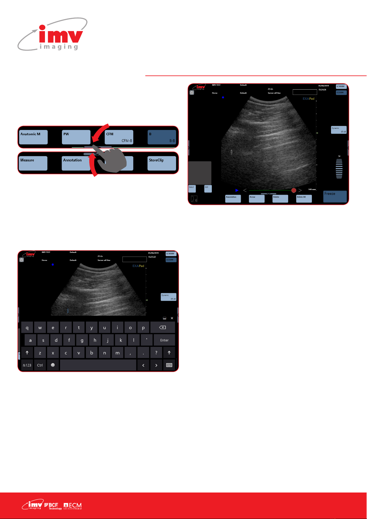
2.2 Access to the controls of the scanner
You can access the available imaging modes by clicking on the
corresponding mode: Power, M, Anatomic M, PW, CFM or Bmode.
4 modes are visible at the one time. Drag the mode menu to
access other imaging modes. The order of the modes can be
congured in the Setting page (see Settings: Page 5).
2.3 Menus
2.4 Choice of probes
ExaPad has two probe connectors located at the back of the
scanner.
The rst connector from the top of the scanner corresponds to the
probe displayed in the top of the screen.
The second connector from the top of the scanner corresponds to
the second probe displayed.
N.B: The ExaPad Mini has only one probe connector.
2. Scanner Quick Guide
Screen
The ExaPad scanner has a full touch-screen interface.
The ExaPad scanner turns on in B imaging mode with a screen display as below:
Access to the controls of the scanner
You can access the available imaging modes by clicking on the corresponding mode: Power, M,
Anatomic M, PW, CFM or B mode.
4 modes are visible at the one time. Drag the mode menu to access other imaging modes. The order of
the modes can be configured in the Setting page (Settings: Page X).
Sorcha Stephens5/6/2019 10:44
Comment [4]: Cropfromimage
Cropfromimage2
Putagraphictoshowyouswipealong?
Menus
**POINT TO M, PW, CFM, B AT BOTTOM OF SCREEN**
Each mode will activate sub-menus and specific parameters accordingly to the mode chosen.
**POINT TO DEPTH FREQUENCY FOCUS DYNAMIC AT RIGHT OF SCREEN**
Make adjustments in the sub-menu.
Choice of probes
ExaPad has two probe connectors located at the back of the scanner.
The first connector from the top of the scanner corresponds to the probe displayed in the top of the
screen.
The second connector from the top of the scanner corresponds to the second probe displayed.
**Pointtodarkbluebox**–Activeconvexprobe
**POINTTOLC1038V**-Inactivelinearprobe**
Sorcha Stephens5/6/2019 10:47
Comme n t [ 5 ] : Twoprobecrop
Make adjustments
in the sub-menu
Each mode will activate sub-
menus and specic parameters
accordingly to the mode chosen.
Active
convex probe
Inactive
linear probe
Instruction manual
www.imv-imaging.com | 5
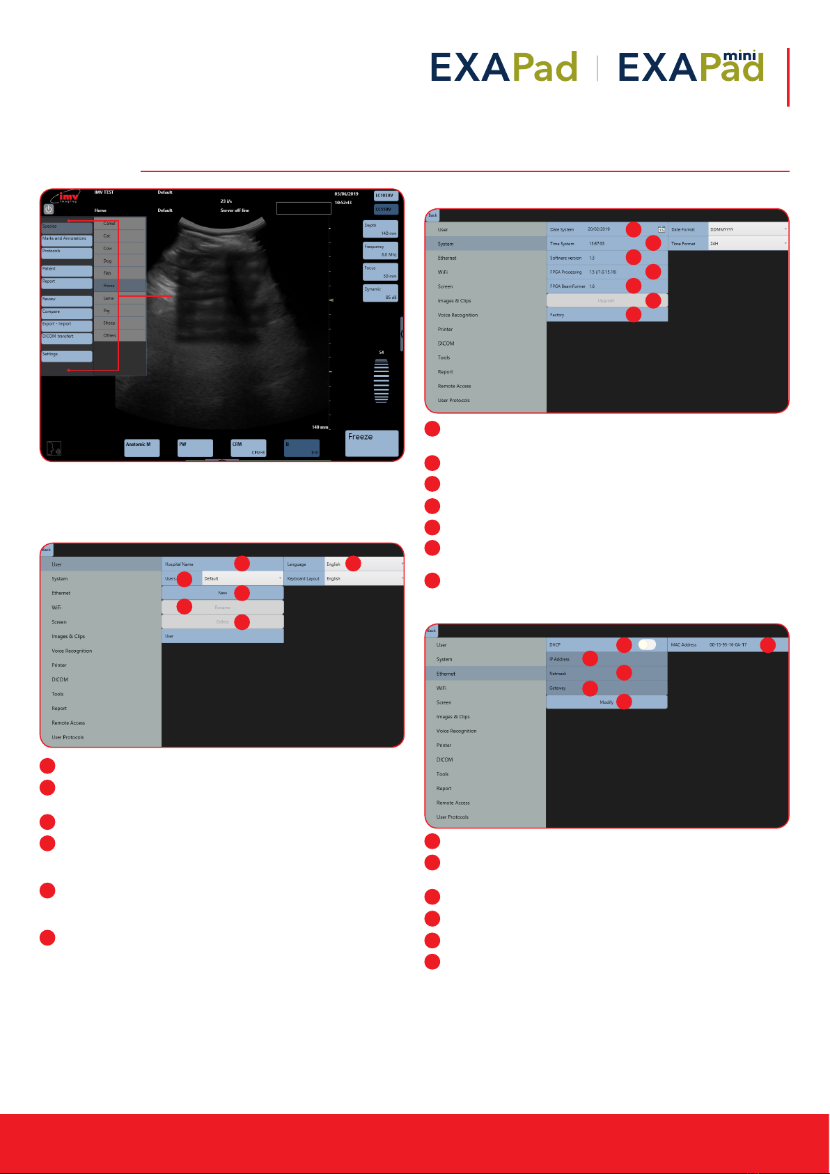
3. Settings
The Settings menu gives access to the conguration of the following
menus and sub-menus;
3.1 User Menu
Hospital name: Enter the hospital or clinic name.
Language: Choice of language for the interface and
keyboard
Users: Selection of a user name
New: Create a new user who can have individual presets. Go
to the Field User and type the users name. Conrm by clicking
Enter on the keyboard.
Rename: Select a user in the drop-down menu, click on
Rename and Conrm change by clicking Enter on the
keyboard.
Delete: Select the user in the drop-down menu, click Delete
and conrm by clicking OK in the pop-up window.
Each user will have its own preset, the creation of a new user will
reset all presets for the new user as well as all connectivity options.
3.2 System Menu
Date system: Adjustment of date. Date formats: DDMMYYYY,
MMDDYYYY or YYYYMMJJ
Time system: 12 or 24 hour clock
Software version: current installed ExaPad software version
FPGA processing: FPGA board version
FPGA beamformer: Beamformer version
Upgrade: Software upgrade when a USB ash drive with
update is connected to scanner
Factory: Accessible only by IMV imaging
3.3 Ethernet Menu
DCHP: Activation/deactivation of the DCHP
MAC Address: Display of Ethernet MAC (Media Access Control)
address
IP address: IP address of the scanner
Netmask: Address of netmask
Gateway: Address of gateway
Modify: If you are not in DHCP, you can set IP address
manually, with its Netmask and Gateway
Access the general
settings menu of
the scanner by
tapping at the
left-hand side of
the screen. Then
select Settings.
3. Settings
**POINT TO THE LIST OF BLUE ICONS ON THE LEFT-HAND SIDE OF SCREEN**
Access to the general settings menu of the scanner by swiping across from the left-hand side of the
screen. Then Select Settings.
The Settings menu gives access to the configuration of the following menus and sub-menus;
User Menu
**POINT TO AREA THAT SENTENCE CORRESPONDS TO**
Hospital name: Enter the hospital or clinic name.
Language: Choice of language for the interface and keyboard
Users: Selection of a user name
New: Create a new user who can have individual presets. Go to the Field User and type the users
name. Confirm by clicking Enter on the keyboard.
Rename: Select a user in the drop-down menu, click on Rename and Confirm change by clicking Enter
on the keyboard.
Delete: Select the user in the drop-down menu, click Delete and confirm by clicking OK in the pop-up
window.
Sorcha Stephens5/6/2019 10:49
Co mment [6 ]: Species_horse
1 2
3
4
5
6
1
2
3
4
5
6
System Menu
**POINT TO AREA THAT SENTENCE CORRESPONDS TO**
Date system: Adjustment of date. Date formats: DDMMYYYY, MMDDYYYY or YYYYMMJJ
Time system: 12 or 24 hour clock
Software version: current installed ExaPad software version
FPGA processing: FPGA board version
FPGA beamformer: Beamformer version
Upgrade: Software upgrade when a USB flash drive with update is connected to scanner
Factory: Accessible only by IMV imaging
Ethernet Menu
**POINT TO AREA THAT SENTENCE CORRESPONDS TO**
DCHP: Activation/deactivation of the DCHP
MAC Address: Display of Ethernet MAC (Media Access Control) address
IP address: IP address of the scanner
Netmask: Address of netmask
Gateway: Address of gateway
Modify: If you are not in DHCP, you can set IP address manually, with its Netmask and Gateway
1
2
3
4
5
6
7
1
2
3
4
5
6
7
System Menu
**POINT TO AREA THAT SENTENCE CORRESPONDS TO**
Date system: Adjustment of date. Date formats: DDMMYYYY, MMDDYYYY or YYYYMMJJ
Time system: 12 or 24 hour clock
Software version: current installed ExaPad software version
FPGA processing: FPGA board version
FPGA beamformer: Beamformer version
Upgrade: Software upgrade when a USB flash drive with update is connected to scanner
Factory: Accessible only by IMV imaging
Ethernet Menu
**POINT TO AREA THAT SENTENCE CORRESPONDS TO**
DCHP: Activation/deactivation of the DCHP
MAC Address: Display of Ethernet MAC (Media Access Control) address
IP address: IP address of the scanner
Netmask: Address of netmask
Gateway: Address of gateway
Modify: If you are not in DHCP, you can set IP address manually, with its Netmask and Gateway
1 2
3
4
5
6
1
2
3
4
5
6
6|
3. Settings
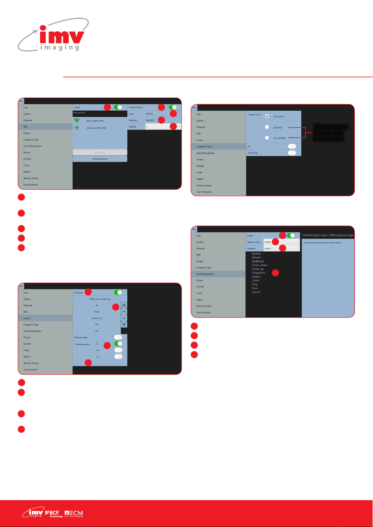
3.4 WiFi Menu
Enable: Activation/deactivation of the WiFi to see available
networks
Hosted Network: Activation/deactivation of the ExaPad‘s
hotspot used to connect an iPad to the scanner
Name: Name of ExaPad‘s hotspot
Password: Password for ExaPad’s Hotspot
Channel: Selection of the WiFi channel (choose the least used
channel to get a better frame rate on the iPad)
Saved WiFi networks will be marked with a star.
3.5 Screen menu
Landscape: If disabled, screen is in Portrait mode
Mode Menu sequencing: The order of how imaging modes
are displayed on main screen can be changed using up and
down buttons
Reduced image: Reduce the size of B image for better
denition
Close menu after: Set time to close menu on left and right side
of the screen (5 to 15 seconds)
3.6 Image & Clips Menu
As default, images and clips are saved as raw data.
3.7 Voice recognition
Commands are only available for B Mode. The list of commands is
displayed in the selected language.
Enable: activation of voice control.
Detection Level: detection lter level
Language: choice of language for voice control
List of words: List of commands
1
2
3
4
5
1 2
3
4
5
1
2
4
3
1
2
3
4
Screen menu
**POINT TO AREA THAT SENTENCE CORRESPONDS TO**
Landscape: If disabled, screen is in Portrait mode
Mode Menu sequencing: The order of how imaging modes are displayed on main screen can be
changed using up and down buttons.
Close menu after: Set time to close menu on left and right side of the screen (5 to 15 seconds)
Reduced image: Reduce the size of B image for better definition
Image & Clips Menu
As default, images and clips are saved as raw data.
**POINT TO .JPG, .DCM AREA**
Other backup formats can be selected
Sorcha Stephens5/6/2019 10:53
Comm ent [8 ]: Screenmenu
Other backup
formats can
be selected
1
2
3
4
1
2
3
4

Instruction manual
www.imv-imaging.com | 7
3.8 Printer
Connect a printer using the USB port on the side of the machine.
Select driver: enables the driver selection for
the installation of a new printer Before installing
a new printer, press “Select driver” and a new
window opens. Search the hard disk or an
external support for the driver of the printer to be
installed and follow the installation procedure.
Default Printer: Selection of default printer when several printers
are connected
Printer Settings: Access to the settings of the printer and printing
parameters.
Install Printer: Adding of a printer with the use of the printer
driver.
3.9 DICOM
In order to be used, the Dicom store and Dicom print must be
correctly congurated with the information obtained from the
Dicom administrator in the premises (clinic/hospital).
Enable DICOM store to send images and clips to the server during
and at the end of an exam. Connection parameters must be
entered correctly otherwise images and clips will be stored locally.
When Dicom Print is activated, images are printed through the
printer server.
3.10 Tools
Follicle Tool: Enables the automatic follicle measurement
tool. After activation, a shortcut will appear in bottom right of
screen to deactivate follicle calculation.
Live: When enabled, follicle measurement can be done when
live scanning. If disabled, Follicle measurement can only be
done freeze mode
Time Integration: Select Long for slow scanning movement
Select Short for fast scanning movement
(measurement less precise)
Two Scan: enables the automatic measurement of two follicles
at the same time on the B Image
Auto Focus: If activated, focus and frequency will change
automatically upon depth adjustments
Keep annotations in Freeze: When enabled, annotations will
re-appear in “Freeze”. Annotation will disappear when the
imaging mode changes, when deleted or when this function is
disabled.
1
1
4
2
3
3
3
2
4
1
2
3
4
5
6
1
2
3
4
5
6

8|
3. Settings
3.10 Report
This switch incorporates the measurement of RVD (Right ventricle
diameter) in the cardio package.
3.11 Remote Access
Remote Access of ExaPad select Display to access (internet
connection is required)
Enter email & password
*For more info, please refer to annex at the end of the instruction
manual
3.12 User Protocol
User Protocols allow you to create specic measurements to be
carried out for each specie you are scanning.
Decide what measurements and tables should be used by creating
a User Protocol.
First select the specie for which you are creating the Protocol, then
select an application from the list. For each application, select
the measurements needed. Give the Protocol a title in the User
Protocol Name box and save.
Delete as necessary.
To select a Protocol while scanning, see section 14 (Protocols:
Page 33).
Enter email & password
*For more info, please refer to annex at the end of the user manual
Enter email & password
*For more info, please refer to annex at the end of the user manual
Select
species
Select application
Select
measurements
and tables for
this protocol
Input
title for
Protocol
Instruction manual
www.imv-imaging.com | 9
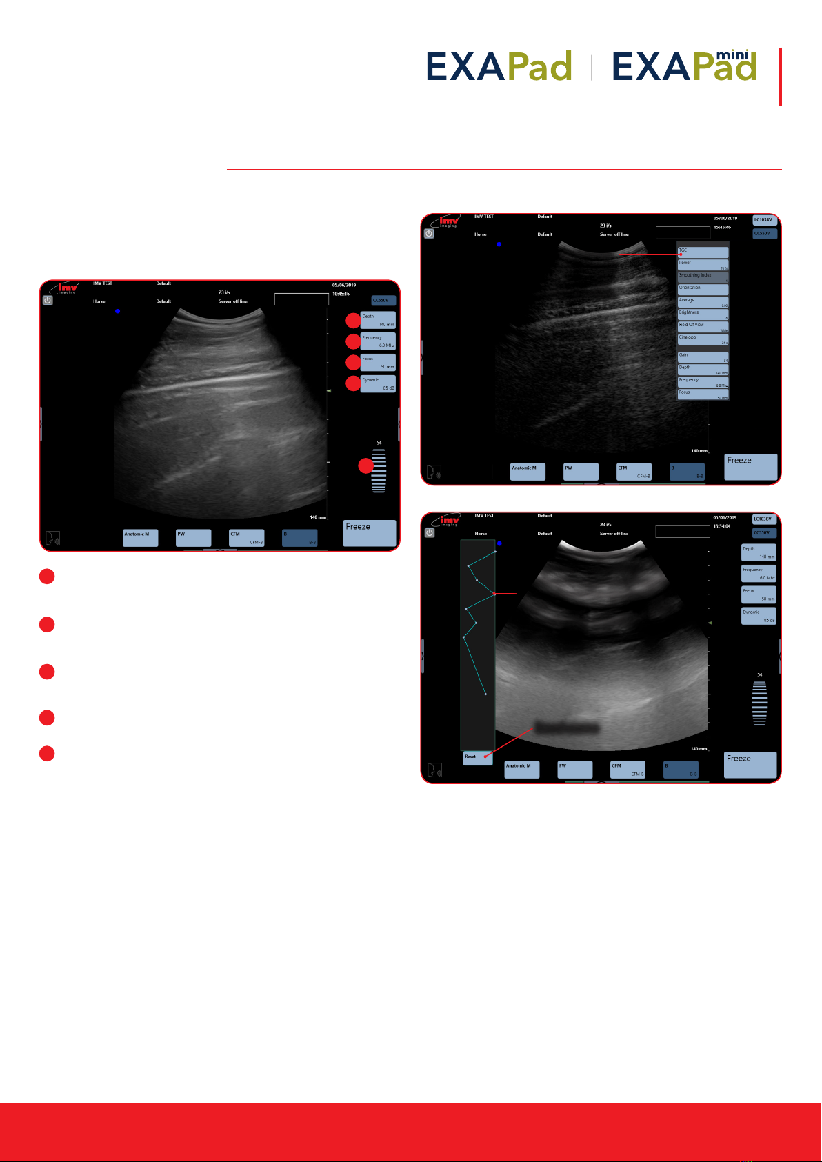
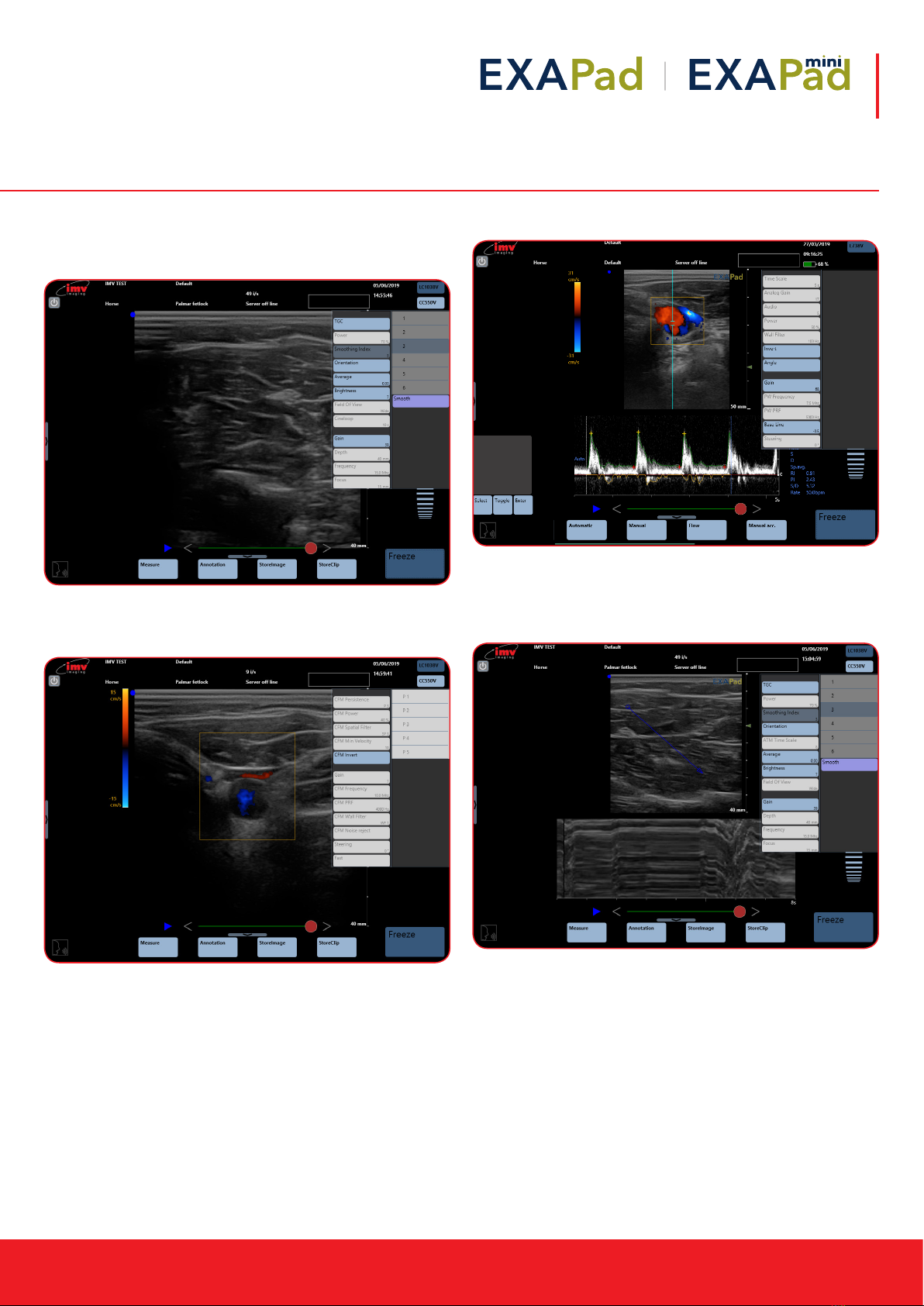
4. B Mode Imaging
The B-mode is the basis for other available modes.
When using one of the combined modes, you can return to the
B-Mode by pressing the button “B”.
The main adjustment parameters for the B-mode are always
displayed on the screen and gives quick access.
Depth: Increase and decrease of the examination depth by
pressing the button “Depth”. Maximum depth varies by probe.
Updated Depth is displayed on depth button.
Frequency: Each probe has 3 frequency settings within its
bandwidth. The updated frequency is displayed on the
frequency button.
Focus: The position of the focal point on screen is adjusted by
the ‘Focus’ button. The updated position of focus is displayed
on the focus button
Dynamic: Increase and decrease dynamic range. The
updated range is displayed on the Dynamic button.
Gain: Scroll up and down to adjust gain. Gain units go from
1-100 and is displayed above the gain scroller.
The advanced adjustment menu is accessible when pressing on
the arrow button on the right side of the screen
4.1 TCG – Time Gain Control
1
2
3
4
5
5
1
2
3
4
Time gain control
curve is displayed
by selecting ‘ON’
on the TGC menu.
Each zone is represented by
a blue dot on the curve. The
number of adjustment markers
depends on the exploration
depth. Move each dot to the
left or right to adjust the time
gain control curve.
Reset curve
10 |
4. B Mode Imaging
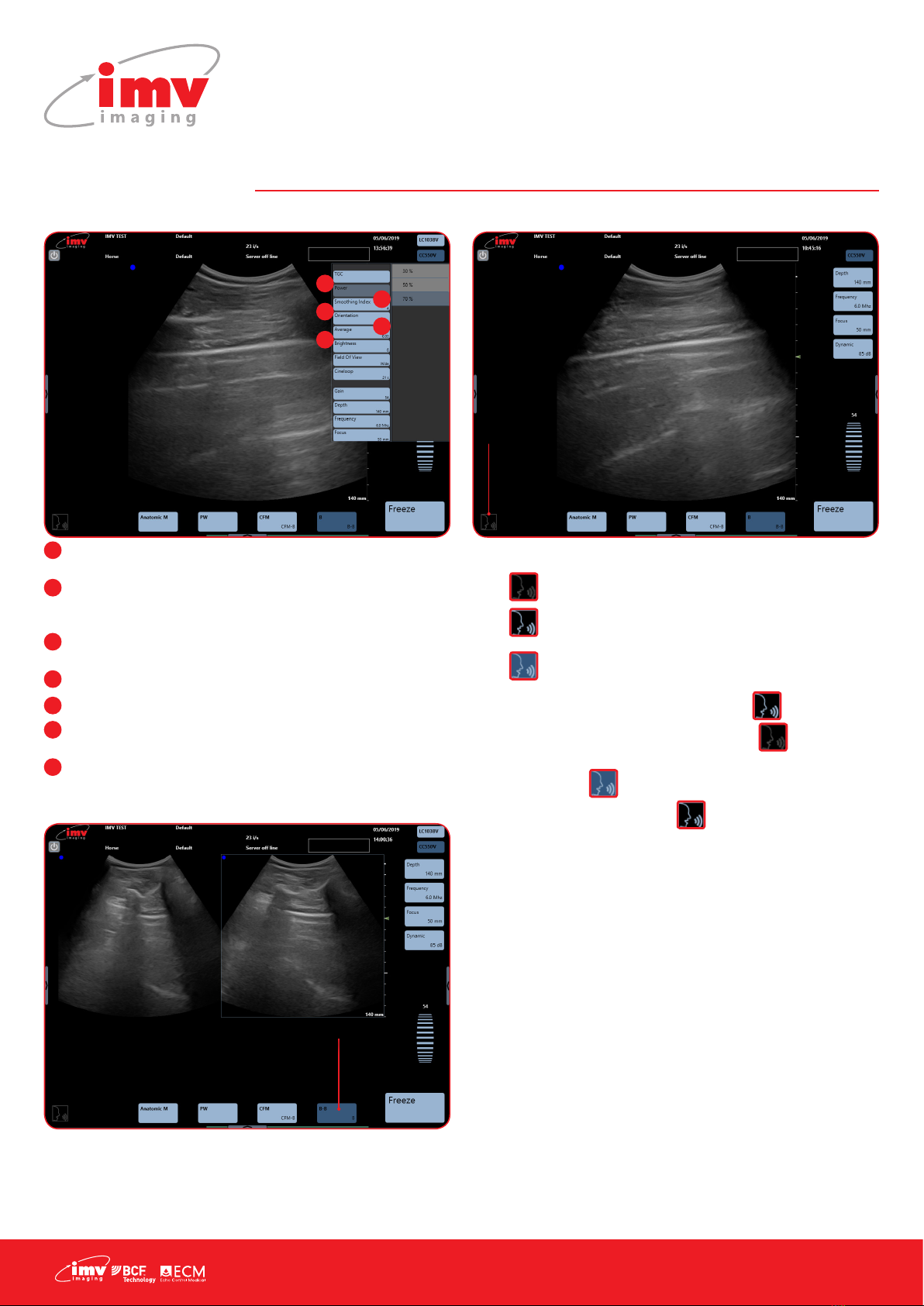
4.2 Other Advanced Adjustments
Power: Emission power adjustment choose between 30, 50, 70
and 100%.
Smooth: Activation or deactivation of Smooth index. The
smaller the index value, the smoother the image. A higher
index value will give a harder image.
Orientation: Turn the image up, down, left or right. Rotate 90°,
180° or 270°. Reset to return to standard parameters.
Average: Time average or temporal smoothing adjustment.
Brightness: Adjust brightness of screen.
Field of view: Adjust the width of the image to regain the fram
rate
Cineloop: Adjust cineloop length, the longer the cineloop the
lower the resolution (See page 16)
4.3 Dual Imaging
The image on the right of the screen is live. Touch the left image in
order to freeze the rst image and activate the second.
When the two images are both frozen, the image that will be live
when touching pressing “Freeze” is the image with a blue edge.
A cineloop is available on the latest sequence of images.
4.4 Voice Command
The voice control has 3 different states:
• : The voice control is not active
• : The voice control is activated and ExaPad waits
for an order
• : ExaPad listens to you
Activate the voice control, this pictogram
The voice control has 3different states:
-: The voice control is not active
-: The voice control is activated and ExaPad waits for an order
-: ExaPad listens to you
Activate the voice control, this pictogram flashes a few times before it replaces the pictogram
. Start by pronouncing “System” to instruct the ExaPad to listen. Wait until the pictogram is
displayed. Pronounce the desired voice control. When the pictogram flashes and is displayed
again, a new request can be pronounced.
Start all voice controls by pronouncing “System”
The following controls are available for voice control:
- « Deeper »: Increase of exploration depth
- « Shallower »: Decrease of exploration depth
- « Focus down »: Deeper Focus
- « Focus up »: More superficial Focus
- « Frequency »: Passing from one frequency to another, circular
- « Higher »: Increase of general gain in B mode (steps of 10 units)
- « Lower »: Decrease of general gain in B mode (steps of 10 units)
- « Stop »: Freeze and unfreeze of image
- « Save » : Storing of current image
- « Cancel »: Cancelling of the last processed voice control
French and Spanish controls also available – see online for instructions.
ashes a
few times before it replaces the pictogram
The voice control has 3different states:
-: The voice control is not active
-: The voice control is activated and ExaPad waits for an order
-: ExaPad listens to you
Activate the voice control, this pictogram flashes a few times before it replaces the pictogram
. Start by pronouncing “System” to instruct the ExaPad to listen. Wait until the pictogram is
displayed. Pronounce the desired voice control. When the pictogram flashes and is displayed
again, a new request can be pronounced.
Start all voice controls by pronouncing “System”
The following controls are available for voice control:
- « Deeper »: Increase of exploration depth
- « Shallower »: Decrease of exploration depth
- « Focus down »: Deeper Focus
- « Focus up »: More superficial Focus
- « Frequency »: Passing from one frequency to another, circular
- « Higher »: Increase of general gain in B mode (steps of 10 units)
- « Lower »: Decrease of general gain in B mode (steps of 10 units)
- « Stop »: Freeze and unfreeze of image
- « Save » : Storing of current image
- « Cancel »: Cancelling of the last processed voice control
French and Spanish controls also available – see online for instructions.
. Start by
pronouncing “System” to instruct the ExaPad to listen. Wait until
the pictogram
The voice control has 3different states:
-: The voice control is not active
-: The voice control is activated and ExaPad waits for an order
-: ExaPad listens to you
Activate the voice control, this pictogram flashes a few times before it replaces the pictogram
. Start by pronouncing “System” to instruct the ExaPad to listen. Wait until the pictogram is
displayed. Pronounce the desired voice control. When the pictogram flashes and is displayed
again, a new request can be pronounced.
Start all voice controls by pronouncing “System”
The following controls are available for voice control:
- « Deeper »: Increase of exploration depth
- « Shallower »: Decrease of exploration depth
- « Focus down »: Deeper Focus
- « Focus up »: More superficial Focus
- « Frequency »: Passing from one frequency to another, circular
- « Higher »: Increase of general gain in B mode (steps of 10 units)
- « Lower »: Decrease of general gain in B mode (steps of 10 units)
- « Stop »: Freeze and unfreeze of image
- « Save » : Storing of current image
- « Cancel »: Cancelling of the last processed voice control
French and Spanish controls also available – see online for instructions.
is displayed. Pronounce the desired voice
control. When the pictogram
The voice control has 3different states:
-: The voice control is not active
-: The voice control is activated and ExaPad waits for an order
-: ExaPad listens to you
Activate the voice control, this pictogram flashes a few times before it replaces the pictogram
. Start by pronouncing “System” to instruct the ExaPad to listen. Wait until the pictogram is
displayed. Pronounce the desired voice control. When the pictogram flashes and is displayed
again, a new request can be pronounced.
Start all voice controls by pronouncing “System”
The following controls are available for voice control:
- « Deeper »: Increase of exploration depth
- « Shallower »: Decrease of exploration depth
- « Focus down »: Deeper Focus
- « Focus up »: More superficial Focus
- « Frequency »: Passing from one frequency to another, circular
- « Higher »: Increase of general gain in B mode (steps of 10 units)
- « Lower »: Decrease of general gain in B mode (steps of 10 units)
- « Stop »: Freeze and unfreeze of image
- « Save » : Storing of current image
- « Cancel »: Cancelling of the last processed voice control
French and Spanish controls also available – see online for instructions.
ashes and is displayed
again, a new request can be pronounced.
Start all voice controls by pronouncing “System”
The following controls are available for voice control:
• Deeper: Increase of exploration depth
• Shallower: Decrease of exploration depth
• Focus down: Deeper Focus
• Focus up: More supercial Focus
• Frequency: Passing from one frequency to another,
circular
• Higher: Increase of general gain in B mode (steps of 10
units)
• Lower: Decrease of general gain in B mode (steps of 10
units)
• Stop: Freeze and unfreeze of image
• Save: Storing of current image
• Cancel: Cancelling of the last processed voice control
French and Spanish controls also available – see online for
instructions.
1
2
3
4
5
1
2
3
4
5
Activate and deactivate
Dual mode from B/B in
imaging modes menu.
Activate
voice
control
The voice control has 3different states:
-: The voice control is not active
-: The voice control is activated and ExaPad waits for an order
-: ExaPad listens to you
Activate the voice control, this pictogram flashes a few times before it replaces the pictogram
. Start by pronouncing “System” to instruct the ExaPad to listen. Wait until the pictogram is
displayed. Pronounce the desired voice control. When the pictogram flashes and is displayed
again, a new request can be pronounced.
Start all voice controls by pronouncing “System”
The following controls are available for voice control:
- « Deeper »: Increase of exploration depth
- « Shallower »: Decrease of exploration depth
- « Focus down »: Deeper Focus
- « Focus up »: More superficial Focus
- « Frequency »: Passing from one frequency to another, circular
- « Higher »: Increase of general gain in B mode (steps of 10 units)
- « Lower »: Decrease of general gain in B mode (steps of 10 units)
- « Stop »: Freeze and unfreeze of image
- « Save » : Storing of current image
- « Cancel »: Cancelling of the last processed voice control
French and Spanish controls also available – see online for instructions.
6
7
Instruction manual
www.imv-imaging.com | 11
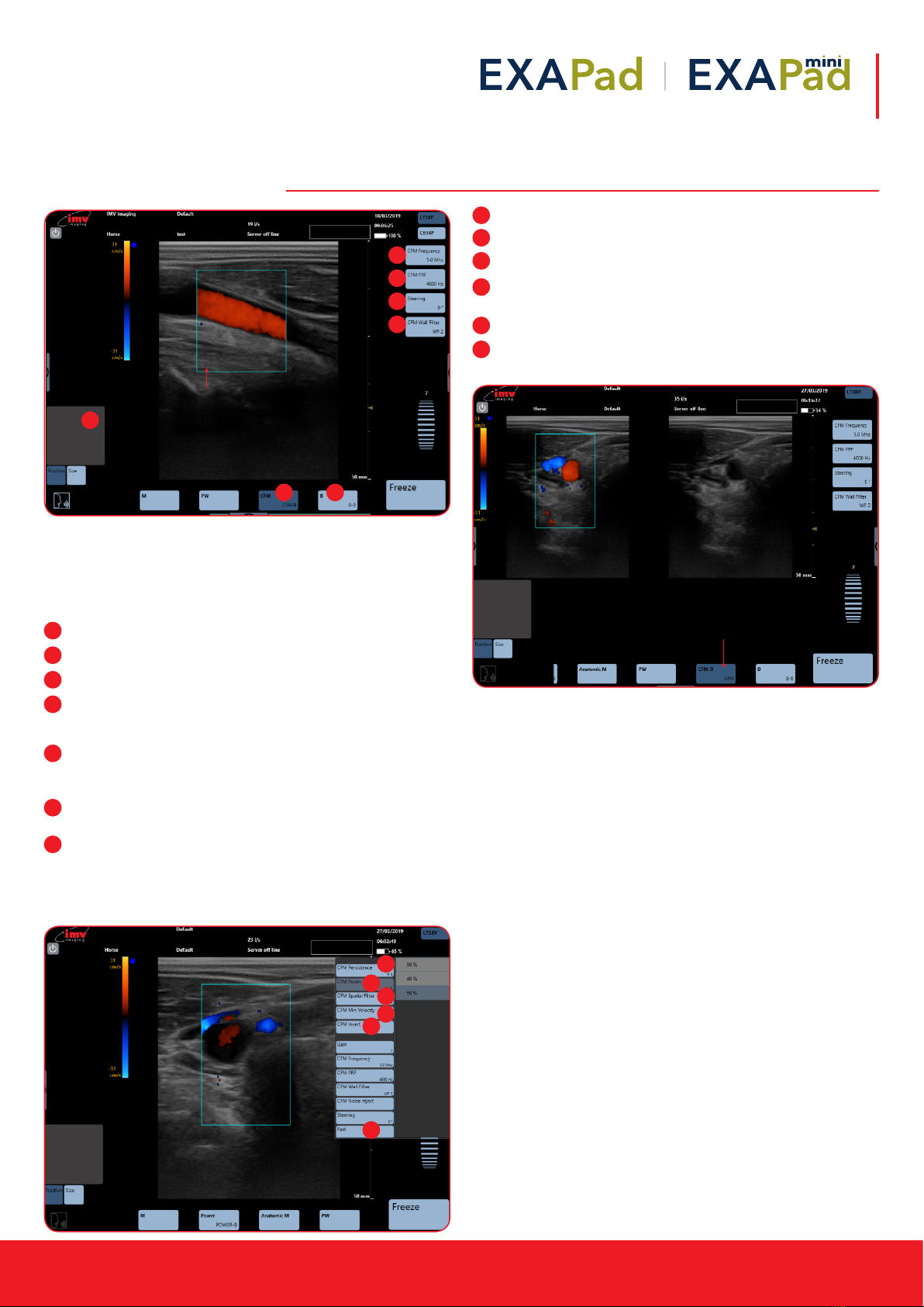
5. CFM Mode imaging
The colour scale which is also the PRF scale is graduated in two
parts in order to distinguish the two directions of the ows: towards
and away from the probe. Slow ows are depicted in dark red or
dark blue; high speeds are passing from blue to white or from red to
yellow (depending on the direction).
CFM: Activation of Colour Flow Mapping added to B image.
B: Deactivation of CFM mode.
CFM Frequency: Adjust CFM Frequency
Position box: Adjust position or size of CFM box. To adjust size,
slide from left to right to enlarge and decrease horizontally and
up and down to enlarge and decrease vertically.
PRF: Adjust Pulse Repetition Frequency in CFM. Updated PRF
value in Hz is displayed and the PRF colour scale in cm/s is
updated on the left of screen.
Steering: The CFM box can be steered using Steering. Only
possible using the linear probe.
Wall Filter: This lter low frequencies linked to vascular wall
movements and not ows. The higher the lter, the more the
low frequencies of circular origin will be removed.
Access the advanced adjustments menu by taping at the left-
hand side of the screen.
Persistence: Adjust persistence
Power: Adjustment of emission power in CFM
Spatial Filter: This lter smooths the colour doppler
Min Velocity: The CFM velocity is on when CFM is activated.
This function denes minimum visible velocity.
Invert: Inversion of the colours in CFM.
Fast: Activation of fast will increase the frame rate.
Deactivation increases resolution.
5. CFM Mode imaging
The colour scale which is also the PRF scale is graduated in two parts in order to distinguish the two
directions of the flows: towards and away from the probe. Slow flows are depicted in dark red or dark
blue; high speeds are passing from blue to white or from red to yellow (depending on the direction).
**POINT TO CFM**
Activation of Colour Flow Mapping added to B image.
**POINT TO B**
Deactivation of CFM mode.
**POINT TO CFM FREQUENCY**
Adjust CFM Frequency
**POINT THE BLUE BOX IN CENTRE OF IMAGE**
The edge of the CFM box is blue when the repositioning is active
**POINT TO THE GREY BOX ON LEFT-HAND SIDE ABOVE POSITION**
Adjust position or size of CFM box.
To adjust size, slide from left to right to enlarge and decrease horizontally and up and down to enlarge
and decrease vertically.
**POINT TO PRF**
Adjust Pulse Repetition Frequency in CFM. Updated PRF value in Hz is displayed and the PRF colour
scale in cm/s is updated on the left of screen.
**POINT TO STEERING**
The CFM box can be steered using Steering. Only possible using the linear probe.
**POINT TO WALL FILTER**
This filter low frequencies linked to vascular wall movements and not flows. The higher the filter, the
more the low frequencies of circular origin will be removed.
The edge of the CFM
box is blue when the
repositioning is active
3
21
4
5
6
7
1
2
3
4
5
6
7
CFM DUAL
**POINT TO CFM-B AT BOTTOM OF SCREEN**
Enabled you to see one image in CFM mode and one in B mode.
Sorcha Stephens5/6/2019 14:04
Commen t [ 2 0 ] : Cfmdual
Enabled you to
see one image in
CFM mode and
one in B mode.
1
2
3
4
5
6
Access the advance adjustments menu by swiping across from the left-hand side of the screen.
**POINT TO POWER**
Adjustment of emission power in CFM
**POINT TO PERSISTENCE**
Adjust persistence
**POINT TO SPATIAL FILTER**
This filter smooths the colour doppler
**POINT TO MIN VELOCITY**
The CFM velocity is on when CFM is activated. This function defines minimum visible velocity.
**POINT TO INVERT**
Inversion of the colours in CFM.
**POINT TO FAST**
Activation of fast will increase the frame rate. Deactivation increases resolution.
2
1
3
4
5
6
12 |
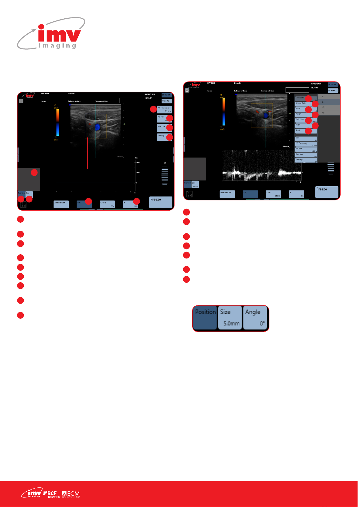
6. PW Mode imaging
6.1 Position and size of the PW gate
PW: Start PW imaging. Activate Pulse Wave, PW specter is
added to the B image.
Frequency: Adjust PW frequency
PRF: Adjust Pulse Repetition Frequency. Updated PRF value in
Hz is displayed in the PRF button on the screen
Base Line: Adjust PW spectrum base line
Steering: Adjust the angle of the PW gate
B: Deactivate Pulse Wave
Position: When activated, the track pad will reposition the PW
gate
Size: When activated, the track pad will resize the PW gate.
Slide up to increase size and down to decrease
Position Box: Track pad
Access the advance adjustments menu by tapping at the right-
hand side of screen.
Time Scale: Adjust PW Time scale
Analog Gain: Adjust analog gain for PW. Different scale from
general gain which is digital gain.
Audio: Adjust audio level
Power: Adjust PW power
Wall Filter: Adjust wall lter. This lter is ltering low frequencies
linked to vascular wall movements
Spectrum Inversion: Display of PW Spectrum can be inversed
Angle: The angle made by the Doppler ring and the
measured ow is activated in the advanced adjustment menu.
When Angle is activated, the angle is displayed on the PW
gate and button “Angle” is available under the trackpad.
Sliding the nger upwards and downwards on the trackpad
adjusts the angle in the direction of the ow in order to
measure the real speed of the ow.
After modifying the size or the position of the PW gate, press
the button “Angle” under the trackpad again in order to
activate the angle adjustment.
1
2
3
4
5
6
7 8
9
The PW gate is
a continuous
line around
the B image
1
2
3
4
5
6
7
8
9
1
2
3
4
5
6
7
1
2
3
4
5
6
7
Instruction manual
www.imv-imaging.com | 13
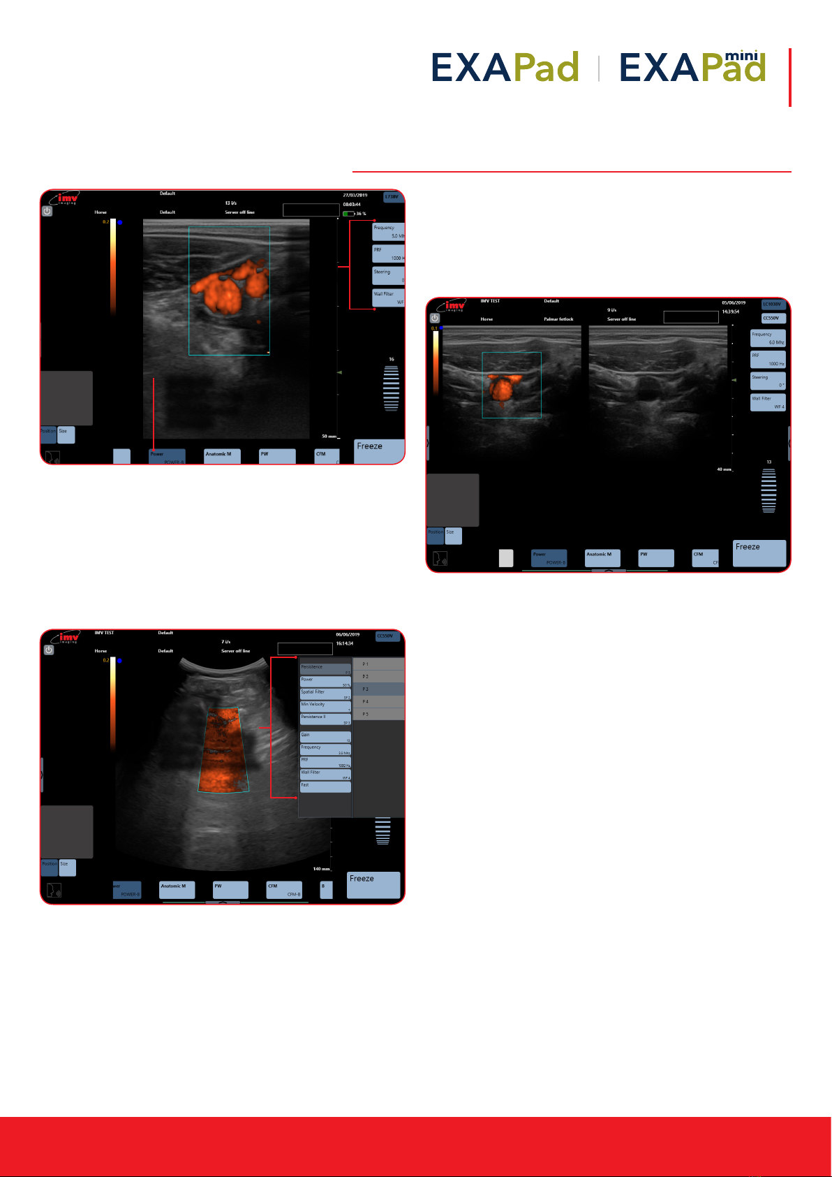
7. Power Doppler Mode imaging
7.1 Position and size of the Power Doppler Box
The Power box can be moved with the trackpad.
To adjust the size, click on the button “Size”, situated under the
trackpad. The edge of the Power box is a blue dotted line when
the size adjustment is active. Slide horizontally on the touch pad to
adjust the width and vertically to adjust the height. After adjusting
the size of the Power box, the active adjustment automatically
returns to the positioning of the box after a short lapse of time.
7.2 Dual Power Doppler
Activation and deactivation of the function Dual Power Doppler by
clicking on the button Power/ Power-B.
The function Dual Power Doppler enables to visualize the same live
image simultaneously in two different modes, one in Power Doppler
mode and one in B mode.
7. Power Mode imaging
**POINT TO POWER AT BOTTOM OF SCREEN**
Activate Power image, added to the B image
**POINT TO THE BLUE ICONS ON LEFT HAND SIDE OF SCREEN**
Main controls for adjusting Power Mode
Position and size of the Power box
The Power box can be moved with the trackpad.
To adjust the size, click on the button “Size”, situated under the trackpad. The edge of the Power box is
a blue dotted line when the size adjustment is active. Slide horizontally on the touch pad to adjust the
width and vertically to adjust the height. After adjusting the size of the Power box, the active
adjustment automatically returns to the positioning of the box after a short lapse of time.
Access the advance adjustments menu by swiping across from the left-hand side of the screen.
POINT OUT ALL ADJUSTMENTS IN ADVANCED ADJUSTMENTS MENU
Sorcha Stephens6/6/2019 15:49
Com m ent [ 23]: Advancedadjustments
powermode
Activate
Power image,
added to the
B image
Main
controls
for
adjusting
Power
Mode
Access the
advanced
adjustments
menu by tapping
at the right-hand
side of the screen.

14 |
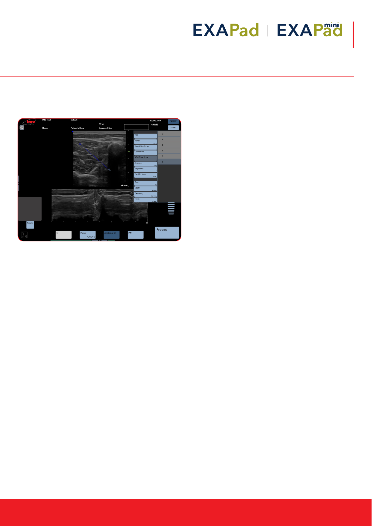
8. M Mode Imaging
To activate M mode imaging by sliding along on the lower menu
and pressing M. The TM spectrum is added to the B image.
8.1 Position and size of the Anatomic M line
See B mode imaging for adjustments available in M Mode imaging
on page 9.
Activation of the Anatomic M mode imaging by pressing the
button Anatomic M. The Anatomic M specter is added to the B
image (B/ anatomic TM).
8.2 Anatomic M Mode imaging
Place the start of the Anatomic M line with the trackpad, then press
Toggle in order to position the arrow that symbolizes the end of the
Anatomic M line specter.
See B mode imaging for adjustments available in M Mode imaging
on page 9.
8. M Mode Imaging
To activate M mode imaging by sliding along on the lower menu and pressing M. The TM spectrum is
added to the B image.
Position and size of the Anatomic M line
**POINT TO GREY BOX ON LEFT HAND SIDE OF SCREEN**
Reposition and size the M line using trackpad
See B mode imaging for adjustments available in M Mode imaging on PAGE X
Sorcha Stephens6/6/2019 12:19
Comm en t [2 5] : Can’tgetbetterimages
rightnow–willtrysource
8. M Mode Imaging
To activate M mode imaging by sliding along on the lower menu and pressing M. The TM spectrum is
added to the B image.
Position and size of the Anatomic M line
**POINT TO GREY BOX ON LEFT HAND SIDE OF SCREEN**
Reposition and size the M line using trackpad
See B mode imaging for adjustments available in M Mode imaging on PAGE X
Sorcha Stephens6/6/2019 12:19
Co m m ent [25]: Can’tgetbetterimages
rightnow–willtrysource
Reposition
and size the
M line using
trackpad
Reposition
and size the
M line using
trackpad
Instruction manual
www.imv-imaging.com | 15
8.3 Time scale in Anatomic TM mode
The adjustment of the time scale in Anatomic TM mode is made in
in the advanced adjustment menu, accessed by tapping at the
right-hand side of the screen.

16 |
9. Freeze Mode and Cineloop
Freeze mode is available in all imaging modes.
Freeze: Freeze and unfreeze the live ultrasound image
ExaPad: Indicates that the image is Frozen
9.1 Cineloop
The length of the sequence depends on the imaging mode and on
the frame rate.
plays cineloop sequence
pause cineloop sequence
previous image in sequence
next image in sequence
use to scroll through the sequence of images
It is possible to select the start and the end of the cineloop that
should be saved.
Double-click on the red marker (that will be surrounded by a blue
line), move the red curser until the last image in the sequence you
want to store.
Store Clip: Save the selected sequence
Store Image: Save selected image
Images and clips are saved on the hard-disk of the scanner.
9.2 Post-processing
In Freeze mode, all functions available in post-processing are
active.
Post-processing controls are available on cineloop images &
sequences as well as on stored images and sequences.
1
2
1
2
Cineloop
cursor, scroll
through series of
previous images
Freeze
Menu
Adjust time length
of cineloop
from advanced
adjustments
menu in B mode;
10/20/30/40
seconds
plays cineloop sequence
pause cineloop sequence
previous image in sequence
next image in sequence
use to scroll through the sequence of images
It is possible to select the start and the end of the cineloop that should be saved.
Double-click on the red marker (that will be surrounded by a blue line), move the red curser until the
last image in the sequence you want to store.
**POINT TO STORE CLIP**
Save the selected sequence
**POINT TO STORE IMAGE**
Save selected image
Images and clips are saved on the hard-disk of the scanner.
**POINT TO CINELOOP**
Adjust time length of cineloop from advanced adjustments menu in B mode;
10/20/30/40 seconds
Sorcha Stephens5/6/2019 14:48
Comm ent [30]: Usefreezecrop1and
freezecrop2
Sorcha Stephens5/6/2019 14:50
Comm ent [31]: Cineloop
plays cineloop sequence
pause cineloop sequence
previous image in sequence
next image in sequence
use to scroll through the sequence of images
It is possible to select the start and the end of the cineloop that should be saved.
Double-click on the red marker (that will be surrounded by a blue line), move the red curser until the
last image in the sequence you want to store.
**POINT TO STORE CLIP**
Save the selected sequence
**POINT TO STORE IMAGE**
Save selected image
Images and clips are saved on the hard-disk of the scanner.
**POINT TO CINELOOP**
Adjust time length of cineloop from advanced adjustments menu in B mode;
10/20/30/40 seconds
Sorcha Stephens5/6/2019 14:48
Comment [30]: Usefreezecrop1and
freezecrop2
Sorcha Stephens5/6/2019 14:50
Comment [31]: Cineloop
plays cineloop sequence
pause cineloop sequence
previous image in sequence
next image in sequence
use to scroll through the sequence of images
It is possible to select the start and the end of the cineloop that should be saved.
Double-click on the red marker (that will be surrounded by a blue line), move the red curser until the
last image in the sequence you want to store.
**POINT TO STORE CLIP**
Save the selected sequence
**POINT TO STORE IMAGE**
Save selected image
Images and clips are saved on the hard-disk of the scanner.
**POINT TO CINELOOP**
Adjust time length of cineloop from advanced adjustments menu in B mode;
10/20/30/40 seconds
Sorcha Stephens5/6/2019 14:48
Commen t [3 0 ]: Usefreezecrop1and
freezecrop2
Sorcha Stephens5/6/2019 14:50
Commen t [3 1 ]: Cineloop
plays cineloop sequence
pause cineloop sequence
previous image in sequence
next image in sequence
use to scroll through the sequence of images
It is possible to select the start and the end of the cineloop that should be saved.
Double-click on the red marker (that will be surrounded by a blue line), move the red curser until the
last image in the sequence you want to store.
**POINT TO STORE CLIP**
Save the selected sequence
**POINT TO STORE IMAGE**
Save selected image
Images and clips are saved on the hard-disk of the scanner.
**POINT TO CINELOOP**
Adjust time length of cineloop from advanced adjustments menu in B mode;
10/20/30/40 seconds
Sorcha Stephens5/6/2019 14:48
Comment [30]: Usefreezecrop1and
freezecrop2
Sorcha Stephens5/6/2019 14:50
Comment [31]: Cineloop
plays cineloop sequence
pause cineloop sequence
previous image in sequence
next image in sequence
use to scroll through the sequence of images
It is possible to select the start and the end of the cineloop that should be saved.
Double-click on the red marker (that will be surrounded by a blue line), move the red curser until the
last image in the sequence you want to store.
**POINT TO STORE CLIP**
Save the selected sequence
**POINT TO STORE IMAGE**
Save selected image
Images and clips are saved on the hard-disk of the scanner.
**POINT TO CINELOOP**
Adjust time length of cineloop from advanced adjustments menu in B mode;
10/20/30/40 seconds
Sorcha Stephens5/6/2019 14:48
Co mmen t [30 ]: Usefreezecrop1and
freezecrop2
Sorcha Stephens5/6/2019 14:50
Co mmen t [31 ]: Cineloop
12
1
2
Instruction manual
www.imv-imaging.com | 17
9.3 Post-processing in B mode
The post-processing is made by the advanced adjustment menu in
B mode.
Functions in white are not available for Post-processing
9.4 Post-processing in CFM mode
In CFM, only the inversion of colors is available for post-processing.
9.5 Post-processing in PW mode
The post-processing is made by the advanced adjustment menu in
PW mode.
9.6 Post-processing in Anatomic TM mode and
TM mode
Functions in white are not available for Post-processing.
Post-processing in PW mode
In PW mode, only the inversion of the spectrum and the adjustment of the angle are available for post-
processing
Post-processing in Anatomic TM mode and TM mode
Functions in white are not available for Post-processing.
Annotations
When the image is frozen, the button “Annotation” is accessible.
It is also possible to enter annotations on a live image or when making measurements as shown below:
Sorcha Stephens5/6/2019 15:19
Com me n t [34 ]: post-processinginPW
mode
Sorcha Stephens5/6/2019 15:02
Com me n t [35 ]: post-processinganatomic
M
Sorcha Stephens5/6/2019 15:02
Com me n t [36 ]: Annotationcrop
Freezecrop1
Showthatyouwwipeupanddownbetween
thetwomenus
18 |
9.7 Annotations
When the image is frozen, the button “Annotation” is accessible.
It is also possible to enter annotations on a live image or when
making measurements as shown below:
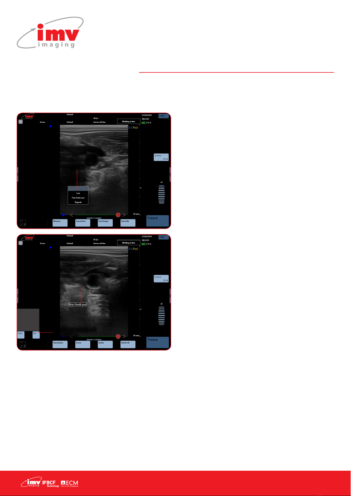
9.8 Entering text
Click on the button “Annotation”, place the text box with the
trackpad, click on the button “Edit”. This will display a keyboard
on the screen. Enter the text and conrm by clicking Enter on the
keyboard, or long click on the empty annotation, and a predened
list appears.
The button “Select”, under the trackpad, enables to select a text
zone, surrounded by a white rectangle, in order to reposition it and/
or modify the entered text by clicking “Edit” again.
9.9 Annotated arrow
Click on the button “Arrow”. A caliper is displayed, this will be the
tip of the arrow. Place the text zone on the wanted place with the
trackpad. “Edit”. This will display a keyboard on the screen. Enter
the text and conrm by clicking Enter on the keyboard.
The button “Select”, under the trackpad enables to select an
annotation, the button “Toggle” enables repositioning for either the
tip of the arrow or the associated text zone.
9.10 Delete
“Delete” will delete the last entered annotation (text or annotated
arrow).
“Delete All” will delete all annotations on the screen.
9. Freeze Mode and Cineloop
Instruction manual
www.imv-imaging.com | 19
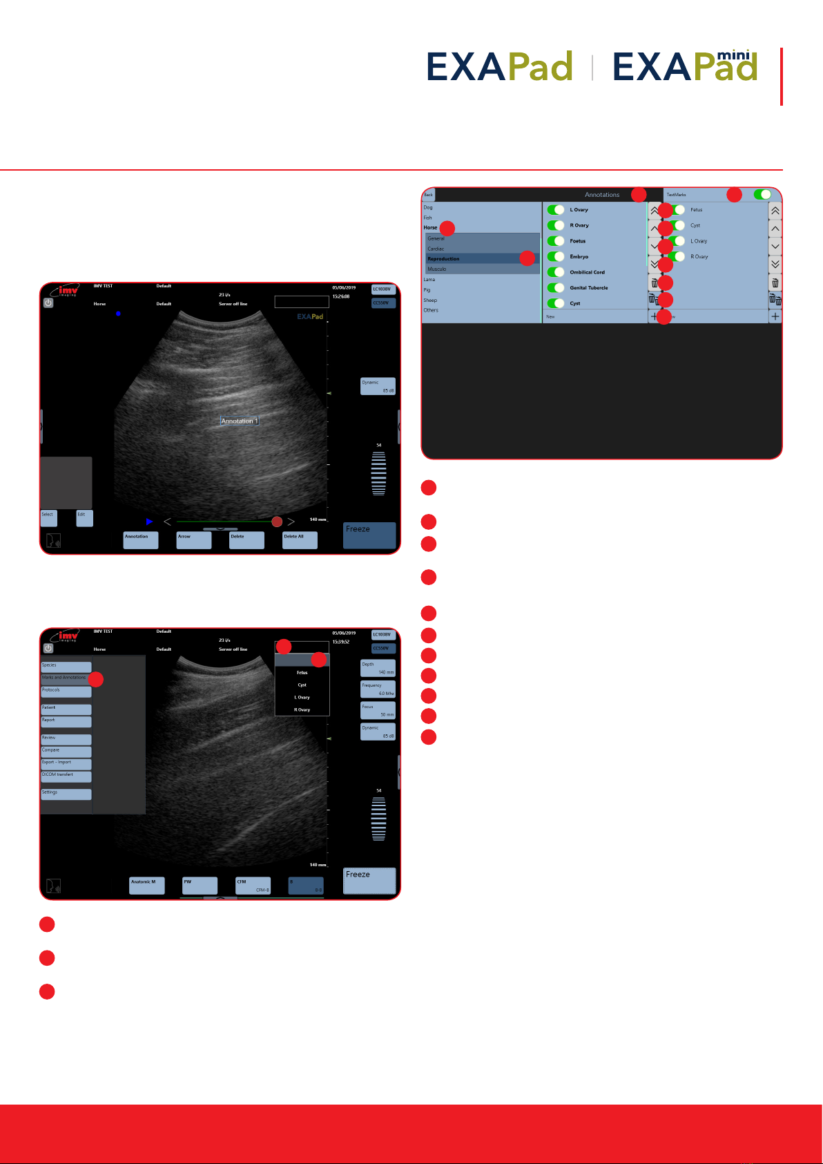
9.11 Marks and annotations
Each image can be tagged with marks or annotations. There are
predened factory annotations or user specic.
A mark is a text that will not be deleted from the screen when the
image is unfrozen.
A user or predened annotation will be deleted when the image
is unfrozen, except if the keep annotation in freeze is activated in
Settings (see Settings: Page 5).
Marks and annotations: Set up of markers and predened
annotations by tapping at the left-hand side of the screen.
Use of predened marks: The marks can be used on live or
frozen images.
A free text can also be entered as a mark
Horse: For each specie and application, you can edit user
annotations. Some factory presets will already exist.
Reproduction: Current specie and application are in bold
Annotations: Predened list of annotations or marks for current
application
Textmarks: Create predened Text Marks and put the Text Mark
Box at the top of the ultrasound image
places the selected annotation in the rst position
places the selected annotation higher
places the selected annotation lower
places the selected annotation in the last position
deletes the selected annotation
Deletes all annotations except for the factory exam
validates a new annotation
1
2
3
1
2
3
1
2
3
4
5
6
7
8
9
10
11
1
2
3 4
5
6
7
8
9
10
11
20 |
9.12 Predened annotations
When the image is live, all predened annotations are deleted
from the screen (except if the option “Keep annotation in freeze” is
activated in the settings – see Settings-Tools)
9. Freeze Mode and Cineloop
Long press on a frozen
image to access list of
predened annotations.
Select annotation
If annotation is
surrounded by a white
rectangle, you can
reposition the annotation
with the trackpad.
Modify predened
annotation
This manual suits for next models
1
Table of contents


