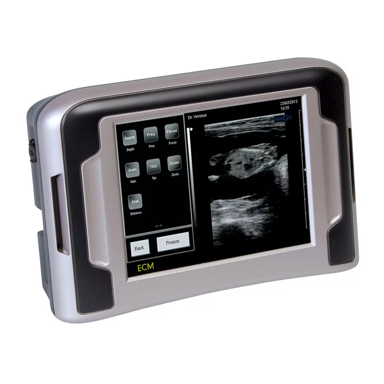
IMV EXAGO User manual

1
www.imv-imaging.com |
Your complete animal imaging solution
Instruction
manual

Exago
Manual
2
12
19
22
13
20
23
24
25
9
8
16
10
17
11
18
3
Contents
5
6
7
1. Safety instructions .....................................................................................................
2. Getting started ..........................................................................................................
3. Keyboard functions ...................................................................................................
4. B mode and menu .....................................................................................................
8
5. CFM mode and menu ...............................................................................................
9
6. PW mode and menu .................................................................................................
9
7. Measure menu ...........................................................................................................
8. Review menu .............................................................................................................
9. Probe menu ...............................................................................................................
10. Settings .....................................................................................................................
11. Protocol menu ..........................................................................................................
12. Report menu ............................................................................................................
13. Patient menu ............................................................................................................
14. Screen icons ............................................................................................................
15. Cleaning and disinfection instructions ..................................................................
16. Probe types and corresponding applications .......................................................
17. Specications ...........................................................................................................
18. Third party suppliers´compatibility ........................................................................
19. Service centres ........................................................................................................

Exago
Manual
Exago
Manual
3
www.imv-imaging.com |
Type BF patient applied part (B=body,
F=oating applied part). The probe com-
plies with the class “BF” Medical Electric
equipment compliant with he standard
IEC 60601-1
Warning: Read the user manual before
using the device bearing this symbol
Warning : Do not sit on the equipment
Warning : Do not push the equipment if
the castor wheels are locked
ON / OFF switch
Collect separately from other waste
(see European Commission Directive for
electronic waste). The device must be
recycled at the certied recycling center.
CE Mark
1.1 Safety symbols
Please note the meaning of the following
safety symbols:
1.2 Environmental conditions of use
The device shall be operated in a clean
atmosphere, without dust and smoke.
The device is designed and tested be ope-
rated within this range of temperature:
• -20°C to +60°C during transportation
and storing
• +10°C to +40°C during operation.
The device is designed to be operated
with a relative humidity range from 10 to
95% including condensation.
The device is designed for the following
atmospheric pressures:
• 700 hPa to 1060 hPa while in operation
• 500 hPa to 1060 hPa during transporta-
tion and storing.
1.3 Electrical safety
This equipment is compliant with IEC stan-
dard 60601-1, Safety for Medical Electrical
Equipment.
According to the standard, the equipment
is classied as:
a) According to the type of protection
against electrical shock:
Class I equipment
b) According to the degree of protec-
tion against electrical shock:
Type BF
c) According to the degree of protec-
tion against harmful water ingress:
IPX0 (device without protection
against water ingress)
d) According to the degree of safety
of application in presence of am-
mable anaesthetic mixture with air,
oxygen or nitrous oxide, device not
suitable for use in the presence of a
ammable anaesthetic mixture with
air, oxygen or nitrous oxide.
e) According to the mode of opera-
tion: Continuous operation
In order to ensure patient safety, please
observe these warnings:
The equipment must be supplied by using
the provided power cord including a con-
nection to ground.
The equipment must be used with the
power adapter supplied by IMV Imaging,
reference Protek PMP120-13-2-B2. The use
of any other power adapter is forbidden.
1.Safety instructions

Exago
Manual
4
1.4 Battery
The equipment uses an internal Lithium
battery. The battery should exclusively be
replaced in the equipment by the identical
type of battery provided by IMV Imaging.
Replacing the battery by an incorrect type
may cause excessive temperatures, re
or explosion. The Battery is a Lithium-Ion
Polymer battery rating a voltage of 14.8 V
and a capacity of 8400 mAh.
1.5 Surface temperatures
The probes provided with the device are
compliant with the security standards con-
cerning surface temperatures. The probes
have been designed in order to never let
the surface temperature exceed 41°C.
The Exago device has not been designed
to be used together with a high frequency
surgical device. A risk of patient burn might
exist in case of failure in connection of
the neutral electrode of the surgical high
frequency device.
1.6 Probe safety
The probes supplied with the Exago equi-
pment are intended to be used only with
IMV imaging systems.
Never try to connect the supplied probes
to any other ultrasound system. This can
lead to irreversible damage on the probe
connector and to the possibility of much
higher acoustic output than required. This
can also lead to patient burn due to over-
heating of the probe.
For safety and maintenance reasons,
never disconnect a probe from the device
without freezing the system rst.
All probes provided with the Exago device
are compliant with the standard ISO 10993-
1 concerning biocompatibility of compo-
nents used for probe manufacturing.
1.7 Other devices connection
The Exago equipment can be connected
to several peripherals like:
• composite video printers
• USB peripherals (ash stick)
• External screen (DVI connection)
To ensure the electrical safety of the equi-
pment:
All peripherals requiring a power input
(printers, monitors etc.) must also use a
medical isolation transformer or comply
themselves with the electrical safety stan-
dard EN 60601-1. Otherwise, the patient
electrical safety is no longer ensured.
This equipment can cause electromagne-
tic perturbations and alter the behaviour of
another equipment. It may be needed to
move the equipment or change his orien-
tation in order to reduce this perturbation.
Always place the probe in the probe
holder on the trolley or in another secured
place when not used in order to avoid it
from falling either on the patient or on the
oor. Any crack or damage to the probe
head can lead to electrical shock. Never
use a probe that is damaged, that has
been dropped or has suffered a severe
collision until it has been inspected by an
IMV Imaging customer service engineer.
Do not immerse the transducer connector
in any liquid. Immersing it can destroy its
electrical safety features.
1
1

Exago
Manual
Exago
Manual
5
www.imv-imaging.com |
2.1 Connection and disconnection of
probes
To connect a probe, put the probe con-
nector in the opening provided for this
purpose (Pic. 1). Turn the locker situated in
the middle of the connector with a slight
pressure in order to engage the locking
mechanism. When the locking mechanism
is engaged, make quarter turn so that the
probe is connected.
After connecting a probe, always place
the probe in a safe place (in one of the
probe holders if the system is used with its
trolley) in order to avoid any damage of
the probe due to a shock or falling down.
Before disconnecting the active probe,
make sure to freeze the image.
To disconnect a probe, make a quarter
turn in order to unlock the connector. Take
the connector out of the device and store
the probe in an appropriate place protec-
ted from shocks.
When starting the device, always make
sure to have a probe connected on the
connector.
2.2 Use of Exago trolley
If the equipment is used with the Exago
trolley, check that a probe is connected to
the right hand side connector.
2.3 Starting of the device
To start/stop the equipment, turn on the
power switch situated on back panel of
the device (Pic. 2)
Then wait until the system starts and dis-
plays the user interface on the screen.
The Exago equipment starts in B mode
with the probe connected. If no probe is
connected, the system will display a label
“No probe”. In this case, connect a probe
to the connector and press “Freeze”, or
restart the equipment.
2.4 Battery operation
The Exago battery can be removed from
the equipment by pressing the two clips
located on the rear of the product. When
inserting the battery back in the device,
check that it is securely fastened. (Pic.1)
When the device is powered by the mains,
the battery is charging whether the device
is on or not. While the battery is charging,
a charging indicator is visible on the back
panel of the device.
2.Getting started
Probe connector
Charging
indicator
Power on/off
Pic.1
Pic.2
Battery
slot

Exago
Manual
6
3.Keyboard functions
F 1 ! 2 @ 3 ?4 +5 % 6 - 7 &8 / 9 ( 0 )
TAB Q W E R T Y U I O P DELETE
CAPS A S D F G H J K L ENTER
SHIFT Z X C V B N M ;
TEXT PICTO
A
RROW
PATIENT REPORT PROTOCOLPROBE ZOOM TGC
SETTINGS CLEAR
FREQUENCY
FOCUS
M CINELOOP
PWD MEASURE REVIEW
CFM
B
SELECT
DEPTH
GAIN
DEPTH
GAIN
FREEZE
UPDATE STORE
Keys to navigate through the
menu on screen
Shortcut to user dened an-
notation with (1-9 as free text)
Arrow in active imaging
mode or calipers in
Freeze. Use “ Clear” to
delete or Arrow in Freeze.
Scroll text lists,
move cursor
or adjust po-
sition of CFM/
PW box.
M Mode
Select to start M
mode. Update to
return to M Line
adjustment.
In Freeze mode move to
previous Cineloop image.
Current image index is
displayed on screen.
Measure menu. Touchpad used for menu selection, mea-
surement cursors, validation of measure-
ments, line positioning in M mode etc.
Used to conrm selection items and activate. Active CFM/PW & M mode, zoom.
Store image
Review the
image/clips.
B Mode menu
CFM Mode menu
PWD Mode menu
When PW is activated from CFM, the “Up-
date” key allows to come back to the CFM
mode with the gate active.
Freeze and unfreeze
the system
Report menu
Protocol menu
Cine loop records or
allows to view clips
Access frequency
selection menu.
Probe menu.
Press select to display
zoomed image or exit zoom.
Patient menu.
Settings menu.
Use keys to
adjust focus.
Reset to
return to initial
TGC level.
Clear annotations,
arrows, biopsy
guide or noise
rejection.

Exago
Manual
Exago
Manual
7
www.imv-imaging.com |
Use keys “Next/Previous to move
through the menu.
Dote indicates the active image and the direction of the image
in L/R, Up/Down.
Probe
Labels displaying settings of the
menu e.g
Dyn-Dynamic
Brigh-Brightness
Freq-Frequency
FAvg-Frame avearage
Date, Time
Battery capacity
4.B mode and menu
F 1 ! 2 @ 3 ?4 +5 % 6 - 7 &8 / 9 ( 0 )
TAB Q W E R T Y U I O P DELETE
CAPS A S D F G H J K L ENTER
SHIFT Z X C V B N M ;
TEXT PICTO
A
RROW
PATIENT REPORT PROTOCOLPROBE ZOOM TGC
SETTINGS CLEAR
FREQUENCY
FOCUS
M CINELOOP
PWD MEASURE REVIEW
CFM
B
SELECT
DEPTH
GAIN
DEPTH
GAIN
FREEZE
UPDATE STORE
B mode and menu, exit Dual mode
Switch between left and
right images in Dual mode
Keys to change settings of the contex-
tual menu.
Noise reject window positioning
adjustment
Exit Noise Rejector Biopsy
PowerDynamic Dynamic Range of B
image.
Transmit Power.
Adjust Brightness.
Brightness Dual
L/R, U/D Frame Average
Noise Reject
Compare two images
in B mode.
Image orientation (Left/
Right or Up/Down).
Select: SLOW, SLMED,
MFAST, FAST values.
Signals will lter to provide
the cleaner image. Exa Cross Cross Beam function.
Used with linear pro-
be only.
Large image Images use maximum
screen in B and Dual mode. Smooth Active in B and Dual
mode. Can be saved
in preset.
Biopsy* Activate biopsy needle on the screen indi-
cating where the needle should travel.
* Before using this feature, test this function in a water tank before use on
a patient. The mechanical tolerance of the biopsy guide may exceed the
expected values and the guiding channel . Press Biopsy or Clear to remove it. Needle guide only works with recommended IMV Imaging guide
for probe. Check that biopsy guide and needle is properly attached to the probe.

Exago
Manual
8
Exago
Manual
Use keys under “Next/Previous to move
along the menu.
CFM box position or size can be adjusted using Touchpad or
Cursor keys in Pre-trace CFM mode.
Probe
Labels displaying settings of the menu
Date, Time
Battery capacity
5.CFM mode and menu
F 1 ! 2 @ 3 ?4 +5 % 6 - 7 &8 / 9 ( 0 )
TAB Q W E R T Y U I O P DELETE
CAPS A S D F G H J K L ENTER
SHIFT Z X C V B N M ;
TEXT PICTO
A
RROW
PATIENT REPORT PROTOCOLPROBE ZOOM TGC
SETTINGS CLEAR
FREQUENCY
FOCUS
M CINELOOP
PWD MEASURE REVIEW
CFM
B
SELECT
DEPTH
GAIN
DEPTH
GAIN
FREEZE
UPDATE STORE
CFM mode and menu.
Press Select to switch from Pre-trace
CFM to Active CFM.
Keys to change settings of the menu.
Steering of CFM box on a linear probe.
Press Update to switch from Active
CFM mode to Pre-trace CFM mode.
Power CFM transmit Power.
Rejection of movements
from vessel walls and
tissues. High Wall Filter, slow
speeds are rejected
Wall Filter
Persistence Frame averaging
on CFM image.
MinVelocity Rejects the color on slow
velocities. A high Min Ve-
locity index cuts the color
and slows velocity
Spatial Filter Smoothening of the
CFM image.
Vessel Size Optimization of colour
sensibility according to the
vessel size.
Invert Inversion of the colour.
CFM scale colour is
also inverted.
Packet Size High index increases CFM
sensitivity and decreases
CFM frame rate.
PRF
Select proper value depen-
ding on the speed of the
measured ow
Burst High index increases
CFM sensitivity and
decreases CFM
spatial resolution.
Labels displaying settings of the menu
in CFM mode e.g. WFillter- Wall Filter,
VesSize-Vessel Size, SFilter-Spatial Filter.
Active CFM contextual menu:
CFM gain adjustment.

Exago
Manual
Exago
Manual
9
www.imv-imaging.com |
Exago
Manual
Use keys under “Next/Previous to move
along the menu.
Active PW mode
Probe
Labels displaying settings of the
menu e.g
WFilter-PW Wall Filter
Power label- Power
Date, Time
Battery capacity
6.PW mode and menu
F 1 ! 2 @ 3 ?4 +5 % 6 - 7 &8 / 9 ( 0 )
TAB Q W E R T Y U I O P DELETE
CAPS A S D F G H J K L ENTER
SHIFT Z X C V B N M ;
TEXT PICTO
A
RROW
PATIENT REPORT PROTOCOLPROBE ZOOM TGC
SETTINGS CLEAR
FREQUENCY
FOCUS
M CINELOOP
PWD MEASURE REVIEW
CFM
B
SELECT
DEPTH
GAIN
DEPTH
GAIN
FREEZE
UPDATE STORE
Cancel Steering, Angle correction in
Pre-trace or PW mode.
Press Update to switch from Active PW
mode to Pre-trace PW mode. When
PW is activated from CFM mode, the
Update key allows to come back to
CFM mode with the gate active.
Select Gate Size and Steering angle
(linear probes only).
PW gain adjustment with the “Gain”
Press Select to return to Active PW mode.
PRF Select value.
Power Transmit Power.
Select the spectrum. The
frequency/velocity is upda-
ted on display.
Baseline
Invert Invert the frequency/velo-
city scale. It is updated on
display.
Audio Audio output volume.
Filter PW Wall Filter. Adjust PW gate position and size on
the B image or B/CFM image and
adjust Steering,Gate size and Angle
parameters before starting PW active
mode. Use Select and Update to
switch between Active and Pre-trace
PW mode.
Pre-trace PW mode

Exago
Manual
10
Exago
Manual
Contexual menu of the measure menu.
Freeze the system and access Measure menu. It will automati-
cally initiate a rst Distance measurement.
Probe
Labels displaying settings of the menu
Date, Time
Battery capacity
7.Measure menu
F 1 ! 2 @ 3 ?4 +5 % 6 - 7 &8 / 9 ( 0 )
TAB Q W E R T Y U I O P DELETE
CAPS A S D F G H J K L ENTER
SHIFT Z X C V B N M ;
TEXT PICTO
A
RROW
PATIENT REPORT PROTOCOLPROBE ZOOM TGC
SETTINGS CLEAR
FREQUENCY
FOCUS
M CINELOOP
PWD MEASURE REVIEW
CFM
B
SELECT
DEPTH
GAIN
DEPTH
GAIN
FREEZE
UPDATE STORE
Access measure menu and exit menu. .
Keys to change settings of the menu.
Use Touchpad to adjust caliper posi-
tioning and validation. Terminate the
measurement. Draw Trace countour.
Distance Four distances can be acquired on the same image. Choose distan-
ce in sequence in Tools to display the next caliper measurement. Four
distances can be acquired on the same image.
Two ellipses can be measured on the same image.
Ellipse
Trace If the trace is not closed, a straight line will be used to close it. It allows
surface/parameter calculation.
Select Selected item and related measurements are highlited.
Delete Delete selected measurements on screen.
Adjust the calipers positioning with
Touchpad and Select.
Press Select to go back to the previous
caliper adjustment.
Measurements are displayed on the
screen with identication and color code

Exago
Manual
Exago
Manual
11
www.imv-imaging.com |
Exago
Manual
Review display includes the images
and clips list. System will explore USB
before exploring the internal memory.
In order to access to internal memory,
remove any connected USB device.
8.Review menu
F 1 ! 2 @ 3 ?4 +5 % 6 - 7 &8 / 9 ( 0 )
TAB Q W E R T Y U I O P DELETE
CAPS A S D F G H J K L ENTER
SHIFT Z X C V B N M ;
TEXT PICTO
A
RROW
PATIENT REPORT PROTOCOLPROBE ZOOM TGC
SETTINGS CLEAR
FREQUENCY
FOCUS
M CINELOOP
PWD MEASURE REVIEW
CFM
B
SELECT
DEPTH
GAIN
DEPTH
GAIN
FREEZE
UPDATE STORE
Access Review menu for reviewing
images and clips.
Keys to change settings of the contex-
tual menu.
Use Touchpad to select le or clip.
Exit Exit review menu.
For loaded clips
Store clip Store current clip.
Delete Delete image/clip.
Load Display the selected ima-
ges or clips. Load images in
cineloop to make or adjust
measurements in post-pro-
cessing. Press freeze to exit
this mode.
First image Display the rst ima-
ge of the selected
clip.
Play/Pause Play or pause the
reading of the selec-
ted clip.
Rename Rename image/clip. Last image Display the last ima-
ge of the selected
clip.
Press Freeze to exit cineloop mode.

Exago
Manual
12
Exago
Manual
Access Probe selection (if system used
on dual port trolley),Pre-set menu for
factory and user-dened pre-set selec-
tion. This key is only active when it is in
live imaging.
Probe
Battery capacity
F 1 ! 2 @ 3 ?4 +5 % 6 - 7 &8 / 9 ( 0 )
TAB Q W E R T Y U I O P DELETE
CAPS A S D F G H J K L ENTER
SHIFT Z X C V B N M ;
TEXT PICTO
A
RROW
PATIENT REPORT PROTOCOLPROBE ZOOM TGC
SETTINGS CLEAR
FREQUENCY
FOCUS
M CINELOOP
PWD MEASURE REVIEW
CFM
B
SELECT
DEPTH
GAIN
DEPTH
GAIN
FREEZE
UPDATE STORE
Keys to change settings of the contex-
tual menu. If no contexual keys used for
15 seconds, the system exits the probe
menu.
Probe 2 Only active if the device is
used on dual port trolley.
Displays the connected
probe
Probe 1
New Save the current
system settings into a
user Preset le. Enter
the le name in the
“Save as” and press
Enter key.
Preset The menu displays a fac-
tory and user present lists.Rename Enter a le name in
the “Rename as”
and press Enter key.
Preset menu
Load Load selected Preset Delete Delete selected
user preset. Factory
Preset can not be
renamed or deleted.
Exit Exit the preset menu.
Access Probe menu.
9.Probe menu

Exago
Manual
Exago
Manual
13
www.imv-imaging.com |
Exago
Manual
Reset or Exit.
Duration of scrolling M/PW display. 4
sec by default.
Refresh frequency of B image.
AutoReal time tools:
Follicles-measurement of the diameter
/ellipse of the dominant follicle.
Fat-measurement of fat and muscles.
Both can be ajusted.
There is also Biotronics preset entitled
DDI with L3130B probe.
Input user dened annotations. Anno-
tations can be selected using the F+
keys on the keyboard.
Repeat the latest free text (not from
the annotation list) entered with the
Text button on the keyboard automati-
cally when pressing Text.
Select image format. Dicom only
allows to save the images only in this
format.
Enter user/patient informaton.
Select language. Chinese version is
available. The key selects or cancels
Chinese . The key selects the input
for digits and other symbols non-ideo-
gram.
Freq/Focus: B mode transmit focus and
frequency automatically depending
on the depth.
PW Pre-trace/CFM: displayes the PW
gate on active CFM image. Active by
default.
Circular selection: Frequency and fo-
cus brought up from one from one step
to the next in a circular way.
User folder
Annotation folder
Annotations of the saved image can be modi-
ed or new can be added.
Reset or Exit.
10. Settings

Exago
Manual
14
Exago
Manual
Use keys to Reset or Exit.
Today´s date.
Store Menu
Host: Storage server IP address.
Port: Storage server Port (default value
is 104)
AE: Storage server application Entity
name.
Local AE: Application Entity name.
Interpretation: Image format. Pallet by
default. If not accepted by the server,
select RGB or Monochrome.
Compression: Image compression type.
None by default. RLE-compressed.
Immediate Storage: if the box is ticked,
the transfer to DICOM server is imme-
diate when pressing store. When not
ticked, the DICOM images can be
saved in a Patient Report in DICOM for-
mat. Enter Patient ID if DICOM storage
is used.
Information about network communi-
cation. Used in troubleshooting.
Displays system information as software
revision level.
Select date format.
Select time format.
Time of the day.
Dicom folder
Reset or Exit.
System folder
Period in which the system will automa-
tically freeze if no key has been used.
If DHCP is not activated, user should
enter a valid IP address. Enter the stan-
dard subnet mask as 255.255.255.0 and
press “Apply”.
Improves storing clips on USB ash
sticks.

Exago
Manual
Exago
Manual
15
www.imv-imaging.com |
Exago
Manual
Screen orientation
Exago system application Entity name.
Allocated by the network administrator
Pallete by default. If not accepted by
the server, select RGB or Monochrome.
Print server IP address. Provided by the
network administrator
Print server Port (default is 104).
Provided by the network administrator.
Add a new User Protocols list.
Start by selecting an application using the
touchpad. For measurements by different users
choose from the list. Save when selection is
nished.
Choose application, user protocol
and protocol items using Touchpad.
Exit the User Protocol menu and
return to Settings menu.
In Obstetrics application, display the
current protocol data table in data or
graphical mode. Next/Previous controls
are used to review table of different
authors.
Dicom folder
Print menu
Print server Application Entity name.
Allocated by the network administrator
Pressing the Print key (black square located on the right of the space bar) will print the
image on the Dicom storage server. Printing of images is possible during the examination
or when the images are stored in .imag format. To enable the print on the Dicom print
server, the Enabled checkbox should be checked.
The Ping key allows, the network authorizes it, to check IP connection to the server.
The Echo key checks the Dicom connection to the server using Port and AE identication.
Print
User Protocol
Delete the selected User protocol.
Save the created User protocol.
To activate User Protocol click on Pa-
tient button, select the application in
the Exam box. Selection can be done
with/without opening a patient le.

Exago
Manual
16
Protocol and current measurement results
will display on the left side of the image
((in weeks and days for gestation tables)
GA = Gestation age
The menu can be used during an examination or independently of an examination. Click
on Patient and select the application and protocol for the examination in “Exam Box.
Probe
Labels displaying settings of the
menu
Date, Time
11. Protocol menu
F 1 ! 2 @ 3 ?4 +5 % 6 - 7 &8 / 9 ( 0 )
TAB Q W E R T Y U I O P DELETE
CAPS A S D F G H J K L ENTER
SHIFT Z X C V B N M ;
TEXT PICTO
A
RROW
PATIENT REPORT PROTOCOLPROBE ZOOM TGC
SETTINGS CLEAR
FREQUENCY
FOCUS
M CINELOOP
PWD MEASURE REVIEW
CFM
B
SELECT
DEPTH
GAIN
DEPTH
GAIN
FREEZE
UPDATE STORE
Click on select to initiate the rst
caliper on the image and return the
previous caliper for adjustment.
Freeze the image and use Cursor to
scroll the protocol list
Scroll the protocol menu using Tou-
chpad. Validate the rst caliper and
activate the second caliper. Validate
the measurement.
Access/Exit protocol menu
In case of use during the examination with a patient le, rst create or select a patient,
application etc. Freeze the image, select measurement to be performed in the protocol
list using the Touchpad. Press Select.
To conrm storing of these results in the report, press Add. The number of validated and
added results for each measurements is indicated in the protocol list after each item.
When pressing Add after validation of the protocol measurement, this measurement is
included in the examination report.
In case of use without starting an examination, user can use protocol list to select the
measurements and information to be stored with corresponding image.

Exago
Manual
Exago
Manual
17
www.imv-imaging.com |
The Report menu allows review of images, clips, reports from USB or internal system me-
mory.
12.Report menu
F 1 ! 2 @ 3 ?4 +5 % 6 - 7 &8 / 9 ( 0 )
TAB Q W E R T Y U I O P DELETE
CAPS A S D F G H J K L ENTER
SHIFT Z X C V B N M ;
TEXT PICTO
A
RROW
PATIENT REPORT PROTOCOLPROBE ZOOM TGC
SETTINGS CLEAR
FREQUENCY
FOCUS
M CINELOOP
PWD MEASURE REVIEW
CFM
B
SELECT
DEPTH
GAIN
DEPTH
GAIN
FREEZE
UPDATE STORE
Keys to change settings of the menu.
Exit the menu, return to current exami-
nations or see images and clips.
Page 1/Export USB Export selected data to
external USB device.
Move to the next
report image.
Display selected items
from the main menu list.
View View Display stored image
from the current report
Rename selected data.
Rename Directories Return to Directories
selection menu
Delete Delete selected data
Dicom store Transfer of previously stored Dicom les to the
Dicom server. Only possible when the images
are stored in a patient report. Select the report
and press Dicom server store.
When no examination in progress When examination in progress

Exago
Manual
18
Access to the menu to review and store Patient data, examination information and Proto-
col selection.
Choose an application
Enter information about owner and
patient
13.Patient menu
F 1 ! 2 @ 3 ?4 +5 % 6 - 7 &8 / 9 ( 0 )
TAB Q W E R T Y U I O P DELETE
CAPS A S D F G H J K L ENTER
SHIFT Z X C V B N M ;
TEXT PICTO
A
RROW
PATIENT REPORT PROTOCOLPROBE ZOOM TGC
SETTINGS CLEAR
FREQUENCY
FOCUS
M CINELOOP
PWD MEASURE REVIEW
CFM
B
SELECT
DEPTH
GAIN
DEPTH
GAIN
FREEZE
UPDATE STORE
Keys to change settings of the menu.
Click to select an existing patient.
Access/Exit Patient menu.
Patient List Review/Store patient data,
exams selection
Create a patient. To vali-
date patient press Exit
New Patient
Start Exam Start examination and
open examination report
End Exam Stop current examination
and close report
Exit Exit from patient menu

Exago
Manual
Exago
Manual
19
www.imv-imaging.com |
An icon in the upper right part of the
screen indicates the battery level. When
battery goes down to 20% and 10%, low
battery warning appears.
The icon in the lower right part of the
screen indicates either the internal me-
mory (marked Exago) or on a connected
USB. If the indicator is red, the memory is
full.
During storage of images or clips, the fo-
llowing icons are displayed on the screen
according to a storage media:
A downward arrow indicates a
storage on the internal Exago
memory.
An upward arrow indicates
storage on a USB stick.
An arrow facing the right
indicates storage of the Dicom
server.
14. Screen icons

Exago
Manual
20
15. Cleaning and disinfection instructions
Cleaning and disinfection of the device
Before proceeding with any cleaning
the equipment, check that the system is
switched off and all electrical connections
and peripherals are unplugged.
The following disinfection solutions have
been tested and their compatibility with
the components of the device has been
proved:
• Cidex
• Cidex plus
• Cidex OPA
It is strongly recommended to use one of
these solutions in order to avoid any dete-
rioration during the cleaning and disinfec-
tion procedure.
The use of any other disinfecting solution
than the ones indicated above is dange-
rous as it may damage the components
of the device. Check the list of specied
agents carefully.
In order to ensure proper cleaning and
disinfection, please follow the following
procedure:
1. Switch off and disconnect the device
together with all connected periphe-
rals.
2. After every patient examination, or as
often as necessary, wipe the key-
board.
3. Clean all external surfaces with a
clean cloth, dampened in a solution
of mild soap and water. Switch off
and disconnect the device together
with all connected peripherals.
4. Remove any cleaning solution residue
with a clean soft cloth damped in
sterile water.
5. Air dry or dry with a soft, clean and dry
cloth.
Ultrasound coupling gel
Some ultrasound coupling gels and lotions
can damage the probes.
Agents containing the following chemicals
are known to damage transducers:
• Acetone
• Methanol
• Denatured ethyl alcohol
• Mineral oil
• Iodine
• Any lotion or gel that contains perfu-
me
Check the gel contents with your gel
supplier.
To avoid any problems regarding the use
of ultrasound coupling gel; please respect
the following rules:
• Always check the expiry date on the
gel bottle prior to use on a patient.
Throw expired bottles away.
• Before the probe disinfection proce-
dure between each examination,
wipe off all gel residues on probe
head, housing and cable.
Cleaning and disinfection of probes
Probes are fragile and require careful
handling and cleaning. Probe care
includes daily inspections, cleaning and
disinfections between each patient.
!
WARNING:
Do not use alcohol, or other strong
chemicals agents that may damage
the casings of the equipment. Do not
pour or spray liquids directly on the
equipment
Table of contents
Other IMV Medical Equipment manuals
Popular Medical Equipment manuals by other brands

Ambu
Ambu SPUR II Instructions for use

Boston Scientific
Boston Scientific Precision Montage quick start guide

DePuy Mitek
DePuy Mitek Mini QUICKANCHOR Plus manual

Verily Life Sciences
Verily Life Sciences Study Watch user manual

Arjo
Arjo Flowtron ACS900 Instructions for use

Otto Bock
Otto Bock 2R119 Instructions for use