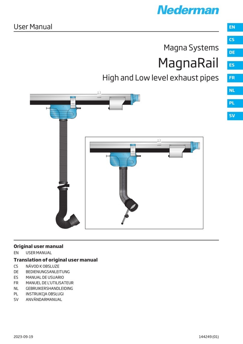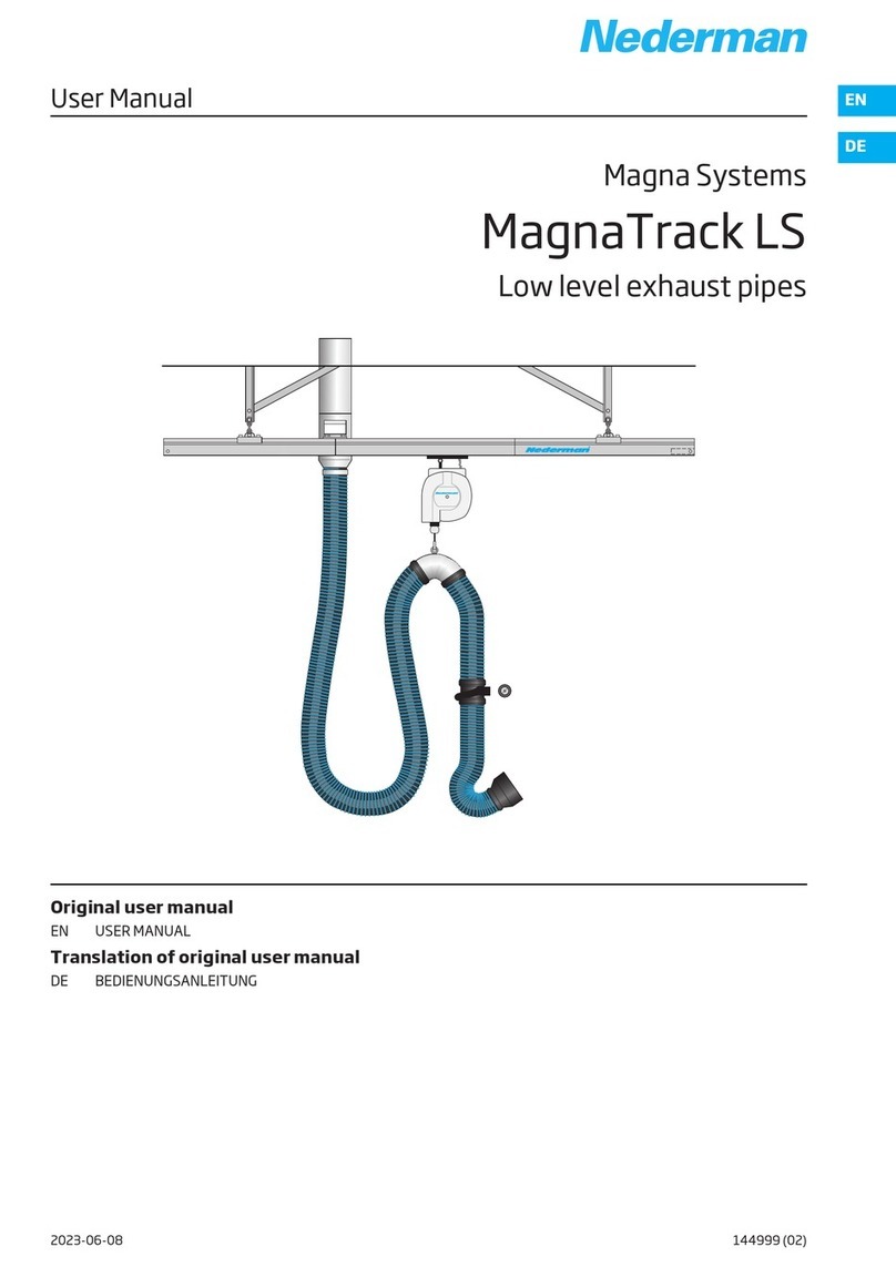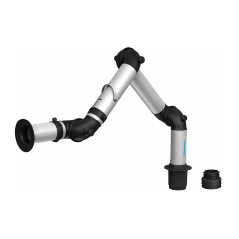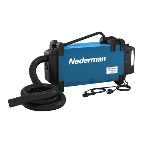
MagnaTrack S
Declaration of Conformit
EN English
Declaration of Conformit
We, AB Ph. Nederman & o., declare under our sole responsibility that
the Nederman product:
MagnaTrack S (Part No. **, and stated versions of **) to which this de-
claration relates, is in conformity with all the relevant provisions of the
following directives and standards:
Directives
2006/42/E , 2014/35/EU, 2014/30/EU
Standards
EN ISO 12100-1-2:2003, EN 61000-6-2, EN 61000-6-4, EN 55011 class
B, EN ISO 20607:2019.
The name and signature at the end of this document is the person re-
sponsible for both the declaration of conformity and the technical file.
CS Český
Prohlášení o Shodě
My, společnost AB Ph. Nederman & o., prohlašujeme na svou zodpo-
vědnost, že výrobek Nederman:
MagnaTrack S (díl č. **, a uvedla, verze **), ke kterému se toto prohlá-
šení vztahuje, je v souladu se všemi příslušnými ustanoveními následu-
jících směrnic a norem:
Směrnice
2006/42/E , 2014/35/EU, 2014/30/EU
Norm
EN ISO 12100-1-2:2003, EN 61000-6-2, EN 61000-6-4, EN 55011 class
B, EN ISO 20607:2019.
Na konci tohoto dokumentu je jméno a podpis osoby zodpovědné za
prohlášení o shodě a soubor technické dokumentace.
DE Deutch
Konformitätserklärung
Wir, AB Ph. Nederman & o., erklären in alleiniger Verantwortung, dass
das Nederman Produkt:
MagnaTrack S (Art.-Nr. **, und bauartgleiche Versionen **), auf wel-
ches sich diese Erklärung bezieht, mit allen einschlägigen Bestimmun-
gen der folgenden Richtlinien und Normen übereinstimmt:
Richtlinien
2006/42/E , 2014/35/EU, 2014/30/EU
Standards
EN ISO 12100-1-2:2003, EN 61000-6-2, EN 61000-6-4, EN 55011 class
B, EN ISO 20607:2019.
Der Name und die Unterschrift am Ende dieses Dokuments sind die für
die Konformitätserklärung und die technischen Unterlagen verant-
wortlichen Personen.
ES Español
Declaración de Conformidad
Nosotros, AB Ph. Nederman & o., declaramos bajo nuestra exclusiva
responsabilidad que el producto de Nederman,
MagnaTrack S (Ref. n.º ** y las versiones indicadas de **), al que hace
referencia esta declaración, cumple con todas las provisiones relevan-
tes de las Directivas y normas que se indican a continuación:
Directivas
2006/42/E , 2014/35/EU, 2014/30/EU
Normas
EN ISO 12100-1-2:2003, EN 61000-6-2, EN 61000-6-4, EN 55011 class
B, EN ISO 20607:2019.
El nombre y firma que figuran al final de este documento corresponden
a la persona responsable, tanto de la declaración como de la ficha técni-
ca.
FR Français
Déclaration de Conformité
Nous, AB Ph. Nederman & o., déclarons sous notre seule responsabili-
té que le produit Nederman :
MagnaTrack S (réf. ** et versions indiquées de **) auquel fait référence
la présente déclaration est en conformité avec toutes les dispositions
applicables des directives et normes suivantes :
Directives
2006/42/E , 2014/35/EU, 2014/30/EU
Normes
EN ISO 12100-1-2:2003, EN 61000-6-2, EN 61000-6-4, EN 55011 class
B, EN ISO 20607:2019.
Le nom et la signature à la fin de ce document sont ceux de la personne
responsable de la déclaration de conformité et du fichier technique.
NL Nederlands
Conformiteitsverklaring
Wij ,AB Ph. Nederman & o., verklaren onder onze verantwoordelijkheid
dat het Nederman product:
MagnaTrack S (artikelnr. **, en vermelde uitvoeringen van **) waarop
deze verklaring betrekking heeft, in overeenstemming is met alle rele-
vante bepalingen van de volgende richtlijnen en normen:
Richtlijnen
2006/42/E , 2014/35/EU, 2014/30/EU
Normen
EN ISO 12100-1-2:2003, EN 61000-6-2, EN 61000-6-4, EN 55011 class
B, EN ISO 20607:2019.
Naam en handtekening onder dit document zijn van degene die verant-
woordelijk is voor zowel de Verklaring van Overeenstemming als het
technische document.
4
