Inax NYSA-1-R-SET(WR)/FW1 User manual

BODY HUG SHOWER
NYSA -1-R-SET(WR)/FW1
NYSA -1-R-SET(WR)/N11
Installation Instructions
■Contents
1. Product Structure ...................................................................... p.2
2. Names and Features of Parts .................................................... p.2
3. Material Packing Slip ................................................................. p.3
4. Required Tools ........................................................................... p.5
5. Confirmation of the mounting position ................................... p.6
6. Mounting method ..................................................................... p.7
7. Inspection after installation ...................................................... P. 17
8. Reference information ...............................................................P. 18

•The arm can be pulled out toward the front about the rotation axis. (Left and right independent)
• You can adjust the spray direction of the movable nozzle.
•The arm tip can be rotated.
1. Product Structure
■The hose that attaches to a faucet is connected to the right side of the product main body.
2.Names and Features of Parts
-2 -
▽floor
1120
movable nozzle
fixed nozzle
Elbow
mirror
Switching
lever
movable nozzle
arm catch
arm
The arm can
be pulled
forward.
1940
tip of
arm 845

Name Main body Mirror frame
Mirror frame upper cover
Shape
Quantity
1 1 1
3.Parts packing slip
Open the package and check if there are any parts or not.
■Body Hug Shower main body: (White) NYSA-1-R/FW1
(Black) NYSA-1-R/N11
-3 -
Name
Truss Head Screw
(M4 x 8)
Low Head Screw (M4 x 8)
Upset Bolt (M5 x 10) silicon tube
Shape
*For fixing mirror frame
upper cover
*For fixing the mirror
frame
*For fixing the
main body *Upset bolt mounting
auxiliary part
Quantity
3 2 2 1
■Back Hanger : NYSA-BH -1 -SET-B
Name Back Hanger Truss Tapping Screw (4 x 25) Curl Plug (Φ6.5 x 35)
Shape
*Back Hanger Fixing
*For Pilot Hole Diameter 6
Φ
Quantity
1 20 25

Name Instruction manual Usage Label
Shape
Quantity
1 1
■Mirror: KGM -2579S
Name Mirror adjusting spacer
Shape
Quantity
1 1
■Connecting Hose Set
<Metal style>
L=600:A-11239-6-PU
Name
connecting hose Connecting Elbows
Shape
Quantity
1 2
-4 -
Usage Label
■Others

4.Required tool
electric screwdriver
Driver Bit (# 2)
Electric Drill Blade (Φ6)
Carbide Drill for Porcelain
Tiles (Φ6・Φ4.5)
Do not use impact drivers.
+ Screwdriver (#2 )
- Driver. sealing gun
water pump
pliers Monkey Wrench Spanner
(For Opposite Side
23, 24 mm)
Cleaning Tools
Neutral Detergent
Wes, etc.
Masking tape
horizontalizer
Plastic
Hammer
Cutter
-5 -
Scale
carpenter's square
(for checking angles) permanent
marker pen
*Precautions for installation work
Wear gloves when installing.
Handle the edges of metal parts with care.
The exterior components of this product are flammable. Be careful of fire, such as cigarette fire.

5.Confirmation of the mounting position
▽washing place floor
230
QJ
Dimens
ions
00
700
〇
QJ
330 (Body Dimensions)105
〇
L
9
L
-6 -
1610
330 (Body dimensions)
1940
890
(Dimensions required for installation)
820 (Body dimensions)
1940
1120
•In order to install the BODY HUG SHOWER, it is necessary to provide a space of 20 mm in the upward
direction (sliding when the main body is mounted) and 50 mm in the downward direction (connecting
hose arrangement,and to prevent interference with faucet handle ).
(See figure enclosed by the circle below.)
For the left and right directions, please check and ensure that there are sufficient reserve dimensions
with the existing items.
•The arm expands by opening to a maximum of 700 mm.
Adjust the installation position so that it does not interfere with Wall,Door,and other existing items.
(To avoid pinching fingers, allow a 30 mm clearance between the arm and adjacent objects ).
50
▽floor
Clearance
Switch Lever
Faucet handle
Required dimension
760mmWx900mmDx1960mmH
845

6.Mounting method
•outline of the installation procedure
⑤Attaching the mirror
frame P. 15
②Attaching the connecting
elbow P. 12
④Assembly of mirror frame
P.14〜15
①Back Hanger Mounting
P.8
⑥Mounting of Connecting Hose
and Shower Hose P. 16
-7 -
③Mounting of
the body
P.13 〜14

Introduction (Back Hanger Mounting Method)
The back hanger of the BODY HUG SHOWER is fixed by driving a tapping screw into the
curl plug. Follow the instructions below to install the product.
■About Tap Drilling
The back hanger is temporarily fixed to a
reference position, and drilling is
performed after marking the drilling
position.
△Caution
Check that there is no water/hot water supply
pipe behind the hole machining area. Drilling can
damage the piping and lead to serious
consequences such as back-of-wall water
leaksage. (See page 10 for tap drilling position . )
■Installation procedure of the plug
①drive a plug
Plastic Hammer
②If it pops out, cut it
with a nipper, etc. ③Fill the plug
with silicon
■About Screw Fixing
Silicon is filled in the tap drill holes and plugs of the back
hanger for fixation.
*When there is a level difference or a warpage in
the mounting part, silicon is applied to the gap
part in a shape of a ball, and the back hanger is
tightened to the extent that it does not deform.
(See page 11)
Tighten by hand
at the end.
-8 -
Depth Approx. 40 mm
Carbide drill for
porcelain tile
Hole
diameter Φ6
If it is difficult to drive,
widen the tap drill hole
slightly to adjust. 【IMPORTANT】Cut to tile surface.

①Temporarily fix the back hanger
Installing the Back Hanger
Tra
s
tappin
Screw
Φ4 mm
x25mm
※1 curl plug
Drive a screw into the oblong hole to make
horizontal leveling.
After the leveling , fix the daruma hole.
*If the back hanger moves to the right and
left when fixing the screw, adjust the
position by lightly tapping the side face of
the back hanger with a plastic hammer
after fixing the screw.
-9 -
Floor~1630
Horizontal
leveling
Φ6 Tap Drill
(On-site processing)
Silicon is not required at this
stage as it is removed by pre-
drilling.
*At the timing of final fixation,
the plug is filled with silicon.
Back Hanger
※3
※ 2
Hook the daruma
hole part to the
screw.

②Perform pre-drilling at fixed positions (12 places)
*Apply silicon to the plug at this timing for the
daruma hole part/oblong hole part.
! Key Points
Be sure to install the specified number of screw,etc.
If the number is insufficient, the strength necessary
for mounting cannot be secured.
Check
■Fix either one of the two or four consecutive
holes surrounded by dashed lines.
■pointed holes are recommended positions.
If Interfering with existing holes, or in close
proximity to joints, use another tap drill hole.
■pointed holes are not used in the
conventional bathroom.
■The screw fixing part is marked with an oil-based
pen.
Point
When drilling is performed in the following
procedure, the hole position are likely to be
exact.
①With the back hanger attached, pre-drilling
is performed on the tile surface by a carbide
drill for tile of the diremeter 4.5.
*The tap drill hole serves as a guide for drilling,
and drilling can be performed at an accurate
position without slipping.
②Remove the back hanger and drill the hole
with the carbide drill for the tile, of the
diameter 6 on the basis of the hole opened
earlier. (Processing Depth: approx. 40mm)
-10-
Φ6 Tap drill
(On-site processing)
curl plug
Using the lower hole of the
back hanger as a guide, drill a
lower hole with a diameter of
4.5 mm.
Remove the back hanger and
enlarge the hole with a diameter
of 6 mm.

③Attach the back hanger
①At a part where a gap is generated between
the back hanger and the wall surface due to
the level difference of the surface of the tile
or the warpage of the mounting surface,
silicon is placed in a ball shape so as to fill the
gap.
②Temporarily hang the back hanger and
press it down while rubbing to crush the silicon
applied in ball shape.
③Tightening of screws near the gap should
be limited to a level that does not deform
the back hanger.
*If it is forcibly tightened, the back hanger is
deformed and the main body cannot be
attached.
-11 -
Tra
s
tappin
Screw
Φ4mm
x25mm
Tighten by hand
at the end.
※1
※1
When there is a level difference or warpage in
the mounting part of the back hanger.
Gaps in
surface steps,
etc.

Attaching the connecting elbow Check
The body and mirror frame are packaged in a
fitted state.
Slide the mirror frame upward and remove it
before mounting the body.
-12 -
mirror frame body
※1
①Peel off the label and stick it on the
underside of the arm.
*To prevent incorrect installation when
connecting the shower hose and connecting
hose.
*Make sure there is no residue of the label.
②Screw it in until it stops.
Connection elbow
*included in hose set
③Return to the position
where the connection elbow
faces the outside of the body.
*Return must be within one
revolution.

mounting of the body
Silicon Tubes
(Included with
Body)
Insert the silicon tube attached to the body into
the screw head, then insert the + screwdriver to
fix it.
(Preventing the screw from falling)
-13 -
Upset bolts
(with washers)
Φ5mm
X10mm
①②
△Caution
When engaging, do not engage by holding the
arm part. Open the arm, put your hands on
both ends of the upper part of the body and
push down.
arm part top of the body
Back hanger
body
Back hanger
body
(Metal frame part)
※ 2
Point
+Screwdriver
Tighten
by hand .
※ 3
To ensure proper disengagement,
check that the fixing holes are
centered in the long holes.

To install
To remove
Assembling the Mirror Frame
mirror frame
Note the top and
bottom
※Indicated on
the reverse side.
mirror mat
Check
To equalize the gap between the mirror and the
frame, temporarily fix one of the provided spacers
at each of the 4 locations on the top,bottom, left
and right places of the mirror frame with masking
tape, and then attach the mirror.
-14 -
①Attach the mirror to the mirror frame
❶
※1
mirror
※1
Remove the relaese paper
from the mirror mat.
mirror
frame
masking tape
spacer
masking
tape
Cross-section of sticking area
spacer
upper
side
Check
When the joint
between the body
and the back hanger
is too tight
Insert a flat-blade screwdriver between
the body and metal fittings near the
"▽" mark and lower the screwdriver to
remove the body.
Insert a flat-blade screwdriver between
the body and the metal fittings near the
"△" mark and lower the screwdriver to
fit together.

②Attach the mirror frame top cover
Attaching the Mirror Frame
mirror
frame
※When the fitting is tight, slide the mirror frame’s
lower part downward while pressing it against the
main body.
-15-
Low head small
screw Φ4mm
X8mm
Truss head
screw
Φ4mm
X8mm
mirror
frame
mirror frame
top cover
Tilting down the arm
makes it easier to
install the mirror frame.
Tighten
by hand .
※1
mirror
frame
body
Vertical section of joint
mirror
frame
※ 2
body
Check
If the mirror frame floats and the lower hole is
misaligned, push the mirror frame toward the
main unit and fix it while aligning the tap drill hole.
Tighten
by hand .
The mirror frame and the top
surface of the main unit must
be aligned.
Approx.
20mm

Mounting of connecting hose
and shower hose
△Caution
•When connecting to other manufacturers'
faucets, the screw diameter may differ. In this
case, use a conversion adapter.
•Do not tighten the bag nut at an angle.
If the bag nut is tightened at an angle, the
threads will be crushed and the nut will not be
able to be tightened.
•Do not damage the packing or allow debris to
sit on it.
* Because the water can't be stopped.
•Do not mistake the connecting position of the
connecting hose.
*If you connect it incorrectly, you will not be
able to switch between hand shower and
body shower.
If a hose with a metal bag nut is used, use a
tool to install it.
-16 -
Check
Tighten
by hand .
Tighten
by hand .
Tighten
by hand .
Tool
tightening
Packing
Packing
Packing
Shower hose
Connecting hose
Connecting
elbow
(PJ 1/2)
Connecting
elbow
(PJ 1/2)
Bag nut
(G 1/2)
Bag nut
(G 1/2)
Bag nut
※metal
(G 1/2)
Packing
Connecting hose
Bag nut
※plastic
(G 1/2)
・The elbow on the right side of the unit is the connection from the faucet.
The elbow on the left side is the connection to the hand shower. If each hose
is installed to the opposite elbow, the switch lever will not work correctly.
・Cannot be combined with shower with water shut-off function.
Internal pressure may be applied to the inside of the unit, resulting in damage.
△Caution

Attaching the Usage Label
Check
•When applying to tile surfaces, avoid joints at
the edges.
*The adhesive strength is weak at the joints,
and the label may easily peel off.
●If there are separate instructions for the label
affixing position in the main part of the
installation manual, follow the instructions.
7.Inspection after installation
④Please clean the bathroom.
-17 -
Shower
hose side
label
If there is interference with fixtures,
etc., move the label to a position that
is easier for the customer to see.
The usage label
Point
Check the water flow with
the arm lowered. (to
prevent water damage).
Check the following items to confirm that the
installation has been completed properly, and
hand it to the customer with the instruction
manual.
And if the usage label isn’t applied, hand it to the
customer.
①Visually check the entire BODY HUG SHOWER
and confirm that there are no abnormalities such
as inclination.
②Gently shake the external parts such as the
arm and the body to check for rattling.
③Check that there is no abnormality by running
water in the order of hand shower and body
shower.
*If the switch is not successful, the connection
between the connecting hose and the shower
hose may be reversed.
Before
applying the
label, ask the
purchaser
whether to
apply a usage
label.

Reference Information
-18 -
•If the hand shower must be installed on the right side, install it as shown below.
PPU-1454 (22100)
•If the distance from the faucet to the main unit is too long for the supplied connecting
hose(L=600mm) to reach, prepare a hose of suitable length with G1/2 connections and
connect it properly.
Standard Right Side
1. Hand shower installation
2. Connection of the main unit to the faucet by connecting hose
Supplied connection hose
(L=600mm)
This manual suits for next models
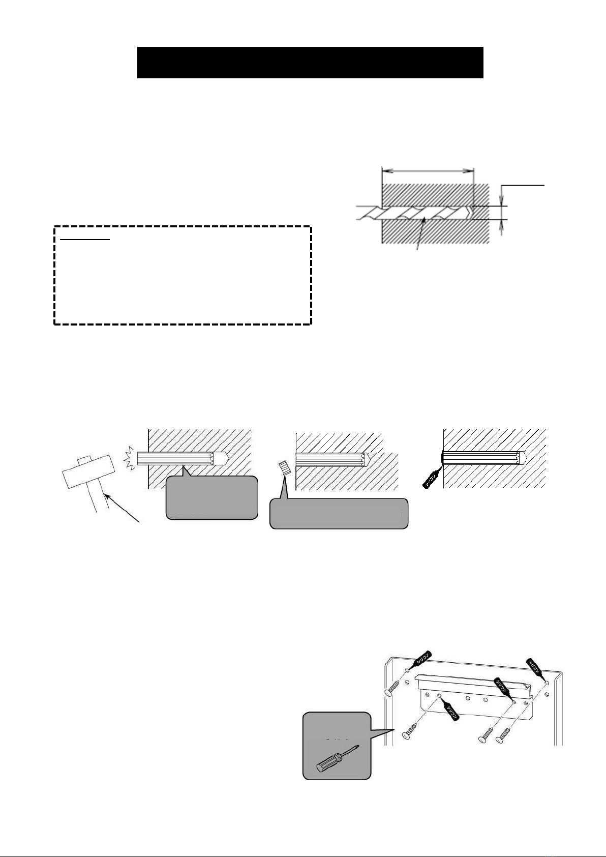
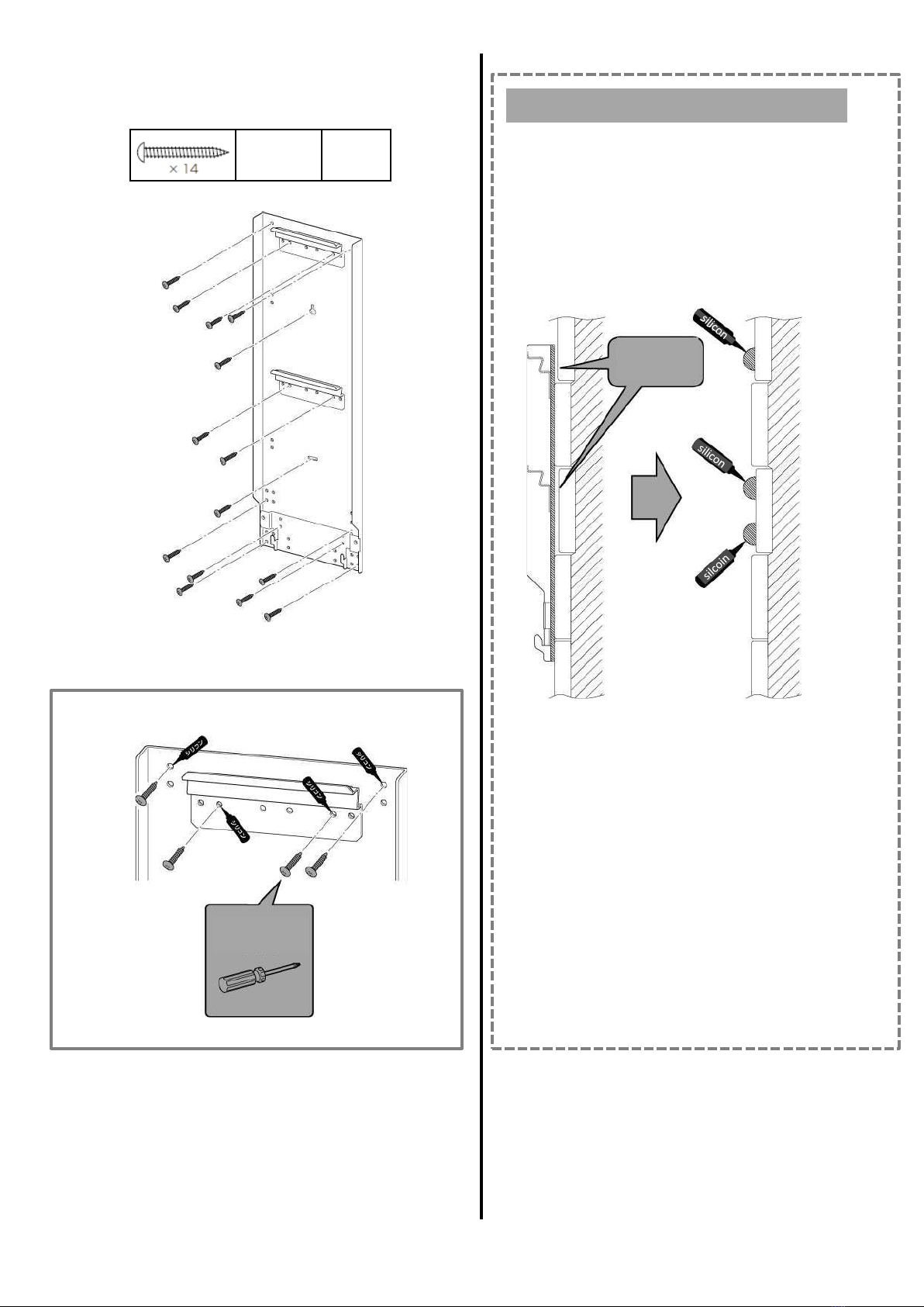
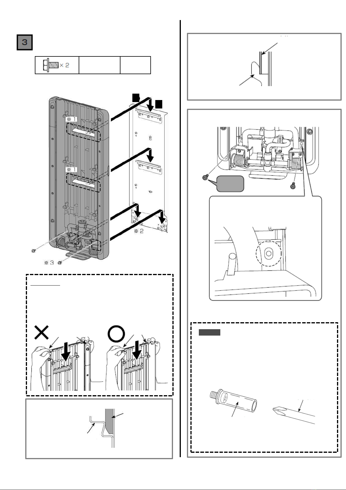
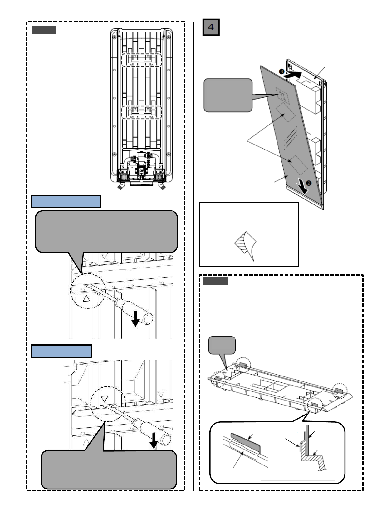
1
Table of contents
Other Inax Bathroom Fixture manuals
Popular Bathroom Fixture manuals by other brands

Bossini
Bossini WC69051 Instructions for use

Hans Grohe
Hans Grohe Croma Showerpipe 220 Instructions for use/assembly instructions

Spectrum Brands
Spectrum Brands Pfister McAllen R89-XMCA Maintenance & Care Guide

iDo
iDo PORSGRUND Showerama Operating and maintenance instructions

Hans Grohe
Hans Grohe Rainfinity 130 3jet 26865 7 Series Instructions for use/assembly instructions

Symmons
Symmons Degas 543TB-18 Operation & maintenance manual