InclusiveEnergy Smart Biogas User manual

Smart Biogas
Installation manual & data sheet
InclusiveEnergy


3
CONTENTS
General Information
Safety instructions
Warranty
Online support
Product Overview
Smart Meter
Location
Sim Card
Recommended installationlocation
Venturi & Meter Installation
Wrong Installation Orientation Examples
Set Up
Battery connection
Connecting to network
Know your lights
Connecting antenna
PV Panel Installation
AC/DC Power adapter
Software Registration
SB Home
Product Datasheet
4
5
6 - 7
8 - 10
11
12 - 13
14 - 15
16 - 17
18 - 19

4
This product is subject to a one (1)
year manufacturing warranty.
This covers any defects or material
issues under normal use and
conditions for the above stated
period from the original invoice date.
The manufacturer agrees to repair
or replace any defected components
of the product within the period.
THIS WARRANTY IS VOID IF THE
DEVICE IS OPENED WITHOUT THE
PERMISSION OF A QUALIFIED
BIOGAS TECHNICIAN, ENGINEER
OR PLUMBER.
General Information
Safety instructions
Warranty
Online support
Smart Biogas meter should be
installed by a qualied gas plumber.
Only a trained and suitably qualied
biogas technician, engineer or
plumber should make changes
to biogas pipework. All pipe work
should be tested for leaks at a
suitable pressure on completion of
installation of the meter.
https://support.inclusive.energy/
portal/en/kb
5
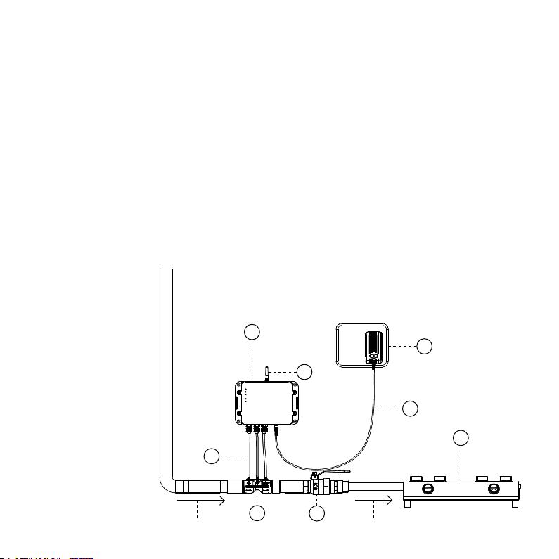
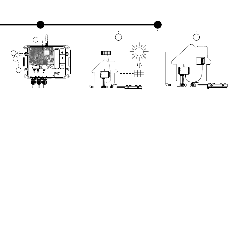
Product Overview
Part list
1. Smart meter (P1, P2 or P3)
2. Venturi
3. Gas valve
4. Tubes
5. Wire connected to PV panel
or AC/DC adapter
6. Gas appliance
7. PV panel or AC/DC adapter
8. Antenna
8
4
7
5
1
23
6
Gas ow from digester Gas ow to appliance
Smart Meter Models
P1 - Static pressure sensor only
P2 - Flow sensor only
P3 - Both ow and static pressure
sensors

6
Smart Meter Preparation
Location
SIM Card
Location of the smart meter needs
to be weather protected, so it needs
to be inside or under a canopy.
Smart meter is rated as IP65 when
installed as per the installation
manual which gives protection
against low pressure water jets,
as well as condensation and water
spray.
In most cases a SIM card will come
supplied and already tted into the
meter but if it is not or you need to
install a different SIM or replace the
SIM for any reason, you will need:
• Nano SIM
• 2G enabled SIM
• Minimum of 8MB per month data
pack
• Recurring data pack
Most networks will not need a
change to the APN settings but
if you are using a specialised
M2M SIM card, the APN settings
may need to be changed at the
manufacturer.
It is advised to be sure that 2G
network is available in the area
where you are installing.
To insert the SIM, remove the device
enclosure and insert according to
the image.
7
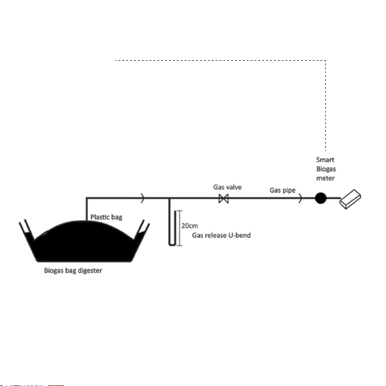
Recommended Installation Location
Smart meter installed before the
gas appliance
If you would like to install the smart
meter in a different location please
talk to a member of the Inclusive
Energy team.
Gas appliance

8
Max 25cm
Venturi & Meter Installation
Check the venturi before
installation
• Remove the venturi caps and
check internal bores are smooth
and that there are no blockages in
the bore or the teets off the top of
the venturi. Teets can usually be
unblocked with a paperclip if there
is a small blockage. More stubborn
blockages in the teet can be drilled
out but is important to ensure that
all teets have the same internal
diameter.
Prepare the pipework for
installation
• Prepare the threaded ends with
gas thread tape as appropriate.
• The thread on the venturi is a
taper thread and is designed to seal
against parallel female ttings.
• The pipe may need adaptors to
screw the ends of the venturi into
the pipe. These will need to be
bought locally.
• The installation should be
undertaken by a qualied gas
plumber, as is the case for any pipe
tting.
• Glues are not required.
Install the venturi in horizontal
pipework
• Ideally the venturi should be
approximately level/horizontal but
allow water to drain in the pipe work
towards a water trap or an exit point.
• Step 3A shows the ideal position
of the venturi in horizontal pipework
but if necessary the venturi can
be installed in vertical pipework as
step 3B.
• The venturi will need to ‘point’ (see
arrow on the venturi) in the direction
of the gas ow.
• The teets should always
point roughly upwards to allow
condesation to drain back into the
pipe.
2 31
Venturi to be placed parallel to the ground
A

9
Connect tubes in the correct order
• The tubes need to be connected
from the smart meter to the venturi
with the tubes connecting the ports
of the meter to the corresponding
port of the venturi (A to A, B to B,
etc.).
• Ensure that the tube lengths are
cut to size to avoid excessive bends
or sags whilst also not stressing
the teets.
(If you are using a version of the
meter which only has either a ow
or pressure sensor, then ensure
that the venturi teets that are
not connected to the pipes are
tightly closed with the caps that
came with it.)
If gas ows from left to right If gas ows from right to left
Connect tubes in the correct order
• Note that in this case the teet A on
the venturi will not be underneath
port A of the meter as the venturi
orientation is ipped. The tubes still
need to connect the meter ports
to the corresponding venturi ports
(A to A, B to B etc.) so in this case
the tubes will criss-cross as per the
diagram above.
Install the venturi in vertical
pipework
• (Refer to step 3A for general
principles) If the gas pipe is installed
in the vertical orientation, you can
install the venturi vertically as
shown.
Position smart meter appropriately
above the venturi
• Position the smart meter above
the venturi (never below). Maximum
25cm above.
• Ensure that the tubes connected
between the venturi and the smart
meter are positioned so that any
condensation will return to the pipe.
4
AB
Gas ow
from
digester
Gas ow to
appliance
Connection to
PV panel
A B C
Gas ow to
appliance
Gas ow
from digester
Connection to
PV panel
C B A
B
Max 25cm

10
The tubes connect the meter
ports to the corresponding venturi
ports.
Any unused teets are capped with
the rubber cap provided (P1 and P2
models only).
The whole installation has been
checked for leaks under pressure
(main gas valve open) using soapy
water.
Quality assurance
The Smart Meter is installed
above the venturi.
The Smart Meter is weather
protected.
The venturi does not impede ow
of condensation back to the water
drain.
The venturi teets are pointing
upwards.
The venturi ow arrow points in
the direction of gas ow.
The tubes allow free ow of
condensation away from the meter
and back into the gas pipe.
Max 25cm
5
11
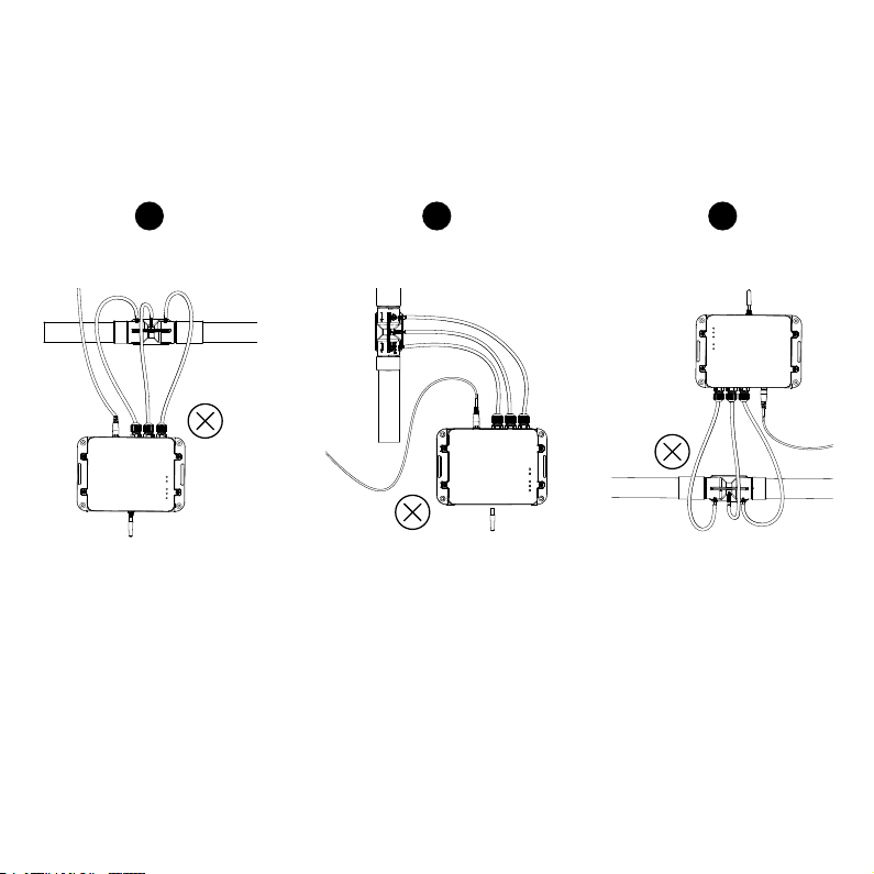
• The smart meter must be installed
above the venturi.
• The smart meter must be installed
with the antenna pointing upwards.
• The tubes must not have any sags.
1 2 3
Wrong Installation Orientation Examples
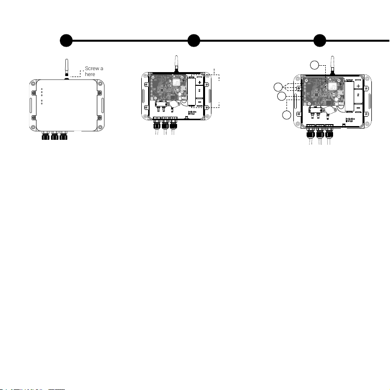
12
Set Up
2 31
+ve at the top
and -ve at the
bottom
Insert battery
• Once the meter and venturi is
installed, open the top cover of the
smart meter to connect the battery.
• Before connecting battery, observe
the polarity marked on the cell and
ensure that it is inserted in the
right way around as marked at the
bottom of the battery holder.
• The battery will be connected once
you plug the connector coming out
of battery into the white socket on
the bottom right corner of the board.
• Note - The battery should always
be installed before the solar panel is
plugged in.
• Once the battery is plugged in, the
device will power up and all LEDs
will light up for a second and you
will then see that only the power
LED and the battery level LEDs will
be ON.
Ensure correct polarity here
Incorrect polarity
will result in
product breakage
Connect to network
• If the SIM is inserted and the
battery is connected, you will
observe the following pattern on the
tiny red LED (1) when the device is
powered up for the rst time or if
restarted during a service.
1. Flashes every 1 second - It
indicates that the device is
searching for a network.
2. Flashes rapidly - After about 2
minutes or so, the red LED will start
ashing rapidly and followed by the
green data LED (3) which indicates
that the device has established
connection to a network and is
sending data.
3. Flashes every 3 seconds - After
the above step, the red LED (1)
will ash every 3 seconds and the
data LED (3) will always stay ON
which indicates that the device is
registered to the network and is able
to connect to the server. LED (3) will
ash rapidly everytime data is sent.
2
1
3
4
Connect antenna
• The antenna needs to be screwed
on to the smart meter as shown
here.
• NOTE: Installation in a metal box
e.g. a corrugated metal house, will
signicantly reduce signal strength.
Screw antenna
here
13
Install PV panel
• The PV panel should be installed
in a location with good access to
sunlight and in an unshaded spot.
• The PV should be installed at an
angle to allow water run off and be
accessible for regular cleaning.
• In some circumstances the PV
cable may need to be extended to
reach an optimum location.
Connect adapter
• If you connect the AC/DC adapter
instead of the PV Panel, then it
should be connected as shown
above.
• The AC/DC adapter provided is of
9V, 1A and comes with an European
type-C, 2-pin plug.
Note - Depending upon the type of
socket available at the installation
site, you may have to use an extra
conversion plug with an European
2-pin plug socket.
4 5
AB
If using
solar panel
If using
mains power
Check the LEDs
• Yellow LEDs (2) indicate the
battery level. When one of the LEDs
ash, it means that the battery is
charging. If it is not ashing during
the day time, check the PV panel
connection and/or if there is shade
or dust on the panel.
• The top green LED (3) represents
data activity. It will ash when
sending data or performing an Over
The Air update (OTA). It will stay
on after successfully sending data.
It will turn off if the device fails to
connect with the data network or
server.
• The bottom green LED (4) is to
indicate that the device is on and
has power.
2
1
3
4

14
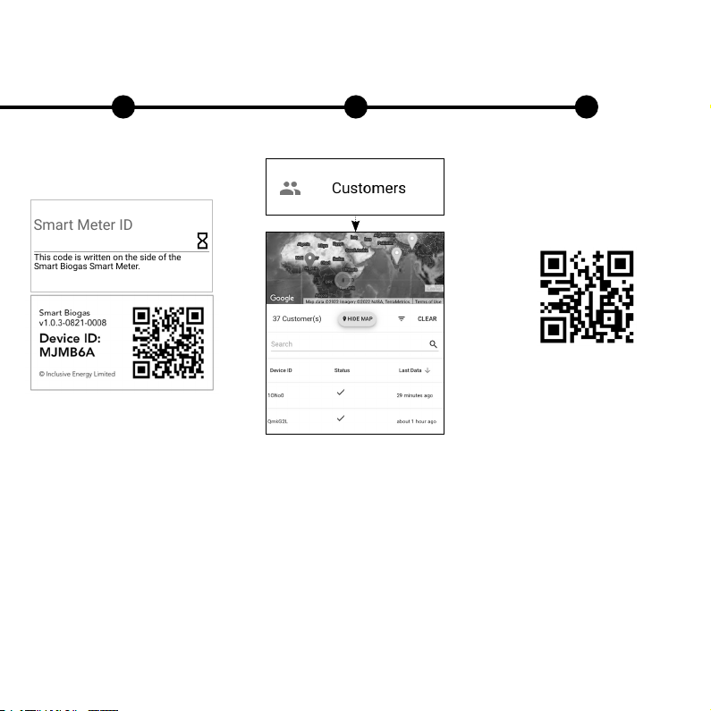
Software Registration
2 31
Go to http://www.smartbiogas.io or
scan the QR code.
Login and click to Register a New
Customer.
If you don’t have a Smart Biogas
login, please contact your supplier
or Inclusive Energy.
Fill in all the details required and
click next to progress through the
forms.
15
4 5 6
IMPORTANT: Take a note of the
meter ID that is written on the side
of the Smart Biogas meter. This
needs to be entered during the
registration process.
Once you have completed the form
you can check out the Customers
page on the website and the meter
that you have registered should now
be present on the list.
For more details about the software
you can view the Smart Biogas
platform walkthrough video by
scanning the QR code.
This code is written on the side of the
Smart Biogas Smart Meter.
Smart Meter ID

16
SB Home
SB Home is an Android and iOS
application. It is designed for people
who have Smart Biogas meters
installed with their biogas digesters.
It not only gives access to their data
but also tracks their payments and
gives access to direct support and
help.
(NOTE: The application won’t work
until the device has been registered
to a customer on the main SB
platform)
To download, follow link - http://
onelink.to/sbhome or scan the
above QR code.
To get started, the customer will
need to enter the device ID that is
written on the side of their smart
biogas meter and click initialize.
21

17
An email or SMS will be sent to the
contact details that are connected
to your customer. It will contain their
log in details and a link to set their
password.
Once they have their new login
credentials, they can now log into
the app.
After logging in, the customer can
view their digester ll level, gas
consumption, payment history if
available and have access to direct
support.
3 4 5

18
Product Datasheet
Inside the box Specications Data and Network
• Smart Biogas Meter
• Flow sensor and/or pressure
sensor
• Venturi pipe tting (3/4” or 1”) -
HDPE
• Measurement tubes
• 3.7 V 18650 Lithium ion battery
(1x battery or optionally 2x batteries)
• 3 W 6 V solar panel with 3m cable
or AC/DC adapter
• Global SIM card (optional)
• Caps for venturi
• Antenna
• Flow and pressure as per table
• Voltage range 5 - 15 volt DC input
• Operating temperature 0ºC to 60ºC
• 3 days battery life without
sunshine or electricity
• Weather resistant enclosure
• 170 x 117 x 44mm enclosure size
• Enclosure has various mounting
options for situational exibility
Data collected every minute and
sent at set intervals (e.g. hourly) :
• Average pressure for the previous
1 minute (if pressure sensor is
tted).
Data collected every 1 hour
(congurable)
• Gas consumption total since the
beginning of the device’s existence
(if ow rate sensor is tted).
Model Number Venturi Size and Bore Flow Rate Max Static Pressure
P1 3/4”, bore=8mm NA 10kPa
1” , bore=16mm NA 10kPa
P2 3/4”, bore=8mm 2m3/hr NA
1” , bore=16mm 20m3/hr NA
P3 3/4”, bore=8mm 2m3/hr 10kPa
1” , bore=16mm 20m3/hr 10kPa

19
System overview
System Overview
System Overview
1" 1"
Gas Appliance

Table of contents
Popular Measuring Instrument manuals by other brands


Verizon
Verizon LT70B user guide

Beijing Dianotech Sci-Tech
Beijing Dianotech Sci-Tech FIC-Q100N Instructions for operation

BRONKHORST
BRONKHORST MASS-STREAM D-6400 instruction manual

Turtle Tough
Turtle Tough PEEK installation manual

sebaKMT
sebaKMT Correlux C-3 user manual

AXE
AXE MCH Series Operation manual


